manuals.online logo
Brands
  1. Home
  2. •
  3. Brands
  4. •
  5. Wyrestorm
  6. •
  7. Extender
  8. •
  9. Wyrestorm EX-100-4K-PRO User manual

Wyrestorm EX-100-4K-PRO User manual

4K HDMI over HDBaseT™ 2.0 Extender Set
with Ethernet | USB 2.0 | S/PDIF | IR & RS-232 (100m/328ft)
EX-100-4K-PRO Quickstart Guide
In the Box
1x EX-100-4K-PRO Transmitter
1x EX-100-4K-PRO Receiver
1x 12V DC 2A Power Supply (US/UK/EU)
2x 2-pin Screw Down Phoenix Connectors
2x 3-pin Screw Down Phoenix Connectors
2x IR Emitters
2x Wide-band IR Receivers (30-50KHz)
4x Mounting Brackets (1pr for TX and 1pr for RX)
1x Quickstart Guide (this document)
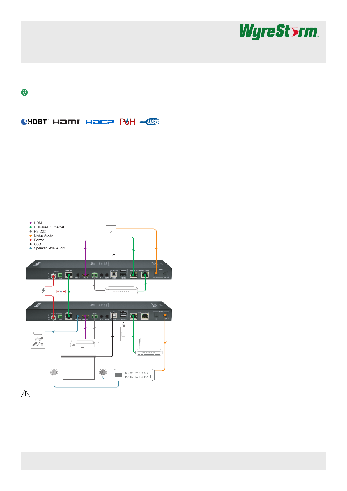
Basic Wiring Diagram
HDMI
Digital Audio
HDBaseT
Cat5e/6/6a
Ethernet
Cat5e/6/6a
Ethernet
Cat5e/6/6a
EX-100-4K-PRO Transmitter (TX)
EX-100-4K-PRO Receiver (RX)
Ethernet
Cat5e/6/6a
Personal Computer
Amplifier
Isochronous
USB 2.0 Data
USB 2.0
Host
USB
Flash Drive
Short Throw
Projector
Hearing
Induction Loop
Router or Switch
or
12 DC 2A
Power Supply
HDMI
Analog Audio
RS-232
Interactive Whiteboard
RS-232 from Control System
KEY
IMPORTANT!
Do not connect or disconnect (hot plug) the HDMI, or HDBaseT
connections while the transmitter or receiver is powered on. Doing
so may cause damage to the units or connected devices.
Additional Information
This Quickstart Guide provides the basic steps for the common uses of
this product. Refer to the Installation Guide and other documentation on
the product page for additional information.
Before Beginning
WyreStorm recommends visiting the product page before installing this
product for updates to this Quickstart Guide as well as other information
about this product.
Verify that all items are included in the packaging per the In The Box list.
Pre Wire
1. Run a Cat5e/6/6a cable from the transmitter location to the receiver
location. Terminate the cable per the HDBaseT Wiring section.
2. (Optional) If using IR emitters or 3rd party connecting blocks at
either the transmitter or receiver, run the wire and terminate per the
IR TX (Emitter) Wiring section.
3. (Optional) If using IR receivers or an IR control system at either the
transmitter or receiver, run the wire and terminate per the IR RX
(Receiver) Wiring section.
4. (Optional) If using RS-232 pass-through, run the wire and terminate
per the RS-232 Wiring section.
Transmitter Installation
1. Connect an HDMI source to the HDMI In on the transmitter using
an HDMI cable from a high quality brand such as WyreStorm
Express.
2. Using the cable created in Pre Wire step 1, connect the 8-pin RJ-45
female plug to the HDBT Out jack on the transmitter.
3. (Optional) Place an IR emitter onto the source device near the
device’s IR sensor and connect the opposite end to an IR TX port.
4. (Optional) Connect an IR Receiver to the transmitters IR RX
port. If using a control system, connect it to an IR RX port on the
transmitter using the WyreStorm CAB-IR-LINK or the cable created
in Pre Wire step 3.
5. (Optional) Using the cable created in Pre Wire step 4, connect the
3-pin connector to the RS-232 port on the transmitter and the
opposite end to a port on a control system.
6. (Optional) If using audio sent from the remote display via HDBaseT,
connect the S/PDIF Out to a TOSLInk digital input on an AV
Receiver or amplier.
7. If using PoH from the transmitter to power the receiver, connect the
included 12V DC 2A power supply to the DC 12V jack.
Receiver Installation
1. Connect the HDMI Out on the receiver to an input on the display
using an HDMI cable from a high quality brand such as WyreStorm
Express.
2. Using the cable created in Pre Wire step 1, connect the 8-pin RJ-45
female plug to the HDBT In jack on the receiver.
3. (Optional) Place an IR emitter onto the display device near the
device’s IR sensor and connect the opposite end to an IR TX port.
4. (Optional) Connect an IR Receiver to the receivers IR RX port. If
using a control system, connect it to an IR RX port on the receiver
using the WyreStorm CAB-IR-LINK or the cable created in Pre Wire
step 3.
5. (Optional) Using the cable created in Pre Wire step 4, connect the
3-pin connector to the RS-232 port on the receiver and the opposite
end to the port on the display device.
6. If using PoH from the receiver to power the transmitter, connect the
included 12V DC 2A power supply to the DC 12V jack.
Copyright © 2015 WyreStorm Technologies | wyrestorm.com
EX-100-4K-PRO Quickstart Guide | 160412
North America: 518-289-1294 | EMEA/ROW: 44 (0) 1793 230 343
[email protected]
1 of 4
WyreStorm recommends reading through this document in
its entirety to become familiar with the product’s features prior to
starting the installation process.
Fully featured HDMI extender set using HDBaseT 2.0 specication allowing 4K video, HD audio, Ethernet, USB, Power and control over 100m/328ft of
Cat6 cable.
Copyright © 2015 WyreStorm Technologies | wyrestorm.com
EX-100-4K-PRO Quickstart Guide | 160412
North America: 518-289-1294 | EMEA/ROW: 44 (0) 1793 230 343
[email protected]
2 of 4
Front Panel (TX/RX)
Rear Panel (TX/RX)
Set
3 Position Dipswitch:
Used to enables/disable long cable mode, congure RS-232 port, and congure USB mode.
See Dipswitch Settings.
Power LED Solid: The transmitter is powered On
Off: The transmitter is powered Off
Status LED Flashing: The transmitter is operating normally
Off: The transmitter is Not operating normally
HDCP LED
Solid: Audio and Video signal is HDCP protected.
Flashing: Audio and Video signal is not HDCP protected.
Off: No Audio and Video signal.
LINK LED Solid: Link to receiver has been established.
Flashing: Link to receiver has not been established.
Power In
5.5mm Male Barrel Jack | 2-pin Screw Down Phoenix Connector
Connect to the included 12V DC 2A power supply. Only connect to either the transmitter or receiver when using PoH.
See Power Supply Wiring.
HDBT Out (TX)
HDBT In (RX)
8-pin RJ-45 female
Connect the transmitter HDBT Out to receiver HDBT In using the cable created in Pre Wire step 1.
Line In (TX)
Line Out (RX)
3.5mm (1/8in) Stereo Jack
In: Connect to the analog audio output of a device to send audio to the remote display location via HDBaseT.
Out: Connect to an analog audio input of a device to receive audio from the remote display location via HDBaseT.
HDMI In (TX)
HDMI Out (RX)
19-pin type A HDMI female digital video/audio: Supports HDMI and DVI/D (requires adapter-not included). Limited to
297MHz pixel clock
RS-232
3-pin Screw Down Phoenix Connector
Used to send and receive RS-232 signals to/from the source and remote locations via HDBaseT and rmware
updates.
See RS-232 Wiring.
IR TX/RX
3.5mm (1/8in) Mono Plug
IR TX: Connect to the supplied IR emitter to control a local device from the remote display location via HDBaseT.
IR RX: Connect to the supplied IR receiver to send IR to the remote display location via HDBaseT.
See IR Wiring.
USB Host: Connect to a PC or other device to control via USB peripherals
Device: Connect USB peripherals to control a device connected to USB Host
LAN 8-pin RJ-45 female | 10/100 Mbps auto-negotiating
Connect to a Local Area Network or network device for Ethernet pass-through via HDBaseT.
S/PDIF In/Out
TOSLink (Digital Optical)
In: Connect to the S/PDIF digital audio output of a device to send audio to the remote display location via HDBaseT.
Out: Connect to the S/PDIF digital audio input of a device to receive audio the remote display location via HDBaseT.
EX-100-4K-PRO TX
EX-100-4K-PRO RX
EX-100-4K-PRO TX
EX-100-4K-PRO RX
Copyright © 2015 WyreStorm Technologies | wyrestorm.com
EX-100-4K-PRO Quickstart Guide | 160412
North America: 518-289-1294 | EMEA/ROW: 44 (0) 1793 230 343
[email protected]
3 of 4
HDBaseT Wiring
IMPORTANT! Wiring Guidelines
• The use of patch panels, wall plates, cable extenders, kinks in cables,
and electrical or environmental interference can have an adverse
effect on HDBaseT transmission limiting performance. Steps should
be taken to minimize these factors (or remove completely) during
installation for best results.
IMPORTANT!
If a patch panel is being used, Cat6a or higher cable must be used to and
from the transmitter and receiver as well as inside the panel to avoid loss
of signal.
• While similar in nature, the HDBaseT protocol is different than Ethernet
and voltages provided for PoH can be higher than those provided by
PoE. For this reason, never connect an HDBaseT link to an Ethernet
router or switch to avoid damaging the connected devices.
Wiring for HDBaseT follows the EIA T568B standard.
Pin 1
Pin 8
Wire colors shown follow EIA/TIA-568B standard.
Pin 1:
Pin 2:
Pin 3:
Pin 4:
Pin 5:
Pin 6:
Pin 7:
Pin 8:
White/Orange
Orange
White/Green
Blue
White/Blue
Green
White/Brown
Brown
Supported Video Resolutions
The type of category cable used and the distance between the
transmitter and receiver can restrict the available video resolution.
Cable Type Range Supported Resolution
Cat5/5e/6
150m/492ft Up to 1080p@60Hz 24bit
100m/328ft Up to 1080p@60Hz 36bit
90m/295ft 1080p@60Hz 48bit
Cat6a
150m/492ft 1080p@60Hz 3D
100m/328ft 4096x2160p@60Hz 4:2:0
4K@30Hz 4:4:4 | 4K@60Hz 4:2:0
Note:
• Transmitter and receiver must have long cable mode enabled to reach
150m/492ft. See Dipswitch Settings.
• When connected to a class B HDBaseT receiver, the supported
distance is limited to 70m/230ft 1080p.
Power Supply Wiring
The EX-100-4K-PRO can supply power via PoH to the receiver or
transmitter. The included power supply must be used on either the
transmitter or receiver in order for PoH to power the opposite device.
The power supply can connect using either the attached barrel connector
the included 2-pin Screw Down Phoenix Connector.
Wire colors shown are for pin identificaiton only and do not
represent any wiring standard.
Pin 1:
Pin 2:
PWR - (GND)
PWR + (Positive)
1 2
IR Wiring
IR TX (Emitter) Wiring
Connection for IR TX (transmit) uses a 3.5mm (1/8in) mono plug.
Tip: IR Signal
Sleeve: Ground (GND)
IR RX (Receiver) Wiring
Connection for IR RX (receive) uses a 3.5mm (1/8in) stereo jack that
outputs +5V DC to power the included IR receiver.
IMPORTANT! IR TX Connection Guidelines
3rd party IR receivers may require a different voltage, refer to the
documentation provided with the IR receiver before making any
connections to avoid damaging the device.
When connecting to an IR control system use the WyreStorm CAB-IR-
LINK stereo to mono cable to remove the sleeve +5V DC.
Tip:
Ring: IR Signal
+5V DC
Sleeve: Ground (GND)
RS-232 Wiring
RS-232 Connection Guidelines
The following wiring diagram shows the pinouts for the extender set.
While not shown, connect the TX (transmit) to RX (receive) pins at the
control system or PC side of the cable.
Most control systems and computers are DTE where pin 2 is RX,
this can vary from device to device. Refer to the documentation for
the connected device for pin functionally to ensure that the correct
connections can be made.
Wire colors shown follow EIA-561 standard.
Pin 1:
Pin 2:
TX (Transmit)
RX (Receive)
Pin 3: Ground (GND)
1 2 3
Line In/Out Wiring
Connection for Line In/Out uses a 3.5mm (1/8in) stereo jack.
Tip:
Ring:
Left Channel
Right Channel
Sleeve: Ground (GND)
Copyright © 2015 WyreStorm Technologies | wyrestorm.com
EX-100-4K-PRO Quickstart Guide | 160412
North America: 518-289-1294 | EMEA/ROW: 44 (0) 1793 230 343
[email protected]
Warranty Information
This product is covered by a 3 year limited parts and labor warranty. During this period there will be no charge for unit
repair, component replacement or complete product replacement in the event of malfunction. The decision to repair
or replace will be made by the manufacturer. This limited warranty only covers defects in materials or workmanship
and excludes normal wear and tear or cosmetic damage.
Visit the product page located at wyrestorm.com for additional information on this product including important
technical information not provided in this document and warranty terms & conditions.
4 of 4
Dipswitch Settings
The dipswitches on the front panel congure various functions within the
EX-100-4K-PRO.
Note:
• Switches that are greyed out can be in any position for the desired
function.
RS-232
Passthrough RS-232 Firmware
Update
USB Host 1080p 5.1ch
Long Cable
Mode Disabled 1080p 7.2ch
ON
123
ON
123
ON
123
ON
123
ON
123
ON
123
Specications
Audio and Video
Audio Formats 2ch analog and Up to 7.1 DTS-HD
Master Audio and Dolby True HD
Video Resolution 4096 x 2160p @ 60Hz 4:2:0
1920 x 1080 @ 60Hz (1080p60)
Color Depth 1080p: 48bit | 4K: 24bit
Maximum Pixel Clock 297 MHz
Communication and Control
HDBaseT HDCP | EDID | PoH | USB 2.0 |
Bi-directional IR and RS-232
HDMI HDCP | EDID | CEC
DVI/D supported with adapter (not
included)
Ethernet 10/100 Mbps auto-negotiating
IR Bi-directional over HDBaseT
RS-232 Bi-directional over HDBaseT
USB Local Host Control | Remote Host over
HDBaseT
Power
PoH 48V 15.4W
Power Supply Input: 100~240V AC 50/60Hz
Output: 12V DC 2A
Max Power Consumption 26.5W
Environmental
Operating Temperature 32°F ~ 113°F (0°C ~ 45°C)
10% ~ 90%, non-condensing
Storage Temperature -4°F ~ 140°F (-20°C ~ 70°C)
10% ~ 90%, non-condensing
Dimensions and Weight
Height 20mm/0.79in
Width 272mm/10.7in
Depth 99mm/3.89in
Weight 0.72kg/1.58lbs
Regulatory
Safety and Emission CE | FCC
RoHS Compliant
Troubleshooting
No or Poor Quality Picture (snow or noisy image)
• Verify that power is connected to the transmitter and receiving device.
If using a display with a built in receiver, verify that the device is
powered on.
Note: When using PoH, to power the transmitter, verify that the
HDBaseT cable is properly terminated per the HDBaseT Wiring section.
• Verify that the transmitter, receiving device, and display support the
output resolution of the source. See Supported Video Resolutions.
• Verify that the HDBaseT cable is properly terminated per the HDBaseT
Wiring section.
• Verify that all source and HDBaseT connections are not loose and are
functioning properly.
No or Intermittent 3rd party Device Control
• Verify that the IR cable(s) is properly terminated.
See IR Wiring
• Verify that the IR emitter is located near the IR receiver on the device.
Troubleshooting Tips:
• WyreStorm recommends using a cable tester or connecting the cable
to other devices to verify functionality.
• Use a flashlight to locate the IR receiver behind any tinted panels on
the device being control.

Other Wyrestorm Extender manuals

Wyrestorm eX-70-4K User manual

Wyrestorm

Wyrestorm eX-70-4K User manual

Wyrestorm EX-100-4K-PRO User manual

Wyrestorm

Wyrestorm EX-100-4K-PRO User manual

Wyrestorm EX-1UTP-IR-100-EDID User manual

Wyrestorm

Wyrestorm EX-1UTP-IR-100-EDID User manual

Wyrestorm EX-40-G2 User manual

Wyrestorm

Wyrestorm EX-40-G2 User manual

Wyrestorm EX-SW-0301-H2 User manual

Wyrestorm

Wyrestorm EX-SW-0301-H2 User manual

Wyrestorm EX-100-H2-EARC User manual

Wyrestorm

Wyrestorm EX-100-H2-EARC User manual

Wyrestorm EX-35-4K User manual

Wyrestorm

Wyrestorm EX-35-4K User manual

Wyrestorm EX-SW-0301-H2 User manual

Wyrestorm

Wyrestorm EX-SW-0301-H2 User manual

Wyrestorm EX-1UTP-IR-70 Manual

Wyrestorm

Wyrestorm EX-1UTP-IR-70 Manual

Wyrestorm EX-70-H2 v2 User manual

Wyrestorm

Wyrestorm EX-70-H2 v2 User manual

Wyrestorm EX-80-KVM User manual

Wyrestorm

Wyrestorm EX-80-KVM User manual

Wyrestorm EX-40-G3 User manual

Wyrestorm

Wyrestorm EX-40-G3 User manual

Wyrestorm EX-SW-0401-H2-PRO User manual

Wyrestorm

Wyrestorm EX-SW-0401-H2-PRO User manual

Wyrestorm EX-70-G2 Series User manual

Wyrestorm

Wyrestorm EX-70-G2 Series User manual

Wyrestorm EX-70-H2X User manual

Wyrestorm

Wyrestorm EX-70-H2X User manual

Wyrestorm EX-35-H2 User manual

Wyrestorm

Wyrestorm EX-35-H2 User manual

Wyrestorm EX0101-WH1 User manual

Wyrestorm

Wyrestorm EX0101-WH1 User manual

Wyrestorm eX-70-4K User manual

Wyrestorm

Wyrestorm eX-70-4K User manual

Wyrestorm EX-100-H2 User manual

Wyrestorm

Wyrestorm EX-100-H2 User manual

Wyrestorm EXP-EX-COAX-50 User manual

Wyrestorm

Wyrestorm EXP-EX-COAX-50 User manual

Wyrestorm EX-1UTP-IR-50-POH User manual

Wyrestorm

Wyrestorm EX-1UTP-IR-50-POH User manual

Wyrestorm EXP-EX-35-G2 User manual

Wyrestorm

Wyrestorm EXP-EX-35-G2 User manual

Wyrestorm EX-70-H2 User manual

Wyrestorm

Wyrestorm EX-70-H2 User manual

Wyrestorm EX-1UTP-IR-50 User manual

Wyrestorm

Wyrestorm EX-1UTP-IR-50 User manual

Popular Extender manuals by other brands

J-Tech Digital JTECH-VW-4KPR Operation instructions

J-Tech Digital

J-Tech Digital JTECH-VW-4KPR Operation instructions

Satel ACX-201 manual

Satel

Satel ACX-201 manual

gofanco HDwireless1x4 user guide

gofanco

gofanco HDwireless1x4 user guide

HiBoost Mini Series installation guide

HiBoost

HiBoost Mini Series installation guide

KVM-TEC smartEasy Quick instructions

KVM-TEC

KVM-TEC smartEasy Quick instructions

Rose electronics ViewLink Coax features and benefits

Rose electronics

Rose electronics ViewLink Coax features and benefits

BT Essentials Wi-Fi Extender 300 user guide

BT

BT Essentials Wi-Fi Extender 300 user guide

olympia electronics GR-7604 quick start guide

olympia electronics

olympia electronics GR-7604 quick start guide

Avocent Emerge MPX1550 Specifications

Avocent

Avocent Emerge MPX1550 Specifications

MuxLab 500759 Quick installation guide

MuxLab

MuxLab 500759 Quick installation guide

SmoothTalker Mobile X6 Series Quick install guide

SmoothTalker

SmoothTalker Mobile X6 Series Quick install guide

weBoost DRIVE 4G-X FLEET user manual

weBoost

weBoost DRIVE 4G-X FLEET user manual

Intercoax ECP-2601T installation guide

Intercoax

Intercoax ECP-2601T installation guide

StarTech.com ST121HDBTPW instruction manual

StarTech.com

StarTech.com ST121HDBTPW instruction manual

ZyXEL Communications PLA5236 user guide

ZyXEL Communications

ZyXEL Communications PLA5236 user guide

StarTech.com ST121HDT4P user manual

StarTech.com

StarTech.com ST121HDT4P user manual

StarTech.com USB2001EXT2 instruction manual

StarTech.com

StarTech.com USB2001EXT2 instruction manual

Advantech IMC-150LPI Startup manual

Advantech

Advantech IMC-150LPI Startup manual

manuals.online logo
manuals.online logoBrands
  • About & Mission
  • Contact us
  • Privacy Policy
  • Terms and Conditions

Copyright 2025 Manuals.Online. All Rights Reserved.