X-pole Xpert User manual

LEADERS IN POLE & AERIAL FITNESS
®
INSTRUCTION MANUAL
Exercise and Dance Pole
®

Thank you for buying an XPERT Pole. The team at X-POLE have spent a significant amount of time
researching, designing and developing the XPERT Pole. We want the XPERT pole to be the world’s leading
Exercise and Dance Pole, if it’s not; we want to understand why not! At X-POLE we thrive on positive criticism
and suggestions! So contact us (details on the back cover) if you have any comments or suggestions on how to
improve the product.
BEFORE USING YOUR POLE
Mis-using a pole can be dangerous, not only to the user but also to anyone close to the pole. The use of a
dance pole is always at the user’s discretion, and it is the user’s responsibility to check the pole is installed
correctly & safely before use.
Pole Exercise is extremely physical and uses muscles that you will not have used before and therefore if you are
not warmed up; muscle damage, strains and injury can occur. Before using the X-POLE XPERT it is mandatory
to warm up and, after use, cool down.
It is highly recommended that before you use your XPERT Pole you purchase a suitable DVD to learn the basic
moves. Never try moves beyond your ability without an instructor. If at any time whilst using your pole you feel
uncomfortable, your muscles hurt, or you are short of breath – take a break. Always rest between moves &
exercise sensibly, if you experience any health issues, seek medical advice.
Have fun with your X-POLE XPERT.
The X-POLE Team.
WHAT TO WEAR
Clothing
When it comes to clothing – less is best (unless you have purchased a Silicone Pole). So try to keep your arms
and legs uncovered. Pole work needs the friction created by skin contact, so T-Shirts, Crop Tops & Shorts
are best. However, you must feel comfortable so wear what you feel relaxed in (tracksuit bottoms, etc.) even
though this may mean you are unable to do some of the pole moves properly because of grip.
Footwear
Again comfort is essential. Bare feet (recommended), dance shoes, or trainers can be used but trainers have
high friction, so a trainer with a smooth as possible sole is recommended.
Oils and Lotions
NEVER use oils and/or lotion on your hands or body prior to using your pole. This is very DANGEROUS. The
oil can transfer onto the pole making it slippery and impossible to hold and this could cause you or someone
using the pole after you to have a serious accident.
LEADERS IN POLE & AERIAL FITNESS
®
Copyright© Vertical Leisure LTD 2014 All rights reserved. Version: 1.01
2

Copyright© Vertical Leisure LTD 2014 All rights reserved. Version: 1.01
3
CRITICAL INFORMATION - PLEASE READ
THIS BEFORE OPENING YOUR PACKAGE
To get the best from your X-POLE XPERT – with SAFETY being the utmost priority – it is extremely important that
you READ & FOLLOW the Instruction Manual from beginning to end and most importantly, understand it!
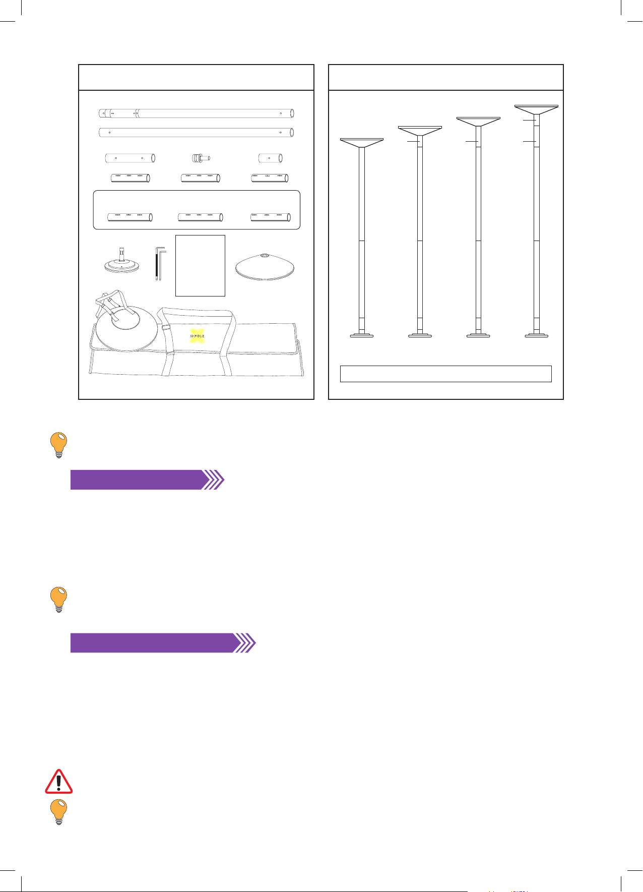
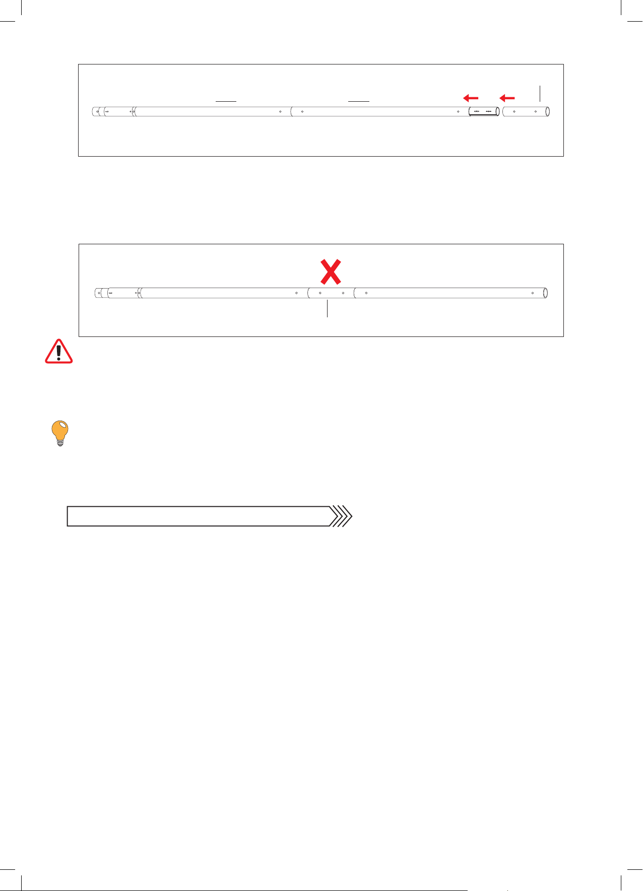
Prior to installation, all shrink-wrap covering the pole tubes and parts must be removed. Please DO
NOT use a sharp instrument/knife to do this, as damage may be caused.
Follow the simple but explicit instructions in this manual to get the best results from your X-POLE XPERT.
Safety is a priority at all times.
If you have ANY questions – before you assemble, install or use your XPERT Pole – contact your point of
purchase or see the X-POLE XPERT section on the website (www.xpole.com – first select your region, then
search for the XPERT Section).
ALL REMOVEABLE AND PORTABLE POLES USE PRESSURE BETWEEN THE FLOOR AND CEILING TO KEEP
THEM STABLE. THERE IS A POSSIBILITY THAT DAMAGE COULD BE CAUSED TO THE CEILING.
VERTICAL LEISURE LTD, X-POLE INTERNATIONAL, X-POLE US INC, THEIR DISTRIBUTORS, SALES PERSONS OR
ANY OTHER PERSONS OR ASSOCIATED COMPANIES CANNOT BE HELD RESPONSIBLE FOR ANY DAMAGE
TO PROPERTY OR INJURY TO PERSONS OR THIRD PARTIES DURING THE USE OF THIS PRODUCT.
BY REMOVING THE XPERT POLE FROM ITS PACKAGING AND/OR ANY USE OF THE PRODUCT CONFIRMS
ACCEPTANCE OF THE ABOVE WARNINGS AND THE USER’S RESPONSIBILITY IN USING THE PRODUCT.
IF YOU DO NOT ACCEPT THE TERMS SET OUT ABOVE THEN:
DO NOT REMOVE THE XPERT POLE FROM ITS PACKAGING OR ATTEMPT TO ASSEMBLE, INSTALL OR USE
THE PRODUCT.
Contact your point of purchase to arrange a return & refund (shipping costs may still apply). The product must
be returned unused & in its fully packaged state.
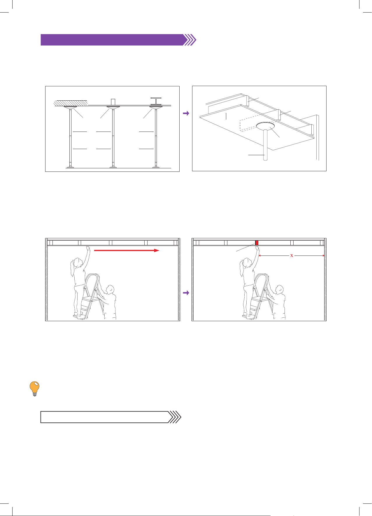
CAUTION: The XPERT Pole SHOULD NOT be installed under false, suspended or non-rigid ceilings.
When searching for Joists please use a step ladder and have a second person holding the ladder providing
additional assistance.
CAUTION: Take note that carpet, wooden or sprung floors can affect the stability of this product.
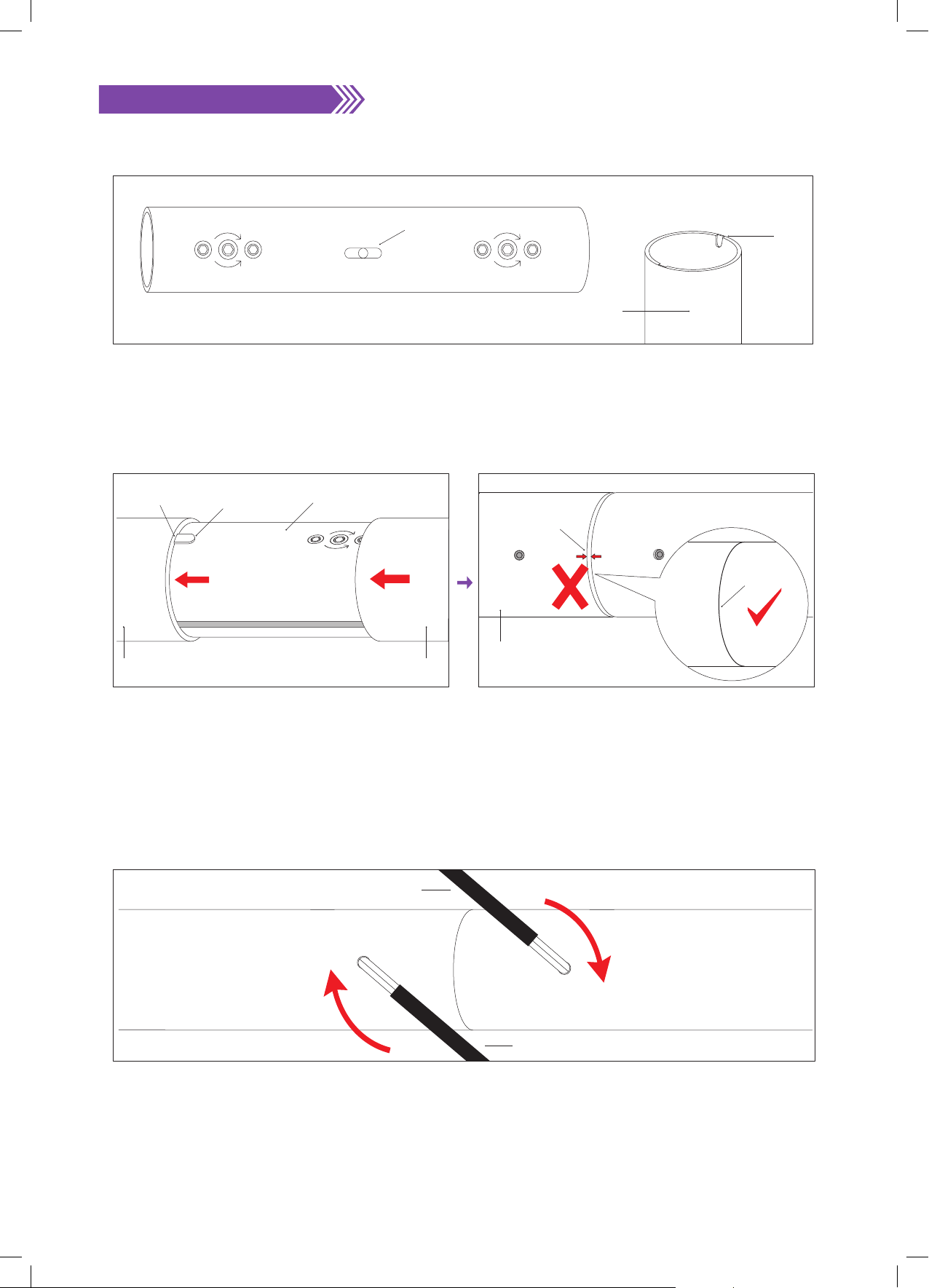
CAUTION: Never undo any of the screws unless you are explicitly told to do so in the instruction manual.
WANT A QUICKER WAY TO ASSEMBLE YOUR XPERT POLE?
WHY NOT SCAN THE CODE TO GO DIRECT TO OUR YOUTUBE
CHANNEL TO WATCH THE INSTALLATION VIDEO – Search for the
‘XPERT Installation’ Video.

2235 - 2375mm
88” - 93.5”
7’ 4”- 7’ 9½”
2360 - 2500mm
93” - 98.5”
7’ 9”- 8’ 2½”
2485 - 2620mm
98” - 103.25”
8’ 2”- 8’ 7¼”
2610 - 2745mm
102.75” - 108”
8’ 6”- 9’
125mm
250mm250mm125mm
Sizes achievable using the 125mm & 250mm extensions
X-POLE XPERT Height Chart
Fig. [1.1] Fig. [1.2]
A-Pole
B-Pole
Extension 250mm (10”)
X-Joint 200mm (8”) X-Joint 200mm (8”) X-Joint 180mm (7”)
Extension 125mm (5”)
Top Adapter
Carry & Storage Cases
Box Contents
(40, 45, 48, 50 & 53mm) Pole set
These X-Joints only apply to the 40 & 48 mm Pole sets
X-Joint 250mm (10”) X-Joint 250mm (10”) X-Joint 200mm (8”)
Upper Dome
Instruction Manual
6mm/5mm
Hex Key
Base
Instruction manual
X-POLE
XPERT
LEADER IS POLE & AERIAL FITNESS
®
WHAT YOU NEED BEFORE YOU START: 1 x Tape Measure & 1 x Spirit Level
TIP: Measurement Calculation: 100mm = 10cm = 3.94 inches (or divide the amount of millimetres
by 25.4 to get inches)
CHECKING THE PARTS
Please check the contents of your XPERT pole with the contents diagram (Fig 1.1). If anything is missing or
damaged, please contact your point of purchase or call your local X-POLE office immediately (contact details
on the back page).
Please study the contents and the part descriptions in the diagram [Fig 1.1] as these are used throughout the
instruction manual and are important for installation. Please also try using the parts before assembling, it is
important that you understand how they work.
TIP: FOR TRANSPORT & DELIVERY THE X-Joints ARE INSTALLED INSIDE THE EXTENSIONS.
X-POLE XPERT HEIGHT CHART
Using the full allowed length (125mm/5”) of the Screw Adjuster (which adjusts the height of the pole) &
both supplied extensions (125mm/5” & 250mm/10”) will allow the XPERT to fit ceilings between the ranges of
2235mm (88”) to 2745mm (108”). If you have a ceiling which is higher than 2745mm (108”), you will need
to purchase additional/optional extensions from our website www.xpole.com (first select your region, then
search for the ‘Extensions’ section) or from your point of purchase.
The Screw Adjuster has the capability of extending the XPERT pole by 125mm (5”). With the Screw Adjuster
closed (contracted) you will be able to achieve a height of 2235mm (7’4”) & with it open (extended) using both
the supplied extensions, you will achieve a height of 2745mm (9’).
CAUTION: You should NEVER use more than 125mm (5”) of the Screw Adjuster.
TIP: Ceilings over 3.35m/11ft will require mounts or ceiling plates - please see pg.15. If you have
any doubts about the height you wish to reach, contact your local X-POLE office or Point of Purchase.
Copyright© Vertical Leisure LTD 2014 All rights reserved. Version: 1.01
4

Copyright© Vertical Leisure LTD 2014 All rights reserved. Version: 1.01
5
TIP: Joists can be located using an optional Joist/stud finder; this can be purchased from most
hardware stores.
NEXT: FINDING A SUITABLE DANCE AREA
Once a Joist is located, take a position measurement
from the wall for future reference. Write this
measurement here: X= _________________
Make sure that the measurement is taken at 90°
from the Joists.
Fig. [2.4]
To find a Joist above your ceiling, tap across the
ceiling with your knuckle until a solid sound is heard
– this will be the Joist. If you keep tapping across the
ceiling the sound will become hollow – the space
between the Joints.
Fig. [2.3]
Ceiling Joist
3. 4.
Fig. [2.1] Fig. [2.2]
Ceiling
Joist
Joist
Upper Dome
Pole
LOCATING CEILING JOISTS:
CHOOSING THE BEST PLACE FOR YOUR X-POLE
Try to find a suitable area in the centre of your room, where you would like to install your pole.
Above this area, you will need to locate a ‘Joist’, please see instructions below on how to do this.
Soild Ceiling Single Joist Steel Girder
Upper Dome Upper Dome
B-Pole B-Pole
A-Pole A-Pole
Joists are beams of wood that run from wall to wall
and support your ceilings. The Upper Dome must be
centred under the Joist.
The XPERT POLE should be installed in the most
secure location possible, like under a solid ceiling –
if you do not have a solid ceiling, you will have to
locate a ‘Joist’ or ‘girder’ to install the upper dome
against.
1. 2.

Now you have found a suitable exercise area & the ideal spot for the installation of your pole.
Measuring the Height of the Ceiling
Accurately measure the height of the ceiling at the point
of use and match the ceiling height to the pole height
on the chart [Fig 1.2]
TIP: If longer extensions are required (than those
supplied in the standard set), then a key point is to
minimise the number of extensions & Joints used
for a given height requirement; i.e. if the required
extension length is 500mm – it is better to use
[1 x 500mm extension & 1 x X-Joint] rather than
[2 x 250mm extensions & 2 x X-Joints].
FOR CEILING HEIGHTS OVER 3.35M/11FT, PLEASE REFER TO
PG.15. Fig. [4.1]
Tape Measure
Ceiling
Floor
TIP: Measure a circle with a diameter (measured from one point of a circle across to another) of
approximately 3000 – 3500mm (120” – 138”) and locate your pole in the centre of the circle.
Fig. [3.3] Fig. [3.4]
Place a chair beneath the location where you have
identified your Joist OR imagine a fully assembled
pole beneath this spot.
Fully stretch both your arms & place one hand on
the chair/imaginary pole and walk around it in a
circular motion.
Fig. [3.1] Fig. [3.2]
1.5m min
FINDING A SUITABLE EXERCISE & DANCE AREA
Copyright© Vertical Leisure LTD 2014 All rights reserved. Version: 1.01
6
Floor
Chair
1. 2.
Whilst rotating around the chair/imaginary pole you
must not hit or touch anything else in the room.
This area will enable you to fully extend your arms
& legs when using the pole. ADDITIONAL HELP ON
pg.15.
3. 4.
NEXT: HOW TO USE THE X-JOINT

HOW DOES X-POLE’S X-JOINT WORK?
X-POLES use a revolutionary joint called the X-Joint that expands inside the pole tubes to lock them together
and stops them from coming apart/separating. To optimise the X-Joint’s key features and ensure correct
operation, it is important that you carefully follow these instructions.
X-JOINT OPERATION: PLEASE NOTE: ANTI-CLOCKWISE = COUNTER CLOCKWISE
Copyright© Vertical Leisure LTD 2014 All rights reserved. Version: 1.01
There are 3 sizes of X-Joints; 180mm (7”), 200mm
(8”) & 250mm (10”).
The 180mm (7”) X-Joint has one half longer than
the other & is marked with an arrow (on the shorter
end), when used, this must be installed at the top
with the arrow pointing upwards.
180mm X-Joint
Fig. [5.1]
EXPAND
CONTRACT
EXPAND
CONTRACT
EXPAND
CONTRACT
EXPAND
CONTRACT
EXPAND
CONTRACT
EXPAND
CONTRACT
EXPAND
CONTRACT
180mm (7”)
200mm (8”)
250mm (10”)
7
Always remember:
TO EXPAND/TIGHTEN: Clockwise
TO CONTRACT/LOOSEN: Anti/Counter-Clockwise
Fig. [5.5]
Pole Tube
CLOCKWISE to
EXPAND/TIGHTEN
ANTI/COUNTER-
CLOCKWISE to
CONTRACT/LOOSEN
Hex Key
TIP: Before pole installation test the
operation of the X-Joint on its own and
then on 2 x Extension Tubes. It is better to
loosely tighten the X-Joints and then undo
and firmly re-tighten them when the pole
is in place, as when vertical, the weight/
pressure of the pole tubes will push the
Joints tightly together.
CAUTION: The 180mm X-Joint
(200mm in the case of 40mm &
48mm poles) should only be used
with the 125mm extension.
NEXT: ASSEMBLING YOUR X-POLE
125mm
250mm
200mm - XJ
200mm - XJ
B-Pole
A-Pole
1. 2.
The X-Joint features a special mechanism which
expands/contracts to lock/loosen the pole tubes
together. Please test this prior to assembly.
Fig. [5.3]
Hex Key
Pole Tube
X-Joint
The Joint expansion is done by FULLY inserting the
6mm Hex Key (with black plastic cover) into the pole
tube & rotating clockwise.
Fig. [5.4]
Hex Key
Pole Tube
X-Joint
Fully Inserted
3. 4.
5.
Fig. [5.2]
Key
Arrow Mark
EXPAND
CONTRACT
EXPAND
CONTRACT
40mm: 1 x 200mm (8”) 2 x 250mm (10”)
45mm: 1 x 180mm (7”) 2 x 200mm (8”)
48mm: 1 x 200mm (8”) 2 x 250mm (10”)
50mm: 1 x 180mm (7”) 2 x 200mm (8”)
53mm: 1 x 180mm (7”) 2 x 200mm (8”)
The XPERT Pole is supplied with:

Copyright© Vertical Leisure LTD 2014 All rights reserved. Version: 1.01
ASSEMBLING YOUR X-POLE
Connecting the A-POLE (main tube with screws & screw adjuster at one end) to the B-POLE.
1. At the centre of the X-Joint are 2 x Keys. These Keys slide into the corresponding U Keyway slots in the pole
tube.
Fig. [6.1]
X-Joint
Pole Tube
U Keyway Slot
Key
EXPAND
CONTRACT
EXPAND
CONTRACT
8
Fig. [6.4]
A Pole
Hex Key
B Pole
CLOCKWISE to TIGHTEN
Hex Key
It is important to tighten the screws progressively – alternating between the screws, tightening Clockwise.
This will ensure the pressure is equalised within the pole tubes.
4.
Insert a 200mm X-Joint into the A-Pole ensuring
the keys locate into the U Slots and the expansion
screws line up with the holes on the pole tubes.
Next attach the B-Pole to the A-Pole with the X-Joint
ensuring the Keys engage with the U Keyway Slots.
Fig. [6.2]
Check the tube edges are tight together – then
loosely tighten the screw in the A-Pole – now loosely
tighten the other tube (B-Pole) – continue to tighten,
alternating between the two until no further force
could be applied to the screws.
Fig. [6.3]
X-Joint
Key
U Keyway Slot
A-Pole B-Pole
EXPAND
CONTRACT
Visible Gap
A-POLE
B-POLE
No Gap
2. 3.

NEVER INSTALL EXTENSIONS IN THE MIDDLE OF THE POLE – THIS IS DANGEROUS.
Fig. [6.6]
A Pole B Pole
EXTENSION
TIP: If longer extensions are required (than supplied in the standard set), then a key point is to
minimise the number of extensions & Joints used for a given height requirement; i.e. if the required
extension length is 500mm – it is better to use [1 x 500mm extension & 1 x X-Joint] rather than [2 x
250mm extensions & 2 x X-Joints].
Copyright© Vertical Leisure LTD 2014 All rights reserved. Version: 1.01
9
NEXT: HOW TO ATTACH THE BASE TO THE A-POLE
Then, as required, keep adding X-Joints and Extensions to reach your desired height – minimising the number
of Joints and tubes by using optional longer extensions (available from our online shop; www.xpole.com - first
select your region, then search for ‘Extensions’) where possible.
These tubes are always installed together
A Pole B Pole
X-JOINT EXTENSION
Fig. [6.5]
5.
Install Extensions at the top of the Pole.

TOP ADAPTER UNIT ATTACHMENT
Once the A-Pole and B-Pole (and any additional extensions) are connected, insert the Top Insert into the
B-Pole or last extension used then slide the upper dome onto the top insert.
BE CAREFUL WHEN YOU LIFT THE ASSEMBLED XPERT POLE, TO INSTALL, THAT THE UPPER DOME DOES
NOT FALL OFF, AS IT IS LIFTED INTO POSITION.
Fig. [7.4]
ExtensionA Pole B Pole Top Insert
Upper Dome
1.
HOW TO ATTACH THE BASE TO THE A-POLE
CAUTION: DO NOT FORGET: If you are using extensions, you can ONLY use a 180mm X-JOINT
(200mm in the case of 40mm & 48mm poles) with a 125mm extension and make sure the ARROW is
always pointing towards the ceiling.
Copyright© Vertical Leisure LTD 2014 All rights reserved. Version: 1.01
10
Fig. [7.3]
Base
Hex Screw
Hex Key
Adjuster Body
X Mark
X
CLOCKWISE to TIGHTEN Once the A-Pole is on the shaft – align both
the Static/Spin screws with the ‘X-Marks’ on the
base and tighten the 2 screws.
3.
Fig. [7.1]
Base Shaft
Base
Flat SectionFlat Section
X MarkX Mark
XX
The 2 x flat sections are where the hex screws will
locate to stop the pole from spinning. Note the
2 x flat sections on the base shaft, and ensure these
are in line with the X’s on the base.
1. Make sure the 2 x Static/Spin screws are fully
loosened using the 5mm Hex Key. DO NOT
completely remove the screws. Slide the base shaft
into the A-Pole. The two screws need to be in line
with the X’s on the base to ensure they are screwed
onto the flat sections.
2.
Fig. [7.2]
Static/Spin Screw
Static/Spin Screw
Base Shaft
Flat Sections
Base
X Mark

INSTALLING XPERT
CAUTION: When assembled, the XPERT Pole is heavy and at full height, NOT easy to handle. It is
therefore MANDATORY/COMPULSORY that 2 people install the XPERT Pole – i.e. 2 people should lift
it into position and 1 person hold the pole while the other rotates/expands the height adjuster.
Make sure that the base of the pole is at the centre point of your dance area – as explained in ‘Finding a
suitable exercise & dance area’ [Fig 3.1-3.4] and under the selected Joist [Fig 2.4].
Copyright© Vertical Leisure LTD 2014 All rights reserved. Version: 1.01
11
1.
With one person holding the base, the other person
should slowly and carefully lift the pole, raising it
until it is vertical and under the Joist.
Fig. [8.1]
Ceiling
Joist
2. Now undo the 3 Adjuster Locking Hex Screws on
top of the Adjuster Cover with the 5mm Hex Key - a
minimum of 2 whole turns. (DO NOT completely
remove the screws).
Fig. [8.2]
3.
Adjuster Cover
ANTI/COUNTER-
CLOCKWISE to
LOOSEN
3 x Adjuster Locking
Hex Screws
Once vertical, with the second person still holding
the base, rotate the pole, Anti/Counter-clockwise
(i.e. rotate left to right) which will expand the pole
until it touches the ceiling.
Fig. [8.4]
Ceiling Joist
Anti/Counter-Clockwise
Tighten/Expand
Pole Expansion: Rotating the main pole tube from
left to the right (Anti/Counter-Clockwise) will
Expand/Tighten the Pole. Rotating the pole tube
from right to the left (Clockwise) will Shorten/Loosen
the Pole.
Fig. [8.3]
Base
Anti/Counter-Clockwise
Tighten/Expand
4. 5.
Once the Upper Dome is against the
ceiling and before it is tightened further,
make sure that the pole is vertical. Best
way to do this is using a ‘spirit-level’ (which
can be purchased from a local hardware
store) or visually align the pole with a door
or window frame.
Fig. [8.5]
6.

Copyright© Vertical Leisure LTD 2014 All rights reserved. Version: 1.01
12
If the pole is not vertical, move the base in the
required direction. DO NOT move the Upper Dome
which must be kept over the centre of the Joist at all
times.
Fig. [8.7]
It is critical that the Upper Dome is flat against the
ceiling/Joist. DO NOT expand the adjuster further
until the upper dome is flat against the ceiling/Joist.
If the Upper Dome is not flat, the plate could rotate,
and slip or damage the ceiling.
Fig. [8.6]
7. 8.
Tighten the XPERT pole until good positive pressure
is felt and the pole is firmly in place. DO NOT exert
too much pressure. Rock/Shake the pole to ensure it
does not move from its position. Now change pole
mode to ‘Spin’ (see Static & Spinning section on
pg.12), spin the pole gently with your hands, if the
pole rotates smoothly, your pole has been tightened
correctly. If the pole DOES NOT rotate smoothly,
it has been OVERTIGHTENED. In this instance, re-
tighten the Static/Spinning screws and loosen the
pole half-a-turn. Repeat until pole rotates smoothly.
Fig. [8.8]
Firm Pressure Too Much Pressure
Damaged
When expanding/unwinding the pole Anti/Counter-
clockwise, the adjuster cover will rise. If a horizontal
line on the adjuster is exposed in the keyhole – this
indicates that the adjuster is close to 100mm. It is at
100mm when the line is below the adjuster cover.
Consider buying an extension from our website
www.xpole.com
Fig. [8.9]
Vertical Line
Horizontal Line
Adjuster Cover Keyhole
Anti-Clockwise
Adjuster Body
Adjuster Cover
9. 10.
Vertical Line
Adjuster Cover
Keyhole
Horizontal Line
Black ‘O’ Ring
Adjuster
Adjuster Cover
If ANY of the black ‘O’ ring is exposed, the
adjuster is at its maximum allowed length
(125mm/5”). It is now mandatory/compulsory
to purchase an additional extension, available
from our website www.xpole.com or your Point
of Purchase.
DO NOT exceed the point past the ‘O’ ring.
Fig. [8.10]
11.

Copyright© Vertical Leisure LTD 2014 All rights reserved. Version: 1.01
13
TIP: If the floor is not solid (concrete), it helps, once the pole is tight, to have someone stand on the base and
then re-tighten. This compresses the floor and also makes it easier to rotate the pole.
Once the pole is tight, rotate the pole till the
Adjuster Cover Keyhole is in alignment with the
vertical line on the Adjuster. This will ensure that
the screws are on the flats. Now tighten the 3
Adjuster Locking Hex Screws tightly with a 5mm
Hex Key to lock the A-Pole.
Fig. [8.11]
3x Adjuster Locking
Hex Screws
Adjuster Cover Keyhole
Adjuster Cover
Adjuster
Vertical Line
12.
STATIC & SPINNING
To change the pole mode from static to spinning –
undo the 2 x Static/Spin Hex screws at the bottom
of the pole, until they are flush with the pole - DO
NOT REMOVE COMPLETELY – the pole will now spin
freely.
To return to static, rotate the pole till one of the hex
screws is in alignment with the ‘X’ on the base plate
and FULLY tighten. Whilst tightening, gently rotate
the pole back and forth to help seat the screw. Now
fully tighten the other screw.
Fig. [9.1] Fig. [9.2]
Hex Screw loosened
too much
Hex Screw flush with
outer suface
Static/Spinning Mode Adjuster Body
Base
X Mark
X Mark
XX
Hex Screw tighten
against base shaft
Static/Spinning Mode
X Mark
X
Base
Adjuster Cover
Adjuster Body
Adjuster Cover
1. 2.
13.Once the pole feels tight and does not move, try
practicing a turn with at least one feet on the floor.
Re-tighten as necessary until there is no movement.
Once you are certain that the pole has been
installed safely - try a move with your feet off the
ground.
Your XPERT pole is now ready for use.
Fig. [8.12]
1 2
CAUTION: Do not over-tighten the XPERT Pole - only tighten till good positive pressure is felt and the
pole is firmly in place.

Copyright© Vertical Leisure LTD 2014 All rights reserved. Version: 1.01
14
CLEANING YOU XPERT POLE
POLE MAINTENANCE & REMOVAL
Because the XPERT pole uses pressure to remain
in position. The pole tightness should be checked
regularly during use, ideally every 30 minutes.
If there is any movement, DO NOT USE, until
you have re-tightened. Always check the
X-Joints at the same time.
To take down the pole, undo the 3 x Hex Adjuster
Locking Screws (DO NOT completely remove the
screws). Then turn the pole clockwise to contract/
release the pole. Once the pole has been removed
from its position, the Upper Dome & Base can be
removed.
Fig. [10.1]
Anti/Counter-Clockwise
Tighten/Expand
Fig. [10.2]
Clockwise
Loosen/Shorten
3x Hex Screws
1. 2.
CAUTION: STORE YOUR XPERT POLE ONLY IN A WARM, DRY PLACE.
Lay the pole tubes on the floor and undo the X-Joints to disassemble the XPERT. To undo the X-Joint – turn both
Hex Screws Anti/Counter Clockwise – undo screws until there is pressure against the key.
Fig. [10.3]
Hex Key
Hex Key
ANTI/COUNTER - CLOCKWISE to
LOOSEN
A Pole B Pole
3.
Fig. [11.1]
X-CLEAN & Micro-Fibre Cloths
X-POLE strongly recommends the use of X-CLEAN
with our specially designed Micro-Fibre Cloths to
clean and maintain the surface of your XPERT Pole.
You can purchase these items from our website
www.xpole.com (first select region, then search for
X-CLEAN) or your Point of Purchase.
DO NOT USE X-CLEAN on Powder Coated or
Silicone Poles.
The Perfect Solution

Copyright© Vertical Leisure LTD 2014 All rights reserved. Version: 1.01
15
ACCESSORIES
TIP: When installing multi-piece poles over 3.35m/11ft, it is mandatory to install a Ceiling Plate or Ball Mount.
It is also strongly recommended not to use standard multi-piece poles and to use our ‘Competition Poles’ in
this scenario. Please contact your local X-POLE office, or your Point of Purchase for further details.
For ceiling heights over 3.35m/11ft, it is mandatory/compulsory to use a Ceiling Plate or Ball Mount.
Ceiling Plate
The Ceiling Plate is a permanent fixture which will
prevent any movement of the Upper Dome when
using multi-piece poles over 3.35m/11ft.
For further details please visit our website at www.
xpole.com or contact your Point of Purchase.
Ball Mount
The Ball Mount is a permanent fixture which will
prevent any movement of the complete pole when
using multi-piece poles over 3.35m/11ft. The Ball
Mount replaces the need for an Upper Dome.
For further details please visit our website at www.
xpole.com or contact your Point of Purchase.
Fig. [12.1]
Ceiling Joist
Ceiling Plate
Upper Dome
Extension
B-Pole
Fig. [13.1]
ADDITIONAL ASSISTANCE SECTION:
PLEASE NOTE: ANTI-CLOCKWISE = COUNTER CLOCKWISE
As damage can occur from the pressure used to keep the XPERT Pole in place, it is mandatory that
the pole is centred under one Joist. The better aligned the upper dome is under the centre of the
Joist and the more care taken in assembly and set-up, the less potential there is for damage.
Most plasterboard or plaster ceilings, will flex/compress with pressure. This means that the retaining
nails/pins/screws can be pushed out of the plasterboard when pressure is applied by the pole
adjuster. If this happens, just re-nail or re-tighten the fixing screws, fill and re-paint.
Dance moves can be performed by experienced dancers in a smaller space than recommended but
for beginners the above space is mandatory. Once you have located the correct sized clear area you
can look for the ceiling Joists above the area you have selected.
A.
B.
C.
Other manuals for Xpert
1
Table of contents
Other X-pole Fitness Equipment manuals
Popular Fitness Equipment manuals by other brands

AVIVA
AVIVA Iceberg Climbing Wall Instructions & warnings

SportsArt Fitness
SportsArt Fitness DF-200 owner's manual

Weider
Weider WEBE06110 user manual

FITFIU FITNESS
FITFIU FITNESS BESP-250 instruction manual

KingsBox
KingsBox Kings Bar II. EU Bar manual

Peak Pilates
Peak Pilates MVe Chair Assembly & user's guide