Xray NT1 Product guide

®

2
CONTENTS
Setting Up the XRAY NT1 3
Set-up Order 4
Terminology 4
Weight Transfer 5
Weight Balance 5
Center-of-gravity 5
Downstops 5
Effects of Downstop Adjustment 6
Measuring Downstops 6
Adjusting Downstops 7
Shock Absorbers 8
Shock Spring Rate 8
Effects of Spring Rate Selection 8
Shock Spring Preload 9
Shock Position 9
Effects of Shock Position Adjustment 9
Adjusting Shock Position 9
Shock Damping 10
Effects of Shock Damping Adjustment 10
Adjusting Shock Damping 11
Track-width 11
Effects of Track-width Adjustment 12
Measuring Track-width 12
Adjusting Track-width 12
Ride Height 13
Effects of Ride Height Adjustment 13
Ride Height and Tires 13
Ride Height and Suspension Settings 13
Measuring Ride Height 13
Adjusting Ride Height 14
Camber 14
Measuring Camber 15
Adjusting Camber 15
Caster 16
Effects of Caster Adjustment 16
Adjusting Caster 17
Toe 17
Effects of Toe Adjustment 17
Measuring Toe 17
Adjusting Toe 18
Anti-roll Bars 19
Effects of Anti-roll Bar Adjustment 19
Adjusting Anti-roll Bars 19
Tweak 20
Combating Tweak 20
Measuring & Correcting Tweak 21
XCA Clutch 23
Building and Maintaining the XCA Clutch 23
Flywheel Shimming 24
Adjusting Flywheel Distance 24
Clutch Spring Preload 24
Effects of Clutch Spring Preload 24
Adjusting Clutch Spring Preload 24
Clutch Gap 25
Effects of Clutch Gap Adjustment 25
Adjusting Clutch Gap 25
Clutchbell Endplay 25
Effects of Excessive Clutchbell Endplay 25
Adjusting Clutchbell Endplay 26
Clutch Shoes 26
2-speed Transmission 26
Shift Point 26
Adjusting Shift Point 27
Transmission Shoe Gap 27
Adjusting Transmission Shoe Gap 27
Multi-Flex Technology™ 28
Effects of MFT™ Adjustment 28
Adjusting Chassis Stiffness
with MFT™ 1-piece Engine Mount 28
Roll Center 29
Roll Center Basics 29
Roll Center in Action 29
Effects of Roll Center Adjustment 29
Adjusting Roll Center 30
Camber Rise 32
Adjusting Camber Rise 32
Steering Ackermann 33
Adjusting Ackermann 33
Front and Rear Axles 34
Gear Differentials 34
Effects of Gear Differential Adjustment 34
Adjusting the Gear Differentials 34
Solid Front Axle 35
XRAY Multi-diff™ 35
Gearing 36
Drivetrain Ratio (DTR) — Internal Ratio 36
Primary Drive Ratio (PDR) 36
Final Drive Ratio (FDR) 37
Overdrive Ratio (ODR) 37
Rollout 37
Overdrive Ratio, Rollout, and Tire Size 37
Shock Building Tips 38
Periodic Shock Maintenance 38
Fill and Bleeding Process 38
Foam Tire Tips 39
Bearing Maintenance 39
Martin Hudy, Junior Designer at XRAY R&D, guides you through the set-up theory of the XRAY NT1 and
discloses all the tips & tricks to make your NT1 a winning car.
All texts and images contained within this set-up book are copyright by XRAY. All rights reserved. ©2007 XRAY

3
SETTING UP THE XRAY NT1
Setting up a nitro-powered racecar with fully-independent suspension, clutch, and multi-speed transmission — like your XRAY NT1 — is necessary
to make the car perform well. We have developed the NT1 Setup Book to help you set up your NT1 properly and easily. Follow the procedures
carefully, and always make sure that you make equal adjustments on left and right sides of the car.
In addition to describing how to measure and adjust your NT1, the NT1 Setup Book contains detailed information about the effects of setting
adjustments so that you will have a better understanding of them.
Throughout the NT1 Setup Book, we refer to handling effects of the car in the corner, and distinguish three corner sections and three throttle/
brake positions as follows:
Car setup is a complex matter, as all adjustments interact. Fine-tuning your car’s setup will make it faster and often easier to drive near its
performance limit. This means that all the effort you put into preparing your NT1 and optimizing its setup will help pay off in better performance,
results, and satisfaction.
Chassis stiffness (especially torsional) is an important factor when setting up your car. A stiff chassis helps to eliminate chassis flexing and twisting,
which would otherwise introduce another factor that is not easy to measure or adjust. However, chassis stiffness is also a setup tool. By altering
chassis stiffness (for example, using a different engine mount) you can make a “softer” or “stiffer” car that may be more or less suited to track
conditions or driving style. The NT1 features the exclusive XRAY Multi-Flex Technology™ engine mounting system which enables you to adjust the
chassis stiffness.
If you choose to adjust the setup of your NT1, make small adjustments one at a time, and see if you find any improvement in performance and/or
handling with each adjustment. We advise you to keep track of your setup changes, and record which setups work best at different racetracks under
various conditions. You can upload your NT1 setup settings to the XRAY Online Virtual Setup Sheet Database at www.teamxray.com and access your
personal settings from anywhere in the world at any time. You can also benefit from all the setup sheet knowledge and download setup sheets from
XRAY factory team drivers.
Remember that for your NT1 to work and respond to setup changes properly, it must first be in good mechanical shape. Check the well functioning
of critical areas such as the free movement of the suspension, smoothness of shock absorbers, and adjustment and wear of clutch and transmission
parts after each run (and especially after a collision).
After rebuilding the chassis, or in case you become lost with your setup, always return to the last setup you have recorded, or use one of the NT1
setups posted by others.
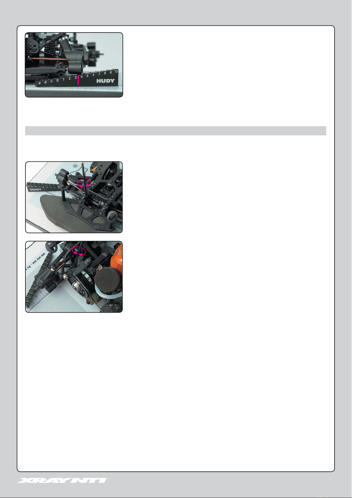
When setting up your NT1, we strongly recommend using the HUDY All-In-One Set-Up Solution #108255,
a high-precision professional set-up system that includes all necessary setup tools and equipment.
107702 DROOP GAUGE SUPPORT BLOCKS
• CNC-machined high-grade aluminum
• precision engraving
• supports chassis when checking downstops
• used with 107712 Droop Gauge
109305 UNIVERSAL EXCLUSIVE ALU. SET-UP SYSTEM FOR TOURING CARS
• CNC-machined alu. and acrylic components
• fully ball-bearing equipped
• precision engraving
• directly measures camber, camber rise, caster, toe, steering throw symmetry
•
easy one-screw assembly/disassembly
PROFESSIONAL TWEAK STATION FOR 1/10 TOURING CARS
• best-in-class integrated solution for
quick and easy track & tweak adjustment
• innovative, easy-to-use, high-tech design
• fully ball-bearing equipped for smoothness and high precision
• ultra-sensitive balance platform gives highly-accurate readings, allowing you to easily and quickly read
and interpret tweak
• rugged CNC-machined aluminum construction, fully assembled
SETTING UP THE XRAY NT1
Corner sections: Throttle/brake positions:
• corner entry • braking
• mid-corner • off-throttle
• corner exit • on-throttle

4
The terms “understeer” and “oversteer” appear throughout this manual. These terms describe a particular handling characteristic of the car.
Understeer
Also known as “push.”
A car understeers when the front wheels do not grip enough and the rear tires grip too much. This results in a front end that slides too much rather
than turning. A car that understeers is easier to drive, but it is slower than a car that oversteers slightly.
Oversteer
Also known as “loose.”
A car oversteers when the front wheels grip too much and the rear tires do not grip enough. This results in a rear end that slides too much.
Excessive oversteer causes the rear tires to “break loose” allowing the car to spin out.
TERMINOLOGY
SET-UP ORDER
The table below gives you a breakdown of the following:
• recommended order of setup
• car components to be attached/detached for a particular setting
• setup components to be used for a particular setting
We recommend setting up your NT1 chassis in the order indicated in the table below. The order of the chassis settings has been determined
as the most logical to set up your NT1 chassis properly and easily. Also, certain chassis settings must be made before others, as changing one setting
will impact another setting.
107715 RIDE HEIGHT GAUGE
• CNC-machined high-grade aluminum
• precision engraving
• measures ride height
108211 SET-UP BOARD DECAL
• self-adhesive set-up decal for 108201 Set-Up Board
• accurate, clear markings with 1mm grid for adjustment of 1/10 touring cars
• tough, smooth, liquid-resistant plastic surface
108201 SET-UP BOARD
• suitable for 1/10 R/C touring cars
• exceptionally flat, warp-resistant surface
• very small, compact size
• provides perfectly flat reference surface
for chassis set-up
SETTING UP THE XRAY NT1
107712 DROOP GAUGE
• CNC-machined high-grade aluminum
• precision engraving
• measures downstops when used with107702 Droop Gauge Support Blocks
✔: Attach / Use ✘: Detach / Do Not Use
SETTING Page CAR COMPONENTS SETUP COMPONENTS
Shocks Anti-roll
Bars
Wheels Setup
Stands
Droop
Gauge Set
Ride
Height
Gauge
Toe Gauge Flat Board
& Decal
1. Downstops 5✘✘✘ ✔ ✔
2. Track-width 11 ✔✔ ✔
3. Ride Height 13 ✔✔✔ ✔✔
4. Camber 14 ✔✘✘✔ ✔
5. Caster 16
6. Toe 17 ✔✘✔ ✔✔
7. Tweak 20 ✔✘/ ✔✔ ✔

5
Weight transfer is the key to car handling. Consider that a car has a certain amount of “weight” on various parts of the car and this weight is
distributed by a certain amount into each wheel.
• When the car corners, weight is transferred to the outside tires
• When the car accelerates, weight is transferred to the rear
• When the car brakes, weight is transferred to the front.
By transferring weight to one side of the car (left or right) or one end of the car (front or rear), the tires on that side (or at that end) will be forced onto
the racing surface more, resulting in more grip or traction at that side/end. The amount of weight transfer is affected by the car’s center-of-gravity
(CG), distribution of the weight by the car’s setup, and the way you drive.
Before you start adjusting your car’s setup, you should ensure the following:
• Car is in good mechanical shape with no broken, binding, or loose parts
• Car has proper weight balance front/rear and left/right
You should always try to adjust the weight on your car so it is equal left-to-right — this will help to ensure proper, consistent handling. You can use
balancing tools to check the weight distribution of your car, and ensure that your ready-to-race car does not list to one side.
We recommend using the #107880 HUDY Chassis Balancing Tool.
The center-of-gravity (CG) of the car is the point on the car (in 3 dimensional space) around which the car moves, and the point at which all force is
applied while the car is in motion.
• When the car goes around a corner, centrifugal force pushes the car to the outside of the turn, and this force pushes on the car’s CG causing the car
to tilt or roll to the outside. This transfers weight to the outside wheels of the car.
• When the car accelerates, the force pushes backward on the car’s CG, causing the car to tilt backward. This transfers weight to the rear wheels.
• When the car brakes, the force pushes forward on the car’s CG, causing the car to tilt forward. This transfers weight to the front wheels.
Center-of-gravity is affected by the physical weight of the car, and the placement of all components on the car. If the car is not equally balanced
front/rear and left/right, the car’s CG will not be centered. This will cause the car to handle differently when it turns one direction as opposed to the
other direction.
It is always best to make the car’s CG as low as possible to minimize the negative effects of weight transfer. Do this by placing all components as low
as possible on the car’s chassis, and reduce weight high on the chassis.
WEIGHT TRANSFER AND CAR SET-UP
Car setup is always a matter of compromise, and every aspect of car setup affects how weight transfers on the car. There is no one “magical” setup
change that will solve all of your car’s handling problems. Car setup is a complex interaction of the various components that make up the car, and
all of these aspects of setup will affect one another.
WEIGHT BALANCE
WEIGHT TRANSFER
CENTER-OF-GRAVITY
WEIGHT TRANSFER
Downstops limit how far the suspension arms travel downward, which determines how far upward the chassis rises. This affects the car’s handling
(due to effects on camber and roll-center) and the ability of the tires to “follow” the track. The effects may change with the type of track and/or
amount of grip available.
More suspension travel (lower downstop value) makes the car more responsive but less stable; it is also typically better on a bumpy tracks or tracks
with slow corners. Less suspension travel (higher downstop value) makes the car more stable and is typically better on smoother tracks.
It is very important to have the same downstop settings on the left and right sides of the car.
DOWNSTOPS
FRONT DOWNSTOP
FRONT DOWNSTOP
REAR DOWNSTOP
REAR DOWNSTOP

6
2. Lift and drop the suspension arms so that they settle in their lowest positions.
3. Using the droop gauge, measure the downstop value from the bottom of the front steering
blocks / rear uprights..
FRONT DOWNSTOPS
Measure at the bottom of the steering block. Do NOT measure under the arm.
Front Downstops
Higher front
downstop value
• Decreases front chassis upward travel on-throttle.
• Increases high-speed steering.
• Increases “initial” on-throttle understeer.
• Better on smooth tracks.
Lower front
downstop value
• Increases upward chassis travel on-throttle.
• Decreases high-speed steering.
• Decreases “initial” on-throttle understeer.
• Better on bumpy tracks.
Rear Downstops
Higher rear
downstop value
•
Decreases rear chassis upward travel off-throttle or under braking.
• Increases stability under braking.
• Better on smooth tracks.
Lower rear
downstop value
• Increases rear chassis upward travel off-throttle or under braking.
• Increases steering in slow corners.
• Better on bumpy tracks.
1. Place the droop gauge support
blocks on the setup board, and
then place the chassis on the
support blocks.
Make sure the chassis is solidly
mounted on the support blocks so it
does not move.
DOWNSTOPS
INITIAL STEPS SET-UP COMPONENTS:
Prepare the car as follows: Use the following set-up components:
• Shocks: Detach the shocks.
• Anti-roll bars: Detach the anti-roll bars.
• Wheels: Remove the wheels.
• Droop Gauge Support Blocks
• Droop Gauge
EFFECTS OF DOWNSTOP ADJUSTMENT
MEASURING DOWNSTOPS

7
Droop Gauge Values
• Positive numbers on the gauge indicate the distance (in mm) ABOVE the top level of the elevating blocks (or, above the bottom of the chassis).
• Negative numbers on the gauge indicate the distance (in mm) BELOW the top level of the elevating blocks (or, below the bottom of the chassis).
REAR DOWNSTOPS
Measure at the bottom of the rear uprights. Do NOT measure under the arm.
ADJUSTING FRONT DOWNSTOPS
Set the front downstops so the bottoms of the steering blocks are at a specific value on the gauge.
Adjust front downstops by turning the downstop setscrews into or out of the front bulkheads.
• INCREASE front downstop:
Turn IN (CW) the front downstop screw so the front lower arm rises.
• DECREASE front downstop:
Turn OUT (CCW) the front downstop screw so the front lower arm drops.
IMPORTANT: Measure the front downstop under the steering block.
ADJUSTING REAR DOWNSTOPS
Set the rear downstops so the bottoms of the rear uprights are at a specific value on the gauge.
Adjust rear downstops by turning the downstop setscrews into or out of the rear lower arms.
• INCREASE rear downstop: Turn IN (CW) the rear downstop screw so they protrude more
below the arms.
• DECREASE rear downstop: Turn OUT (CCW) the rear downstop screw so they protrude
less below the arms.
IMPORTANT: Measure the rear downstop under the rear upright.
DOWNSTOPS
Adjust the front and rear downstops using the downstop setscrews in the front bulkheads and rear lower arms, respectively.
IMPORTANT: Make sure you adjust downstops so they are equal on both left and right sides.
ADJUSTING DOWNSTOPS

8
Shock absorbers, or shocks, are the suspension components that allow the wheels to keep as much
contact as possible with the track surface. The XRAY NT1 has fully-independent front and rear
suspension, meaning that the suspension at each corner of the car (front left, front right, rear left, rear
right) moves and may be adjusted independently of the others. As such, there is a shock absorber at
each corner of the car.
Damping, mounting position, spring tension, and spring preload are all characteristics that determine
how the shock performs.
Spring rate is determined by the characteristics of the spring itself, and NOT by the amount of preload placed on the spring by the preload collars.
Characteristics such as wire material, wire thickness, and other factors determine spring rate. Spring rate is usually expressed as a “spring weight”
number that indicates how much weight (or force) is required to compress the spring by a specific amount. A spring with a higher “spring weight”
number is considered “harder” since it will be more difficult to compress than a spring with a lower “spring weight” number.
XRAY shock springs are color-coded so that all springs of a specific “spring weight” have the same external colour. Note that spring colours are NOT
standardized; an XRAY silver spring will not have the same spring tension as a silver spring from another manufacturer.
Stiffer
springs
• Makes the car more responsive.
• Car reacts faster to steering inputs.
• Stiff springs are suited for tight, high-traction tracks that aren’t too bumpy.
• Usually when you stiffen all of the springs, you lose a small amount of steering, and reduce chassis roll.
Softer
springs
• Makes the car feel as if it has a little more traction in low grip conditions.
• Better for bumpy and very large and open tracks.
• Springs that are too soft make the car feel sluggish and slow, allowing more chassis roll.
Stiffer front
springs
• Increases mid-corner and corner-exit understeer.
• Increases steering under braking.
• Increases the car’s responsiveness, but makes it more “nervous”.
Softer front
springs
• Makes the car have more steering, especially mid-corner and at corner exit.
• Front springs that are too soft can make the car understeer under braking.
Stiffer rear
springs
• Makes the car have less rear traction, but more steering mid-corner and at corner exit. This is especially apparent in long,
high-speed corners.
Softer rear
springs
• Makes the car have more rear side traction mid-corner, through bumpy sections, and while accelerating (forward traction).
SHOCK ABSORBERS
SHOCK ABSORBERS
EFFECTS OF SPRING RATE SELECTION
SHOCK SPRING RATE
Adjust shock spring rate by substituting different shock springs on each pair of front or rear shocks.
IMPORTANT: Each pair of front shocks or rear shocks must use the same shock springs on left and right sides.
308386 XRAY SPRING-SET D=1.7 (25 LB) DARK-BLUE - REAR (4)
308387 XRAY SPRING-SET D=1.8 (30 LB) LIGHT-PURPLE - REAR (4)
308396 XRAY SPRING-SET D=1.7 (28 LB) VIOLET - REAR (4)
308397 XRAY SPRING-SET D=1.8 (33 LB) PURPLE - REAR (4)
338183 XRAY SPRING D=1.7 (25 LB) DARK-BLUE - FRONT (2)
338185 XRAY SPRING D=1.7 (28 LB) VIOLET - FRONT (2)
338186 XRAY SPRING D=1.8 (30 LB) LIGHT-PURPLE - FRONT (2)
338187 XRAY SPRING D=1.8 (33 LB) PURPLE - FRONT (2)
Shock spring rate determines how much the spring resists
compression, which is commonly referred to as the
“hardness” of the spring. Different spring rates determine
how much of the car’s weight is transferred to the wheel
relative to the other shocks. Spring rate also influences
the speed at which a shock rebounds after compression.
Spring rate selection depends on whether the track is fast
or slow, or has high or low grip.

9
PRELOAD SETTING THREADED PRELOAD COLLAR
Increase TIGHTEN collar so it moves DOWN the shock body.
Decrease LOOSEN collar so it moves UP the shock body.
The upper and lower shock mounting positions determine how
much leverage the lower suspension arm has on the shock when
compressing it, and how progressive the suspension is. Different shock
position settings change how the shock reacts to compression.
SHOCK POSITION
SHOCK ABSORBERS
EFFECTS OF SHOCK POSITION ADJUSTMENT
Shock spring preload IS used for:
• Used primarily for adjusting ride height. Adjust the spring
preload collar so you get the desired ride-height when the car is
fully equipped, ready-to-run. For more information, see section
Ride Height.
• Adjusting suspension tweak. For more information, see section
Tweak.
Shock spring preload is NOT used for:
• Spring preload does not alter camber or other suspension
settings or characteristics.
• Spring preload does not alter spring tension. To change spring
tension, switch to a softer or harder shock spring (see Shock
Spring Rate).
SHOCK SPRING PRELOAD
Shocks More Inclined • Makes the spring and damping softer.
• Makes the car more progressive, giving a smoother feel and more lateral grip (side-bite).
Shocks More Upright • Makes the spring and damping harder.
• Makes the car have a more direct feel, but less lateral grip.
Hint: File a small notch on the top of each spring collar so
you can tell when you have adjusted it one full rotation.
Adjust shock position by changing the location of the shock upper mounts on the shocktowers.
ADJUSTING SHOCK POSITION
IMPORTANT: For each pair of front/rear shocks, the shock positions must be the same on left and right sides of the car.

10
SHOCK DAMPING – SHOCK OIL
Shock oil is rated with a “viscosity” number that indicates the thickness of the oil, which determines how much the oil resists flowing and how much
it resists the shock piston moving through it. Shock oil with a higher viscosity (for example, 300cSt oil) is thicker than shock oil with a lower viscosity
(for example, 150cSt oil).
We recommend using only highest-grade XRAY Silicone Shock Oil, which is available in numerous viscosities. XRAY Silicone Shock Oil is specially
formulated to be temperature-resistant and low-foaming for use in XRAY shocks.
SHOCK ABSORBERS
SHOCK DAMPING
Shock damping manages the resistance of the shock to movement, as the internal shock piston moves through the shock oil when the shock
compresses and rebounds.
Damping mainly has an effect on how the car behaves on bumps and how it reacts initially to steering, braking, and acceleration. Damping only
comes into play when the suspension is moving (either vertical wheel or chassis movement or due to chassis roll), and loses its effect when the
suspension has reached a stable position. Without damping, the shock springs would cause the shock to “pogo” or “bounce” (compressing and
rebounding) until it stabilized.
When the shock is compressing or rebounding, the shock oil resists the movement of the piston through it. The amount of resistance is affected by
several factors:
• Viscosity (thickness) of the shock oil
• Restriction of oil flow through the piston (affected by the number of holes in the piston)
• Velocity (speed) of the piston
Damping is affected by both shock oil and shock piston settings; getting the optimum shock damping typically requires “hands on” experience.
Adjusting with... Effect
Shock Oil Piston Holes
FRONT SHOCKS
Softer damping Thinner More holes
• Slower steering response.
• Decreases initial steering at corner entry.
• Increases oversteer at corner exit/under acceleration.
Harder damping Thicker Less holes
• Faster steering response.
• Increases initial steering at corner entry.
• Increases understeer at corner exit/under acceleration.
SHOCK DAMPING – SHOCK PISTONS
Shock pistons affect shock damping by affecting how easily the piston travels through
the shock oil when the shock is compressing or decompressing (rebounding). The piston
has holes through which shock oil flows as the piston travels up and down inside the
shock body. The number of holes helps control how quickly the shock compresses or
decompresses.
The shocks of the XRAY NT1 may be built with either non-adjustable or 4-step adjustable
shock pistons.
• Non-adjustable pistons use a solid, 1-piece piston with a set number of holes in it. To
change the shock damping, you must disassemble the shocks and replace the piston
with another piston with a different number of holes.
• The XRAY adjustable shock pistons use a unique 2-piece piston assembly that can be
easily adjusted to align 1–4 holes.
359210 359215 359220 359225 359230 359235 359240 359245 359250 359260 359270 359280 359290 359301 359302
100cSt 150cSt 200cSt 250cSt 300cSt 350cSt 400cSt 450cSt 500cSt 600cSt 700cSt 800cSt 900cSt 1000cSt 2000cSt
EFFECTS OF SHOCK DAMPING ADJUSTMENT
The effects of damping are often difficult to distinguish since there is an adjustment where grip is optimum. When you get away from the optimum
damping setting, either softer or harder, the car will always lose grip.
The table below describes the handling effects by changing damping on one end of the car; the starting point is always the ideal “optimum.”
THIN THICK
NON-ADJUSTABLE ADJUSTABLE

11
ADJUSTING SHOCK DAMPING
ADJUSTING DAMPING WITH SHOCK OIL
1.Disassemble the shock.
2.Replace the oil with an oil of another viscosity.
3.Reassemble the shock.
4.Bleed the air from the shock.
ADJUSTING DAMPING WITH NON-ADJUSTABLE SHOCK PISTONS
1.Disassemble the shock.
2.Replace the shock piston with another piston with appropriate number of holes.
3.Re-fill with shock oil.
4.Reassemble the shock.
5.Bleed the air from the shock.
ADJUSTING DAMPING WITH ADJUSTABLE SHOCK PISTONS
1. Disconnect the shock lower mount from the arm.
2.Fully extend the shock rod and turn it slightly to lock the piston in the shock body.
3.Turn the shock rod to align the proper number of holes in the piston.
There are four positions (1-2-3-4 holes aligned), each of which can be felt by a slight “click”
when you turn the piston rod.
• Full CW aligns 1 hole (hardest setting)
• Full CCW aligns 4 holes (softest setting)
4.Re-attach the shock lower mount to the arm.
SHOCK ABSORBERS
HARDEST
SOFTEST
1
2
3
4
Adjusting with... Effect
Shock Oil Piston Holes
REAR SHOCKS
Softer damping Thinner More holes
• Slower steering response.
• Decreases rear grip at corner exit/under acceleration.
• Increases rear grip under braking.
Harder damping Thicker Less holes
• Slower steering response.
• Decreases rear grip at corner exit/under acceleration.
• Increases rear grip under braking.
Track-width is the distance between the outside edges
of the wheels, front or rear, and it affects the car’s
handling and steering response.
It is important that front or rear track-width is adjusted
symmetrically, meaning that the left and right wheels
(at one end of the car) must be the same distance
from the centerline of the chassis.
FRONT TRACK-WIDTH
FRONT TRACK-WIDTH
REAR TRACK-WIDTH
REAR TRACK-WIDTH
TRACK-WIDTH

12
FRONT TRACK-WIDTH
Wider
• Decreases front grip.
• Increases understeer.
• Slower steering response.
• Use to avoid traction rolling.
Narrower
• Increases front grip.
• Decreases understeer.
• Faster steering response.
REAR TRACK-WIDTH
Wider
• Increases rear grip at corner entry.
• Increases high-speed on-throttle steering.
• Use to avoid traction rolling.
Narrower
• Increases grip at corner exit.
• Increases high-speed understeer.
• Increases front grip in hairpin turns.
TRACK-WIDTH
MEASURING FRONT TRACK-WIDTH
Measure front track-width on the outside edges of the front wheels.
1. Place the car on the flat setup board and align the centerline of the chassis
with the centerline marking on the setup decal.
2. Move the car so the front wheels are resting on the graduated scale for front track-width.
3. Check the track-width value at the outer edge of each front wheel.
MEASURING TRACK-WIDTH
EFFECTS OF TRACK-WIDTH ADJUSTMENT
INITIAL STEPS SET-UP COMPONENTS
Prepare the car as follows: Use the following set-up components:
• Shocks: Attach the shocks
• Wheels: Attach the wheels
• Flat setup board & decal
MEASURING REAR TRACK-WIDTH
Measure rear track-width on the outside edges of the rear wheels.
1. Place the car on the flat setup board and align the centerline of the chassis with the
centerline marking on the setup decal.
2. Move the car so the rear wheels are resting on the graduated scale for rear track-width.
3. Check the track-width value at the outer edge of each rear wheel.
Adjust the front and rear track-width using the pivotballs in the front steering blocks, and
pivotballs and rear camber link in the rear hubs.
IMPORTANT:
Make equal adjustments on both left and right sides. Track-width must be
symmetrical on both left and right sides of the car.
ADJUSTING TRACK-WIDTH
ADJUSTING FRONT TRACK-WIDTH
Adjust front track-width using the two (2) pivotballs in the front steering blocks:
• INCREASE front track-width (wider): Turn OUT (CCW) both upper and lower pivotballs equally.
• DECREASE front track-width (narrower): Turn IN (CW) both upper and lower pivotballs equally.
NOTE: Changing front track-width will also affect the front toe setting.

13
RIDE HEIGHT
ADJUSTING REAR TRACK-WIDTH
Adjust rear track-width using the two (2) lower
pivotballs in the rear hubs, and also the rear
upper camber link:
• INCREASE rear track-width (wider):
Turn OUT (CCW) both lower pivotballs
equally, and lengthen the rear upper
camber link.
• DECREASEreartrack-width(narrower):
Turn IN (CW) both lower pivotballs equally,
and shorten the rear upper camber link.
RIDE HEIGHT
Ride height is the height of the chassis in relation to the
surface it is sitting on, with the car ready to run. Ride
height affects the car’s traction since it alters the car’s
center of gravity and roll center. Because of changes in
suspension geometry and ground clearance, there are
negative consequences to altering ride height too much.
Ride height is measured with the wheels on the car, and
the car ready-to-run. Measure and adjust ride height with
the car ready-to-run but without the body. Use the shock
preload collars to raise and lower the ride height.
EFFECTS OF RIDE HEIGHT ADJUSTMENT
Decreasing ride height
(lowering the car)
• Increases overall grip.
• Better on smooth tracks.
Increasing ride height
(raising the car)
• Decreases overall grip.
• Better on bumpy tracks (prevents bottoming).
RIDE HEIGHT AND TIRES
The car’s ride height decreases as the foam tires wear down to smaller diameters. The foam tires may wear at different rates front-to-back, and
left-to-right, which may eventually result in an uneven ride height at all four corners and an incorrect overdrive ratio. You should try to select tire
hardness to achieve even tire wear for longer races. For more information, see the tips for using foam tires.
RIDE HEIGHT AND SUSPENSION SETTINGS
Suspension settings are unaffected by the wheels/tires you put on the car, only the ride height is affected. When you use a set-up system (such as
the HUDY All-In-One Set-Up Solution) to set your suspension settings, the suspension settings do not change when you put different wheels on the
car. With the car sitting on the ground, it may appear that certain settings are different, but this may be due to uneven tires, or tires with different
diameters. However, the settings you set using a set-up system are the true suspension settings.
MEASURING RIDE HEIGHT
INITIAL STEPS SET-UP COMPONENTS
Prepare the car as follows: Use the following set-up components:
• Shocks: Attach the shocks
• Wheels: Attach the wheels. Tire diameters should be: 59mm front / 60mm rear. • Ride Height Gauge
RIDE HEIGHT FRONTRIDE HEIGHT REAR
1. Place the car on the set-up board.
2. Push down and release the front and rear of the car so that the suspension
settles.

14
3. Measure the ride height using the ride
height gauge at the front and rear of the
car at the lowest points of the chassis.
ADJUSTING RIDE HEIGHT
Adjust ride height using spring preload only.
DO NOT adjust ride height using the downstop setscrews.
PRELOAD SETTING THREADED PRELOAD COLLAR
Increase TIGHTEN collar so it moves DOWN the shock body.
Decrease LOOSEN collar so it moves UP the shock body.
ADJUSTING FRONT RIDE HEIGHT
Adjust front ride height by increasing or decreasing the preload on the front shock springs.
• INCREASE (raise) front ride height: TIGHTEN the spring preload collars on the front
shocks (increasing the preload).
This moves the collars DOWN the shock bodies.
• DECREASE (lower) front ride height: LOOSEN the spring preload collars on the front
shocks (decreasing the preload).
This moves the collars UP the shock bodies.
ADJUSTING REAR RIDE HEIGHT
Adjust rear ride height by increasing or decreasing the preload on the rear shock springs.
• INCREASE (raise) rear ride height: TIGHTEN the spring preload collars on the rear
shocks (increasing the preload).
This moves the collars DOWN the shock bodies.
• DECREASE (lower) rear ride height: LOOSEN the spring preload collars on the rear
shocks (decreasing the preload).
This moves the collars UP the shock bodies.
CAMBER
RIDE HEIGHT
Camber is the angle of a wheel to the surface on which the car is resting (with wheels and
shock absorbers mounted).
• Zero degrees (0°) of camber means that the wheel is perpendicular to the reference
surface.
• Negative camber (for example, -2.0°) means that the top of the wheel is leaning
inwards towards the centerline of the car.
• Positive camber (for example, +2.0°) means that the top of the wheel is leaning
outwards from the centerline of the car.
Camber affects the car’s traction. Generally more negative (inward) camber means incre-
ased grip since the side-traction of the wheel increases.
Adjust front camber so that the front tires wear flat. Adjust rear camber so that the rear
tires wear slightly conical to the inside. The amount of front camber required to maintain
the maximum contact patch also depends on the amount of caster. Higher caster angles
(more inclined) require less negative camber, while lower caster angles (more upright)
require more negative camber.
-
+
c
a
m
b
e
r

15
1. Assemble the set-up stands.
2. Mount the set-up stands on the axles.
3. Place the car on the set-up board.
4. Push down and release the front and rear of the car so that the suspension
settles.
5. Read the camber setting from the camber gauge of each of the four set-up
stands.
CAMBER
MEASURING CAMBER
INITIAL STEPS SET-UP COMPONENTS
Prepare the car as follows: Use the following set-up components:
• Shocks: Attach the front and rear shocks.
• Anti-roll bars: Detach front and rear anti-roll bars.
• Wheels: Remove the wheels.
• assembled set-up stands
Setup Stand Camber Values
Each graduated camber mark on a setup stand indicates a 1° camber value. You should be able
to set camber with a resolution of 0.5°
ADJUSTING CAMBER
Adjust the front and rear camber using the upper pivotballs in the front steering blocks, and
rear camber link in the rear hubs, respectively.
IMPORTANT: Make equal adjustments on both left and right sides.
ADJUSTING FRONT CAMBER
Adjust front camber using the upper pivotball in the front steering block. Use only the top
pivotball; DO NOT adjust the lower pivotball.
• MORE NEGATIVE front camber (more inclined): Turn IN (CW) the front upper
pivotball.
• LESS NEGATIVE front camber (more upright): Turn OUT (CCW) the front upper
pivotball.

16
CASTER
ADJUSTING REAR CAMBER
Adjust rear camber using the rear upper camber link;
DO NOT adjust the rear lower pivotballs.
• MORE NEGATIVE rear camber (more inclined): SHORTEN the rear upper
camber link.
• LESS NEGATIVE rear camber (more upright): LENGTHEN the rear upper
camber link.
IMPORTANT:
After you set the camber, recheck the ride height settings. Camber and ride
height settings affect each other, so be sure to check each one when you adjust
the other.
CASTER
c
a
s
t
e
r
Caster describes the forward/backward angle of the front steering
block with respect to a line perpendicular to the ground.
Caster angle affects on- and off-power steering, as it tilts the
chassis more or less depending on how much caster is set.
Generally, a lower caster angle (more upright) is better on slippery,
inconsistent, and rough surfaces, and a higher caster angle (more
inclined) is better on smooth, high-traction surfaces.
CAMBER VS. CASTER
Camber is all about contact patch — keeping as much tire on the ground as possible. Camber and caster are related in that caster gives an
amount of effective camber change when the front wheels are turned.
A higher caster angle (more inclined) has the effect of progressively leaning the front tires into the direction of the corner as the wheels are turned.
The higher (more inclined) the caster angle, the greater the effective camber change when the wheels are turned. This happens because the tops
of the wheels BOTH TILT towards the inside of the corner. With the proper amount of caster this can increase steering, but if too much the tire only
runs on the inside edge and loses its contact patch and grip.
Compare that with static camber angle of the wheels, which is adjusted with the car resting on a flat surface and the wheels pointed straight
ahead.
Static camber adjustments primarily affect the outside wheels, since these are the wheels that bear the majority of the load during cornering. The
amount of front static camber required to maintain maximum tire contact largely depends on the amount of caster used. A higher caster angle
(more inclined) requires less static camber, while a lower caster angle (more upright) requires more static camber. Check how the tires wear when
you change caster and re-adjust static camber if necessary until you get the desired (flat) wear on the tire.
Another effect of caster is that it tilts the chassis when the front wheels are turned. The higher the caster angle (more inclined), the more the
inside wheel lifts the inside of the chassis from the ground when the wheels are turned into the corner. This tilts the chassis down to the outside,
distributing more weight to the outside wheel.
EFFECTS OF CASTER ADJUSTMENT
Depending on the track surface and tire hardness,
these effects may be different in that you may
always have more steering with more caster. This is
especially true for high-traction tracks and/or soft
tires.
Less caster angle
(more vertical)
• Decreases straight-line stability.
• Increases steering at corner entry.
• Decreases steering at mid-corner and corner exit.
More caster angle
(more inclined)
• Increases straight-line stability.
• Decreases steering at corner entry.
• Increases steering at mid-corner and corner exit.

17
TOE
ADJUSTING CASTER
Adjust caster by installing different-thickness caster clips
behind the front upper arm (on the pivot pin).
IMPORTANT: Make sure you adjust caster so it is equal on both left and right sides.
Caster angle may be adjusted by using different thicknesses of
spacers ahead of and behind the upper front arm.
• LESS caster angle (more upright): Use MORE (or THICKER) spacers BEHIND
the front upper arm (and less/thinner clips ahead of the arm).
• MORE caster angle (more inclined): Use LESS (or THINNER) spacers behind
the front upper arm (and more/thicker clips ahead of the arm).
TOE
Toe is the angle of the wheels when viewed from above
the car.
• Zero degrees (0°) of toe means the wheels are parallel
with the centerline of the car
• Negative toe (toe-out) (e.g., –1.0°) means the
forward edges of the wheels are open toward
the front of the car
• Positive toe (toe-in) (e.g., +2.0°) means the
forward edges of the wheels are closed toward
the front of the car
Toe is used to stabilize the car at the expense of traction,
as it introduces friction and therefore some slip in the
tires.
• Front wheels can have either toe-in, toe-out, or be
parallel.
• Rear wheels should always have toe-in; they should
never have toe-out.
Rear toe-in is a primary adjustment, and will dictate the
symmetry of the handling of the car.
t
o
e
i
n
t
o
e
o
u
t
0
t
o
e
i
n
0
EFFECTS OF TOE ADJUSTMENT
FRONT TOE
Increased (more toe-in)
• Increases understeer (decreases oversteer).
• Decreases steering at corner entry.
• Increases “nervousness.”
• Makes car more difficult to drive.
Decreased (more toe-out)
• Decreases understeer (increases oversteer).
• Increases steering at corner entry.
• Increases straight-line stability.
• Makes car easier to drive.
REAR TOE
Increased (more toe-in)
• Increases understeer.
• Increases on-power stability at corner exit and braking at corner entry.
• Less chance of losing rear traction.
• Increases straight-line stability.
Decreased (less toe-in) • Decreases on-power stability at corner exit and braking.
• More chance of losing rear traction.
MEASURING TOE
INITIAL STEPS SET-UP COMPONENTS:
Prepare the car as follows: Use the following set-up components:
• Shocks: Attach the front and rear shocks.
• Wheels: Remove the wheels.
• assembled set-up stands
• toe gauge

18
PREPARING TO MEASURE TOE
1. Assemble the set-up stands.
2. Mount the set-up stands on the axles.
3. Place the car on the set-up board.
MEASURING FRONT TOE
1. With the car in the set-up system, set the toe gauge atop the front set-up stands.
The pins at the top of the stands fit in the machined slots in the toe gauge.
2. To read the toe value of a front wheel, push the toe gauge to the other side until the pin on the
top edge of the set-up stand hits the edge of the slot in the toe gauge. Now read the toe value
on the toe gauge. The black line on the top edge of the stand points to a toe value engraved
in the toe gauge.
3. Repeat for the other front wheel.
Toe Gauge Values
Each graduated mark on the toe gauge indicates a 1° toe value. You should be able to set toe
with a resolution of 0.5°
MEASURING REAR TOE
1. With the car in the set-up system, set the toe gauge atop the rear set-up stands.
The pins at the top of the stands fit in the machined slots in the toe gauge.
2. To read the toe value of a rear wheel, push the toe gauge to the other side until the pin on
the top edge of the set-up stand hits the edge of the slot in the toe gauge. Now read the toe
value on the toe gauge. The black line on the top edge of the stand points to a toe value
engraved in the toe gauge.
3. Repeat for other rear wheel.
Toe Gauge Values
Each graduated mark on the toe gauge indicates a 1° toe value. You should be able to set toe
with a resolution of 0.5°
ADJUSTING TOE
Adjust front and rear toe using the front steering rods and rear hub pivotballs, respectively.
IMPORTANT: Make equal toe adjustments on both left and right sides.
ADJUSTING FRONT TOE
Adjust front toe by altering the lengths of the front steering rods.
• To turn front wheels IN (less toe-out): LENGTHEN each steering rod equally
• To turn front wheels OUT (more toe-out): SHORTEN each steering rod equally
NOTE: Front toe is affected when you change the front track-width setting.
TOE

19
ADJUSTING REAR TOE
Adjust rear toe using the 2 lower pivotballs in each rear upright; the pivotballs must be adjusted in
equal but opposite directions.
• MORE rear toe-in (rear tires point in more): Turn IN the forward lower pivotball, and
turn OUT the rearward lower pivotball equally
• LESS rear toe-in (rear tires point in less): Turn OUT the forward lower pivotball, and turn
IN the rearward lower pivotball equally.
IMPORTANT:
Ensure you adjust the rear lower pivotballs in equal but opposite directions, or you
will change the rear camber setting.
ANTI-ROLL BARS
EFFECTS OF ANTI-ROLL BAR ADJUSTMENT
FRONT ANTI-ROLL BAR
The front anti-roll bar affects mainly off-power steering at corner entry.
REAR ANTI-ROLL BAR
The rear anti-roll bar affects mainly on-power steering and stability in
mid-corner and at corner exit.
Stiffer
• Decreases chassis roll.
• Decreases front grip (increases rear grip).
• Increases off-power steering at corner entry.
• Quicker steering response.
Softer
• Increases chassis roll.
• Increases front grip (decreases rear grip).
• Decreases off-power steering at corner entry.
• Slower steering response.
Stiffer
• Decreases chassis roll.
• Decreases rear grip (increases front grip).
• Increases on-power steering.
• Quicker steering response in high-speed chicanes.
Softer
• Increases chassis roll.
• Increases rear grip (decreases front grip).
• Decreases on-power steering.
TOE
Anti-roll bars are used to adjust the car’s side (lateral) grip. They can also be used in conjunction with a softer spring rate to handle bumpy tracks
more efficiently without excessive chassis roll at mid-corner. Anti-roll bars resist chassis roll and by doing so transfer wheel load from the inside
wheel to the outside wheel. The stiffer the anti-roll bar, the more load is transferred. However, as the outside wheel is not able to convert the extra
wheel load into extra grip, the sum of the grip of both wheels is actually reduced. This changes the balance of the car to the axle at the other end
of the car; increasing the stiffness of an anti-roll bar on one particular axle (front or rear) decreases the side grip of that axle and increases the side
grip of the axle at the other end of the car.
The overall traction of a car cannot be changed, but it can be balanced by distributing wheel loads. Anti-roll bars are a very useful tool to change
the balance of the car. Chassis stiffness plays a very important role in the effectiveness of anti-roll bars, and a stiffer chassis makes the car more
responsive to anti-roll bar changes.
ADJUSTING ANTI-ROLL BARS
ADJUSTING THE FRONT ANTI-ROLL BAR
• SOFTEST front anti-roll bar: Turn both blades so the flat part is horizontal.
• STIFFEST front anti-roll bar: Turn both blades so the flat part is vertical.
You may adjust the front anti-roll bar to anywhere between the softest and stiffest settings by altering
the angle as appropriate.
IMPORTANT: Ensure that both blades of the front anti-roll bar are set equally.

20
TWEAK
COMBATING TWEAK
If your car is tweaked, there are several things you can check or adjust.
Check these areas in the following order:
• Chassis flatness
• Downstop settings
• Shock length and damping
• Binding parts
• Shock spring preload
• Anti-roll bars
CHASSIS FLATNESS
A twisted chassis will certainly cause a car to become tweaked. Since the chassis is the central attachment point for all suspension components,
a twisted chassis will render all other suspension settings as unbalanced.
To check for a twisted chassis, remove the wheels and disconnect the springs. Place the chassis on a perfectly flat surface (such as
the HUDY Set-Up Board) and see if the chassis rocks from side to side. Even a small amount of twisting will result in a tweaked car.
DOWNSTOP SETTINGS
Check downstop settings to make sure they are equal on the left and right sides of the car. For more information on downstops, see “Downstops.”
SHOCK LENGTH AND DAMPING
Check shock lengths and damping to make sure they are equal on the left and right sides of the car. You typically adjust shock length by tightening
or loosening the lower pivot on the shock rod. Damping adjustment varies depending on the type of shock absorber.
BINDING PARTS
Make sure that all suspension components move freely without binding; this includes suspension arms and pins, pivotballs, ball cups, etc.
#333420
2.0 mm
#333422
2.2 mm
#333424
2.4 mm
#333426
2.6 mm
SOFT STIFF
ANTI-ROLL BARS
ADJUSTING THE REAR ANTI-ROLL BAR
Adjust the rear anti-roll bar by moving the linkage upper pivotball on the bar:
• SOFTER rear anti-roll bar: Move the linkage upper pivotball
outward towards the end of the bar.
• STIFFER rear anti-roll bar: Move the linkage upper pivotball
inward away from the end of the bar.
You may also adjust the rear anti-roll bar stiffness by using rear anti-roll bar wires of
different thickness:
• SOFTER rear anti-roll bar: Thinner wire
• STIFFER rear anti-roll bar: Thicker wire
A “tweaked” car is an unbalanced car, and has a tendency to pull to one side under
acceleration or braking. Tweak is caused by an uneven wheel-load on one particular axle.
You should check for suspension tweak after you have set up the suspension settings.
The method of tweak correction described here requires the use of a perfectly flat reference
surface (such as the HUDY Set-up Board). However, for advanced tweak measurement and
correct we recommend using the professional HUDY Tweak Station, which includes detailed
explanations about tweak correction.
Other manuals for NT1
3
Table of contents
Other Xray Motorized Toy Car manuals
Popular Motorized Toy Car manuals by other brands

Fisher-Price
Fisher-Price DORA T7957 manual

Monogram
Monogram ’57 Chevrolet Nomad manual

Fisher-Price
Fisher-Price Power Wheels G2581 Owner's manual with assembly instructions

Carrera RC
Carrera RC 370181065 manual

Kyosho
Kyosho MINI-Z Racer MR-03W MM Type instruction sheet

THUNDER TIGER
THUNDER TIGER EB-4 S3 RTR manual

Carrera RC
Carrera RC Mario Kart 8 Mario Assembly and operating instructions

THUNDER TIGER
THUNDER TIGER S2 Pro EB4 instruction manual

Jamara
Jamara Bentley EXP12 instructions

INJUSA
INJUSA 642 Instructions for use and assembly

Kyosho
Kyosho FW-06 instruction manual

Associated Electrics
Associated Electrics RC10TC6 Factory Team user guide