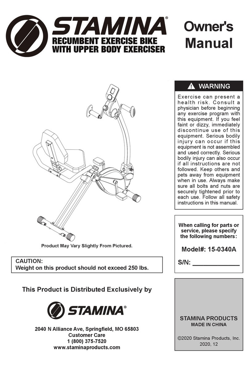
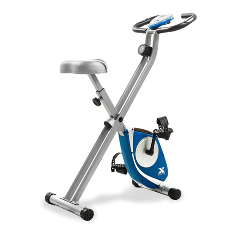
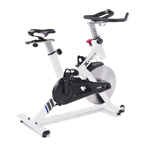
Xterra UB120 User manual

Model: 16204061200
UB120 UPRIGHT BIKE
OWNER’S MANUAL
PLEASE CAREFULLY READ THIS ENTIRE MANUAL BEFORE OPERATING YOUR NEW BIKE

customerservice@dyaco.caDyacoCanadaInc2020
2
TABLE OF
CONTENTS
Before You Begin ...................................................................................3
Important Safety Instructions......................................................................4
UB120 Per-assembly Check List .............................................................6
UB120 Assembly Pack Check List ............................................................7
UB120 Assembly Instructions......................................................................8
Operation of Your New Fitness Bike .........................................................12
User Direction...........................................................................................13
General Maintenance ...............................................................................13
Exploded View Diagram..........................................................................16
Parts List .................................................................................................17
Troubleshooting ......................................................................................18
Manufacturer’s Limited Warranty ............................................................25
ATTENTION
THIS FITNESS BIKE IS INTENDED FOR RESIDENTIAL USE ONLY AND IS WARRANTED FOR THE
APPLICATION. ANY OTHER APPLICATION VOIDS THIS WARRANTY IN ITS ENTIRETY.

customerservice@dyaco.caDyacoCanadaInc2020
3
BEFORE YOU BEGIN
Thank you for choosing the Xterra UB120 Fitness Bike. We take great pride in producing this
quality product and hope it will provide many hours of quality exercise to make you feel better,
look better, and enjoy life to its fullest. It's a proven fact that a regular exercise program can
improve your physical and mental health. Too often, our busy lifestyles limit our time and
opportunity to exercise. The Xterra UB120 Fitness Bike provides a convenient and simple
method to begin your assault on getting your body in shape and achieving a happier and
healthier lifestyle. Before reading further, please review the drawing below and familiarize
yourself with the parts that are labeled.
Read this manual carefully before using the Xterra UB120 Fitness Bike. Although Dyaco
Canada Inc. constructs its products with the finest materials and uses the highest standards of
manufacturing and quality control, there can sometimes be missing parts or incorrectly sized
parts. If you have any questions or problems with the parts included with your Xterra UB120
Fitness Bike, please do not return the product. Contact us FIRST! If a part is missing or
defective call us toll free at 1-888-707-1880. Our Customer Service Staff are available to assist
you from 8:30 A.M. to 5:00 P.M. (Eastern Time) Monday through Friday. Be sure to have the
name and model number of the product available when you contact us.
Handlebar
Hand pulse sensor
Seat
Seat post
Pedal
Rear stabilizer
Computer
Front post
Chain cover
Front stabilizer

customerservice@dyaco.caDyacoCanadaInc2020
4
IMPORTANT SAFETY
INSTRUCTIONS
WARNING - Read all instructions before using this equipment.
Do not operate fitness bike on deeply padded, plush or shag carpet. Damage to both carpet
and fitness bike may result.
Before beginning this or any exercise program, consult a physician. This is especially
important for persons over the age of 35 or persons with pre-existing health conditions.
Keep children under the age of 13 away from this machine. There are obvious pinch points
and other caution areas that can cause harm.
Keep hands away from all moving parts.
Never operate the fitness bike if it has a damaged cord or plug. If the fitness bike is not
working properly, call our customer service.
Never drop or insert any object into any openings.
Do not use outdoors.
The hand pulse sensors are not medical devices. Various factors, including the user’s
movement, may affect the accuracy of heart rate readings. The pulse sensors are intended
only as exercise aids in determining heart rate trends in general.
Wear proper shoes. High heels, dress shoes, sandals or bare feet are not suitable for use
on your fitness bike. Quality athletic shoes are recommended to avoid leg fatigue or injury.
This equipment is not intended for use by persons with reduced physical, sensory or
mental capabilities, or lack of experience and knowledge, unless they have been given
supervision or instruction concerning use of the equipment by a person responsible for
their safety.
User weight should not exceed: 250 lbs (110 kgs)
SAVE THESE INSTRUCTIONS - THINK SAFETY!
CAUTION!! Please be careful when unpacking the carton.
customerservice@dyaco.caDyacoCanadaInc2020
5
WARNING DECAL REPLACEMENT
The decal shown below has been placed on the bike. If the decal is missing or illegible, please
call our Customer Service Department toll‐free at 1‐888‐707‐1880 to order a replacement
decal. Apply the decal in the location shown.

customerservice@dyaco.caDyacoCanadaInc2020
6
UB120
PRE-ASSEMBLY CHECK LIST
Part No. Description Q'ty
1 Main frame 1
2 Front post 1
3 Seat post 1
4 Handleba
r
1
5 Front stabilize
r
1
6 Rear stabilize
r
1
14 Seat 1
18 Compute
r
1
23/24 Left/Ri
g
ht pedal 1/1
Hardware Ba
g
1
Manual 1

customerservice@dyaco.caDyacoCanadaInc2020
7
UB120
ASSEMBLY PACK CHECKLIST
Part No. Description Q'ty
9 Carriage bolt M8x60L 4
10 Allen screw M8x30L 2
19 Curved washer φ8.5xφ20 4
21 Spring washer M8 2
22 domed nut M8 4
25 cover for handlebar 1
26 club knob M12 1
54 Allen Key 1
55 Box Wrench 1
Note: Above parts are all the parts needed to assemble this machine. Before you start to
assemble, please check the hardware packing to make sure they are included.

customerservice@dyaco.caDyacoCanadaInc2020
8
UB120
ASSEMBLY INSTRUCTIONS
1 FRONT AND REAR STABILIZER
1. Attach front stabilizer (5) to main frame (1), tighten with 2sets of Carriage bolt (9), Curved
washer (19) and Domed nut (22).
2. Attach rear stabilizer (6) to main frame (1), tighten with 2sets of Carriage bolt (9), Curved
washer (19) and Domed nut (22).
2 FRONT POST
1. Turn tension knob (20) to level 8, and then
connect it with the lower tension cable (13).
Please see page 9 for a detailed description of
the assembly.
2. Connect extension sensor wire (7) with sensor
wire (12).
3. Insert front post (2) into main frame (1) and
tighten with 4 sets of allen screw (11) and curved
washer (19) which are pre-assembled on the
main frame (1).
4 Carriage Bolt (#9)
4 Curved washer (#19)
4 Domed nut (#22)
Hardware Step 1
Hardware Step 2
Allen key(#54)

customerservice@dyaco.caDyacoCanadaInc2020
9
HOW TO CONNECT THE TENSION CONNECTOR
NOTE: If you are not able to hold the Front Post while connecting the cables and wires,
extra help may be needed.
Pull the Upper Tension
Connector backward and
slide the wire through the slot
on the bracket.
Drop down the Connector so
the fitting sits firmly on top of
the bracket.
Slide the Cable wire from the
Upper Tension Connector in
between the opening on the
wire holder on the Lower
Tension Connector.

customerservice@dyaco.caDyacoCanadaInc2020
10
3 SEAT ASSEMBLY
1. Attach seat (14) to the seat post (3). Securing with
three sets of flat washers (15), and nylon nut (17) which
are pre-assembled on the seat (14).
2. Insert the seat post (3) into main frame (1) and tighten
with the club knob (26).
4 PEDAL ASSEMBLY
1. The left and right pedals (23 & 24) are marked “L” & “R”.
Attach the straps to the pedals. Connect left pedal (23) to the
crank (8) on the left-hand side of the cycle as you sit on it.
Repeat for the right pedal (24).
Note that the right pedal should be threaded on
clockwise and the left pedal on counterclockwise.
Hardware Step 3
Hardware Step 4
Box wrench(#55)
Club knob(#26)
Box wrench(#55)

customerservice@dyaco.caDyacoCanadaInc2020
11
5 HANDLEBAR ASSEMBLY
1. Attach handlebar (4) to the front post (2) and secure
with two sets of Allen screws (10) and Spring
washer (21).
6 COMPUTER ASSEMBLY
1. Remove the Grommet (28) from the Front
Post (2).
2. Insert hand pulse wires (27) into grommet (28)
and pull out from the top bracket. Connect hand
pulse wires (27) and extension sensor wire (7)
to computer (18).
3. Attach computer (18) to the top bracket of front
post (2). Securing with two screws (16) which are
pre-assembled on the computer (18).
Install the cover for the handlebar (25) over the
Handlebar.
Hardware Step 5
Allen Key (#54)
2 Allen screw (#10)
2 Spring washer (#21)
Hardware Step 6
Allen Key (#54)
Cover for handlebar (#25)

customerservice@dyaco.ca
DyacoCanadaInc2020
12
OPERATION OF YOUR FITNESS BIKE
GETTING FAMILIAR WITH THE CONTROL PANEL
UB120 CONSOLE
Key Functions
MODE: Press to select functions. Press the button and hold for two seconds to reset all
functions to zero, except ODOMETER.
Functions
Scan: Press MODE button until “▼” appears at SCAN position, the console displays: time, speed, distance,
calories, odometer and pulse, in sequence for 6 seconds at a time.
Time: Display the time from exercise start to the end
Speed: Display the current speed.
Distance: Display the distance from exercise start to the end.
Calories: Display the calories burned from the exercise start to the end.
The calorie readout is an estimate for an average user. It should be used only as comparison
between workouts on this unit.
ODO: Display the total accumulated distance you have travelled. The odometer does not reset unless you
remove the batteries.
Pulse: Display an average current heartbeat rate in beats per minute (BPM). To use this feature, place hands
on the pulse grips and hold for 6 ~ 7 seconds to get a more accurate reading. Please note that due to
contact delay, the heart rate will be higher than the actual heart rate during the first 2 ~ 3 seconds of
measurement, then will return to normal level. The measurement value shouldn’t be regarded as the
basis of medical treatment.
Getting Familiar with the Control Panel
FUNCTION
AUTO SCAN Every 6 seconds
TIME 0:00’~99:59’
SPEED 0.0~999.9 KM/H(MILE/H)
DISTANCE 0.00~999.9 KM(MILE)
CALORIES 0.0~999.9 CAL
ODOMETER 0.0~9999 KM(MILE)
PULSE 40~240 BPM
BATTERY TYPE 2 AAA or UM 4
OPERATING TEMPERATURE 0°C ~ +40°C, 32˚F ~ 104˚F
STORAGE TEMPERATURE -10°C ~ +60°C, 14˚F ~ 140˚F
(1) The console turns on when you start pedaling or when you press a key.
(2)The console turns off automatically after 4 minutes of inactivity.

customerservice@dyaco.caDyacoCanadaInc2020
13
USER DIRECTION
HOW TO ADJUST THE SEAT
The correct height for the seat can be adjusted by the
club knob.You need to unscrew the club knob and
lift or lower the seat height at your desired position,
and then tighten the club knob.
HOW TO ADJUST THE PEDAL STRAPS
To adjust the pedal straps, first pull the
ends of the straps off the tabs on the pedals.
Adjust the straps to the desired position, and
then press the ends of the straps onto the
tabs.
HOW TO MOVE THE BIKE
The bike has a pair of Transportation wheels
on the Front Stabilizer. To move, carefully hold
and tilt the handle toward to front and then roll.
GENERAL MAINTENANCE
The safety of this product can be maintained only if regular periodic checks are made. Most
checks can be performed once a week. However, some checks should be made before each
workout, and are indicated as such below.
Checks
• Check that seat nuts are secure, check before each workout.
• Check that pedals are tight; pedals can work loose over time.
• Check that stabilizer bolts are tight, check before each workout.
• Check that handlebar is secure, if not, tighten, check before each workout.
• Should a part become defective, replace it immediately. Do not allow use of the equipment
until it has been repaired.
Cleaning
A damp cloth is sufficient to clean most surfaces of this unit. Be careful not to drip water on the
monitor. A mild liquid soap may be added if needed.

customerservice@dyaco.caDyacoCanadaInc2020
14
HOW TO ADJUST THE REED SWITCH OR SENSOR WIRE
If the console does not display correct feedback, the reed switch should be adjusted. To adjust the reed switch,
the chain cover (29&51) must first be removed.
Remove the left pedal (23) from the crank (8).
Remove the crank cover (30) from the chain cover (29&51).
Remove the two Cross head self-tapping screws (44) from each side of chain cover (29&51). Remove another
six ST4.2x20L self-tapping screws (40) from left chain cover (51).
Hold the chain cover (29&51) near the back and pull it apart slightly until the chain cover can be lifted off the
ends of the crank (8). Do not pull the chain cover apart at the top or the seam may be broken.
Next, locate the sensor wire (12). Turn the pulley until the magnet is aligned with the reed switch. Loosen, but
do not remove, the ST3.2x12L screw (39). Slide the reed switch slightly toward or away from the magnet.
Make sure that the magnet will not hit the reed switch. Retighten the screw (39). Turn the pulley for a moment.
Repeat until the console displays correct feedback. When the Reed Switch is correctly adjusted, reattach the
Chain Cover and the Crank Covers.

customerservice@dyaco.caDyacoCanadaInc2020
15
HOW TO ADJUST THE DRIVE BELT
If you can feel the pedals slip while you are pedaling, even when the resistance is adjusted to the
highest level, the drive belt may need to be adjusted. To adjust the drive belt, the Chain Cover
(29&51) must first be removed.
Loosen two france nut (A) and adjustor (B).
Turned to screws(C)of adjustor at clockwise or counterclockwise at same time to make belt have suitable
tension, also ensure two adjuster have same distance to axis.
Tighten two france nut (A) and adjuster(B).
B
C
C
B

customerservice@dyaco.caDyacoCanadaInc2020
16
EXPLODED VIEW DIAGRAM

customerservice@dyaco.caDyacoCanadaInc2020
17
PARTS LIST
Key Part Number DESCRIPTION QTY
01 0612001 Main frame 1
02 0612002 Front pos
t
1
03 0612003 Seat pos
t
1
04 0612004 Handlebar 1
05 0612005 Front stabilizer 1
06 0612006 Rear stabilizer 1
07 0612007 Extension sensor wire 1
08 0612008 Crank w/pulle
y
1
09 0612009 Carria
g
e bolt M8x60L 4
10 0612010
A
llen screw M8x30L 2
11 0612011
A
llen screw M8x15L 4
12 0612012 Sensor wire 1
13 0612013 Lower tension cable 1
14 0612014 Seat cushion KX6614 1
15 0612015 Flat washer φ8.5xφ20 3
16 0612016 Screw M5x10L 2
17 0612017 N
y
lon nut M8 3
18 0612018 Computer 1
19 0612019 Curved washer φ8.5xφ20 8
20 0612020 Tension knob w/ upper tension cable 1
21 0612021 Sprin
g
washer M8 2
22 0612022 Domed nut M8 4
23 0612023 Left pedal 1
24 0612024 Ri
g
ht pedal 1
25 0612025 Cover for handlebar 1
26 0612026 Club knob M12 1
27 0612027 Pulse wire 2
28 0612028 Gromme
t
2
29 0612029 Ri
g
ht chain cover 1
30 0612030 Crank cover 2
31 0612031 End cap for handlebar 2
32 0612032
A
d
j
ustment bolt 1 1
33 0612033 Bushin
g
for seat pos
t
1
34 0612034 End cap for rear stabilizer 2
35 0612035 End cap for front stabilizer 2
36 0612036 Fl
y
wheel w/ ma
g
net assembl
y
1
37 0612037 Self-tappin
g
screw ST4.2x12L 2
38 0612038 Curved washer φ5.5xφ20 1
39 0612039 Self-tappin
g
screw ST3.2x12L 1
40 0612040 Self-tappin
g
screw ST4.2x20L 8
41 0612041 Foam
g
rip for handlebar 2
42 0612042 Belt 1
43 0612043 EVA pad 1
44 0612044 Cross head self-tappin
g
screw ST4.2x20L 4
45 0612045 Screw M5x40L 1
46 0612046 Flat washer φ12.5xφ20x1.5t 1
47 0612047 F0lan
g
e nut M10 2
48 0612048 Bearin
g
assembl
y
1
49 0612049
A
djustment bolt 2 2
50 0612050 Sensor bracket 1
51 0612051 Left chain cover 1
52 0612052 Flat washer φ4.3xφ12 2
53 0612053 Hand pulse sensor 2
54 0612054
A
llen ke
y
1
55 0612055 Box wrench 1

customerservice@dyaco.caDyacoCanadaInc2020
18
TROUBLESHOOTING
Problem Cause Solution
Monitor does not display
Adapter not plugged in Plug adapter in
Computer Wires not connected
Ensure the computer wires are
connected properly at the upright
and computer
No speed or distance displays
on the monitor
Sensor wire not connected
Ensure the computer wires are
connected properly at the upright
and the computer
Sensor wire not working properly Replace sensor wire
Monitor not working properly Replace monitor
No tension
Magnetic wheel not working properly Replace magnetic wheel
Computer wires not connected
properly
Ensure the computer wires are
connected
properly at the upright and
the computer
Heart rate not displaying
Pulse wire not connected Secure plug wires together
Hand pulse defective Replace hand pulse grip
Monitor not working Replace Monitor
Grinding Noise
Crank bearing defective Replace crank bearings
Idler pulley defective Replace idler pulley
Flywheel defective Replace flywheel
Squealing V-belt slipping Adjust v-belt

customerservice@dyaco.caDyacoCanadaInc2020
19
TRAINING
GUIDELINES
EXERCISE
Exercise is one of the most important factors in the overall health of an individual. Listed among
its benefits are:
Increased capacity for physical work (strength endurance)
Increased cardiovascular (heart and arteries/veins) and respiratory efficiency
Decreased risk of coronary heart disease
Changes in body metabolism, e.g. losing weight
Delaying the physiological effects of age
Physiological effects, e.g. reduction in stress, increase in self-confidence, etc.
BASIC COMPONENTS OF PHYSICAL FITNESS
There are four all-encompassing components of physical fitness and we need to briefly define
each and clarify its role.
Strength is the capacity of a muscle to exert a force against resistance. Strength
contributes to power and speed and is of great importance to a majority of sports people.
Muscular Endurance is the capacity to exert a force repeatedly over a period of time, e.g. it
is the capacity of your legs to carry you 10 Km without stopping.
Flexibility is the range of motion about a joint. Improving flexibility involves the stretching of
muscles and tendons to maintain or increase suppleness, and provides increased
resistance to muscle injury or soreness.
Cardio-Respiratory Endurance is the most essential component of physical fitness. It is the
efficient functioning of the heart and lungs
AEROBIC FITNESS
The largest amount of oxygen that you can use per minute during exercise is called your
maximum oxygen uptake (MVo2). This is often referred to as your aerobic capacity.
The effort that you can exert over a prolonged period of time is limited by your ability to deliver
oxygen to the working muscles. Regular vigorous exercise produces a training effect that can
increase your aerobic capacity by as much as 20 to 30%. An increased MVO2 indicates an
increased ability of the heart to pump blood, of the lungs to ventilate oxygen and of the muscles
to take up oxygen.
Anaerobic Training
This means “without oxygen” and is the output of energy when the oxygen supply is insufficient
to meet the body’s long term energy demands. (For example, 100 meter sprint).
The Training Threshold
This is the minimum level of exercise which is required to produce significant
improvements in any physical fitness parameter.

customerservice@dyaco.caDyacoCanadaInc2020
20
Progression
As your become fitter, a higher intensity of exercise is required to create an overload and
therefore provide continued improvement
Overload
This is where you exercise at a level above that which can be carried out comfortably. The
intensity, duration and frequency of exercise should be above the training threshold and should
be gradually increased as the body adapts to the increasing demands. As your fitness level
improves, so the training threshold should be raised.
Working through your program and gradually increasing the overload factor is important.
Specificity
Different forms of exercise produce different results. The type of exercise that is carried out is
specific both to the muscle groups being used and to the energy source involved.
There is little transfer of the effects of exercise, i.e. from strength training to cardiovascular
fitness. That is why it is important to have an exercise program tailored to your specific needs.
Reversibility
If you stop exercising or do not do your program often enough, you will lose the benefits you
have gained. Regular workouts are the key to success.
WARM UP
Every exercise program should start with a warm up where the body is prepared for the effort to
come. It should be gentle and preferably use the muscles to be involved later.
Stretching should be included in both your warm up and cool down, and should be performed
after 3-5 minutes of low intensity aerobic activity or callisthenic type exercise.
Warm Down or Cool Down
This involves a gradual decrease in the intensity of the exercise session. Following exercise, a
large supply of blood remains in the working muscles. If it is not returned promptly o the central
circulation, pooling of blood may occur in the muscles
Heart Rate
As you exercise, so the rate at which your heart beat also increases. This is often used as a
measure of the required intensity of exercise. You need to exercise hard enough to condition
your circulatory system, and increase your pulse rate, but not enough to strain your heart.
Your initial level of fitness is important in developing an exercise program for you. If you are
starting off, you can get a good training effect with a heart rate of 110-120 beats per minute
(BPM). If you are fitter, you will need a higher threshold of stimulation.
To begin with, you should exercise at a level that elevates your heart rate to about 65 to 70% of
your maximum. If you find this is too easy, you may want to increase it, but it is better to lean on
the conservative side.
As a rule of thumb, the maximum heart rate is 220 minus your age. As you increase in age, so
your heart, like other muscles, loses some of its efficiency. Some of its natural loss is won back
as fitness improves.
Other manuals for UB120
1
This manual suits for next models
1
Table of contents
Other Xterra Exercise Bike manuals

Xterra
Xterra MBX2500 User manual

Xterra
Xterra XB 78 User manual

Xterra
Xterra UB1.7 User manual

Xterra
Xterra AIR350 User manual

Xterra
Xterra 16416880-1 User manual

Xterra
Xterra SB120 User manual

Xterra
Xterra UB2.5 User manual

Xterra
Xterra UP150 User manual

Xterra
Xterra SB440r User manual

Xterra
Xterra FB360 User manual

Xterra
Xterra 16468451US User manual

Xterra
Xterra 16416852 User manual

Xterra
Xterra MB880 User manual

Xterra
Xterra UB1.5 User manual

Xterra
Xterra FB160 User manual

Xterra
Xterra SB500 User manual

Xterra
Xterra MB500 User manual

Xterra
Xterra MB8.5 User manual

Xterra
Xterra SB4.5r User manual

Xterra
Xterra MB550 User manual