of effort w s put into the crossover filter. All
p ssive components re the highest qu lity to
minimize the influence on the sign l. The
crossover is pl ced in sep r te enclosure.
We use n optim l selection of ir wound coils
(with low intern l resist nce) nd coils with steel
cores (these ccept high level of m gnetic
s tur tion), MKP c p citors nd MOX resistors.
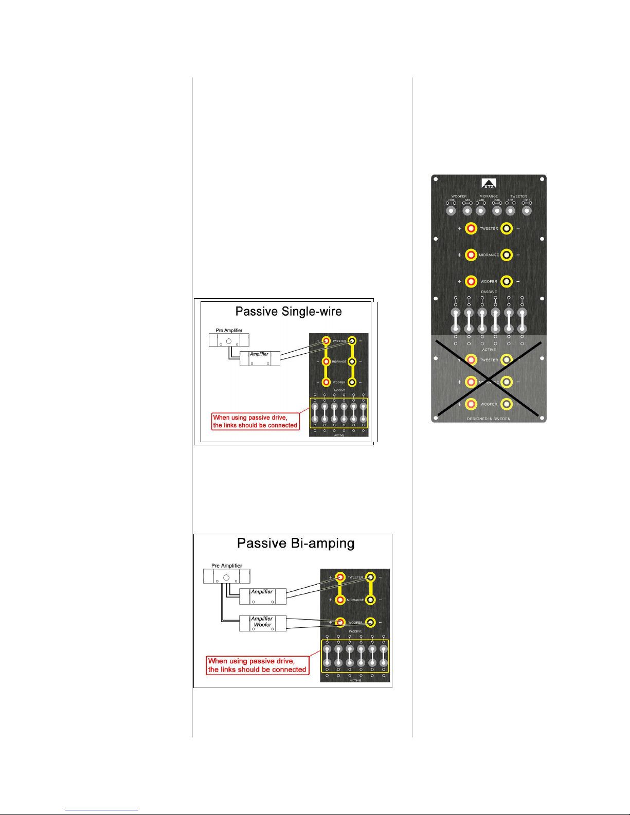
The termin l is divided into two input re s. One
for p ssive (norm l) nd one for ctive drive. All
termin l screws nd inputs re gold pl ted.
The ctive inputs h ve direct connection with the
drivers. The thought behind this is th t the spe ker
c n be used fully ctively in the future to get the
most out of the system.
When using the byp ss jumpers in the middle of
the termin l, the spe ker is in “p ssive mode” nd
connected to the p ssive cross over
It is possible to drive the woofers ctively nd g in
the possibility to use DSP b sed room correction.
There re three links/jumpers th t c n be used to
lter the ch r cter of the spe ker.
One link/jumper for the tweeter (0 or +3dB)
One link/jumper for the midr nge (0 or -2dB)
One link/jumper for the woofers (0 or +3dB)