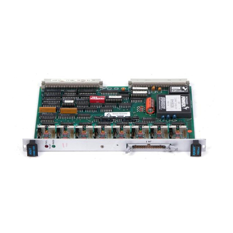
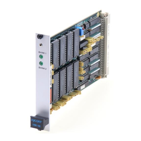
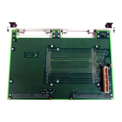
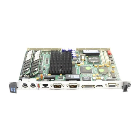
Xycom XVME-976 User manual

XVME-976
Adapter Module
P/N 74976-001A
© 1996 XYCOM, INC. XYCOM
750 North Maple Road
Printed in the United States of America Saline, Michigan 48176-1292
Part Number 74976-001A (313) 429-4971

Xycom Revision Record
Revision Description Date
A Manual Released 10/96
Trademark Information
Brand or product names are registered trademarks of their respective owners.
Windows is a registered trademark of Microsoft Corp. in the United States and other countries.
Copyright Information
This document is copyrighted by Xycom Incorporated (Xycom) and shall not be reproduced or copied
without expressed written authorization from Xycom.
The information contained within this document is subject to change without notice. Xycom does not
guarantee the accuracy of the information and makes no commitment to keeping it up to date.
Address comments concerning this
manual to:
xycom
Technical Publications Department
750 North Maple Road
Saline, MI 48176-1292
Part Number 74976-001A

i
Table of Contents
Chapter 1 −
− −
− Introduction
Overview................................................................................................................................................................ 1-1
Module Features .................................................................................................................................................... 1-1
Expansion Modules................................................................................................................................................ 1-1
PC/104 Expansion Modules................................................................................................................................ 1-2
PCI Mezzanine Card (PMC) Expansion Modules .............................................................................................. 1-2
Processor Connection Options............................................................................................................................... 1-2
Installing the XVME-976 on an XVME-654...................................................................................................... 1-2
Installing the XVME-976 on an XVME-655...................................................................................................... 1-4
PC/104 Module Installation................................................................................................................................... 1-6
Type A Module Installation ................................................................................................................................ 1-7
Type B Module Installation ................................................................................................................................ 1-8
PMC Module Installation..................................................................................................................................... 1-11
Connectors ........................................................................................................................................................... 1-13
PC/104 Connector Pinouts................................................................................................................................ 1-13
PMC Expansion Site Connector Pinouts........................................................................................................... 1-14
VME-P1............................................................................................................................................................ 1-17
80pin Interboard Connector 1 Pinout (P5)........................................................................................................ 1-17
80-pin Interboard Connector 2 Pinout (P6)....................................................................................................... 1-19
Environmental Specifications .............................................................................................................................. 1-20
Hardware Specifications ...................................................................................................................................... 1-20
Chapter 2 −
− −
− SSP Installation
Introduction ........................................................................................................................................................... 2-1
Serial Port Driver/Receivers .................................................................................................................................. 2-2
Jumper Settings...................................................................................................................................................... 2-3
Base I/O Address Selection ................................................................................................................................... 2-3
Interrupt Selection............................................................................................................................................... 2-5
Serial Port Configuration and Connection ............................................................................................................. 2-6
RS-232C Usage - COM A and COM B .............................................................................................................. 2-7
RS-485 Usage - J2 Full Duplex .......................................................................................................................... 2-7
RS-485 Usage - J2 Half Duplex.......................................................................................................................... 2-8
Parallel Port Configuration and Connection .......................................................................................................... 2-9
Specifications....................................................................................................................................................... 2-10
Chapter 3 −
− −
− SCSI Installation

XVME-976 Adapter Module
ii
Introduction ........................................................................................................................................................... 3-1
Driver Operation.................................................................................................................................................... 3-2
Utility Programs.................................................................................................................................................. 3-2
Driver Installation ............................................................................................................................................... 3-2
ASPI2DOS.SYS Options.................................................................................................................................... 3-3
Aspidisk.Sys .......................................................................................................................................................... 3-4
Switch Settings....................................................................................................................................................... 3-4
Partitioning and Formatting ................................................................................................................................ 3-6
AFDISK Operation ............................................................................................................................................. 3-6
BIOS Operation ..................................................................................................................................................... 3-7
Module Switch Configuration............................................................................................................................. 3-7
Booting from a SCSI Drive and Installing Drivers on that Device ..................................................................... 3-10
Cable Installation ................................................................................................................................................. 3-10
Connector Definition ........................................................................................................................................... 3-11
Specifications....................................................................................................................................................... 3-11
Chapter 4 −
− −
− Memory Expansion Module Installation
Memory Expansion Module Installation................................................................................................................ 4-1
Jumper Configuration Summary ............................................................................................................................ 4-1
General Module Setup ........................................................................................................................................... 4-3
Window Address Selection ................................................................................................................................. 4-3
Control Register Port Address ............................................................................................................................ 4-4
Board Number (W11) ......................................................................................................................................... 4-4
Power Fail Interrupt Jumpers (W10, W5)........................................................................................................... 4-5
Memory Device Configuration (W1-4, W6-9) ...................................................................................................... 4-6
Installing 28-Pin Devices in 32-Pin Sockets ....................................................................................................... 4-8
Static RAM Jumpering........................................................................................................................................ 4-8
EPROM Jumpering........................................................................................................................................... 4-10
Jumper Array Summary ....................................................................................................................................... 4-13
Battery Backup Configuration And Battery Information..................................................................................... 4-14
Safety Information ............................................................................................................................................ 4-14
Battery Connection ........................................................................................................................................... 4-15
Installation to Carrier Card .................................................................................................................................. 4-16
XVME-976 Installation .................................................................................................................................... 4-16
Programming ....................................................................................................................................................... 4-18
Control Register Usage........................................................................................................................................ 4-18
Control Register 1 Functions ............................................................................................................................ 4-18
Control Register 2 Functions ............................................................................................................................ 4-20
Reading the Registers........................................................................................................................................ 4-21
Selecting Portions of Large Devices.................................................................................................................... 4-22
Board Number ..................................................................................................................................................... 4-23
Window Address Selection.................................................................................................................................. 4-23

Table of Contents
iii
Chapter 5 −
− −
− 16-Bit Ethernet Installation
Introduction ........................................................................................................................................................... 5-1
Hardware Configuration ........................................................................................................................................ 5-1
Jumper Settings................................................................................................................................................... 5-2
Installation .......................................................................................................................................................... 5-3
Software Configuration.......................................................................................................................................... 5-4
SET4I29.............................................................................................................................................................. 5-4
SHOW4I29 ......................................................................................................................................................... 5-9
Default Configuration ......................................................................................................................................... 5-9
Interface Connectors ............................................................................................................................................ 5-10
10BASE2 .......................................................................................................................................................... 5-10
10BASET.......................................................................................................................................................... 5-10
AUI ................................................................................................................................................................... 5-10
Specifications....................................................................................................................................................... 5-11

Chapter 1 – Introduction
1-1
Chapter 1 - Introduction
Overview
The XVME-976 adapter module provides I/O expansion for Xycom’s
XVME-654 and XVME-655 VMEbus PC/AT processor modules. Direct
connection is possible with the XVME-654. Connections with the XVME-
655 require a transition board, such as the XVME-978/1 Ethernet card, or
XVME-978/100 transition module, which plug into the XVME-655 and pro-
vide the mechanical and electrical connections for the XVME-976.
Module Features
The XVME-976 offers the following features:
•One PC/104 and one PMC expansion module site
•On-board DC regulator to supply 3.3 volts to the PMC site
•Pin and socket connector scheme
•Optional PC/104-compatible modules for Ethernet, SCSI, serial and par-
allel expansion (available from Xycom)
•Optional PMC modules (available through third party) for ATM, FDDI
and SCSI expansion
Expansion Modules
Minimal configuration for an expanded system includes:
•VMEbus processor module (the XVME-654 or XVME-655 with
XVME-978/1 or 978/100)
•XVME-976 adapter module
•PC/104 or PMC expansion module

XVME-976 Adapter Module
1-2
PC/104 Expansion Modules
The PC/104 expansion site on the XVME-976 allows PC/104 compatible
modules to be used with XVME-654/655. These signals arrive from the host
XVME-PC/AT. PC/104 expansion modules provide various I/O functions
such as: Ethernet, SCSI, serial, parallel and flash disk.
Two types of PC/104 expansion modules can be used with the XVME-976
adapter module:
•Type A – Xycom PC/104 module with integral front panel included; me-
chanical dimensions of 4.010” x 5.091”
•Type B – Generic PC/104 module; mechanical dimensions of 3.550” x
3.775” (may require additional front panel kit)
PCI Mezzanine Card (PMC) Expansion Modules
The XVME-976 provides a PCI Mezzanine Card (PMC) site that allows the
PCI functionality of the XVME-654 and -655 to be expanded. Electrically
equivalent to the PCI bus standard, PMC has been adopted by VMEbus In-
ternational Trade Association (VITA) and the VMEbus community to ex-
pand the PCI capability of the VMEbus processor modules. The PMC site on
the XVME-976 supports PMC J2 I/O options.
Processor Connection Options
The XVME-976 supports connections to the XVME-654 and XVME-655
VMEbus PC/AT processor modules.
Installing the XVME-976 on an XVME-654
The adapter module connects directly to the XVME-654 via Interboard Con-
nectors 1 and 2. Additional equipment (supplied with the XVME-976)
needed to complete the connection is as follows:
•Two corner standoffs
•Two pairs of standoff screws
Installing the XVME-976 to the host XVME-654 Processor
Module
1. Follow procedures for the prevention of static discharge to prevent dam-
age to the circuitry of the modules.
2. Disconnect all power sources.
3. Loosen the screws on the front panel of the XVME-654 processor mod-
ule.
4. Remove the XVME-654 from the VME backplane, as follows:
•Gently pull on the face plate until it slides out of the chassis

Chapter 1 – Introduction
1-3
5. Place the XVME-654 on a static-free surface with the Interboard con-
nectors facing up.
6. Align interboard connectors 1 and 2 on the XVME-976 with the same
connectors on the XVME-654.
7. Gently press the two boards together. Do not bend or twist the XVME-
976.
8. Add standoffs (2) and standoff screws (2 pairs) as illustrated in Figure 1-
1.
Figure 1-1. Installing XVME-976 onto XVME-654
9. Clear two adjacent card cage slots.
10. Align the two connected modules (with the XVME-976 on the right) on
the card guides in the slots.
11. Gently push the modules to the rear of the chassis until the P1 and P2
connectors engage.
12. Tighten the screws on the front panel of the XVME-654 processor mod-
ule to secure the connected modules into place. The installation is com-
plete.

XVME-976 Adapter Module
1-4
Installing the XVME-976 on an XVME-655
The XVME-976 connects to the XVME-655 indirectly through an XVME-
978 expansion module. Additional equipment needed to complete the con-
nection is as follows:
•Two long standoffs, and either the
•XVME-978/1 Ethernet expansion module or the
•XVME-978/100 transition module (if Ethernet functionality is not
needed)
Installing the XVME-976 to the Host XVME-655 Processor
Module
Note
This procedure assumes the XVME-978 has been installed onto
the XVME-655 processor module. Instructions for installing the
XVME-978 onto the XVME-655 can be found in the XVME-
655 manual.
1. Follow procedures for the prevention of static discharge to prevent dam-
age to the circuitry of the modules.
2. Disconnect all power sources.
3. Loosen the screws on the front panel of the XVME-655 processor mod-
ule.
4. Remove the XVME-655 (with XVME-978 connected) from the VME
backplane, as follows:
•Gently pull on the face plate until it slides out of the chassis
5. Place the boards on a static-free surface with the XVME-978 on top.
6. Align interboard connectors 1 and 2 on the XVME-976 with the inter-
board connectors on the XVME-978 module.
7. Gently press the two boards together. Do not bend or twist the XVME-
976.
8. Add standoffs (2) and standoff screws (2 pairs) as illustrated in Figure 1-
2.

Chapter 1 – Introduction
1-5
Figure 1-2. Installing XVME-976 onto XVME-978
9. Clear three adjacent card cage Slots.
10. Align the three connected modules (with the XVME-976 on the right) on
the plastic guides in the slots.
11. Gently push the modules to the rear of the chassis until the P1 and P2
connectors engage.
12. Tighten the screws on the front panel of the XVME-655 processor module to
secure the connected modules into place. The installation is complete.

XVME-976 Adapter Module
1-6
PC/104 Module Installation
The following types of PC/104 expansion modules can be mounted to the
XVME-976:
•Xycom’s Type A (PC/104) expansion modules
•Generic Type B (PC/104) expansion modules
•PMC expansion modules
The following sections explain the installation procedures for mounting
PC/104-compatible (Types A and B) expansion modules onto an XVME-976
adapter module.
Figure 1-3. XVME-976 with PMC and Type A (4.010 x 5.091") Modules

Chapter 1 – Introduction
1-7
Type A Module Installation
The XVME-976 is configured to accept the installation of Xycom’s Type A
module in the PC/104 site. Type A modules contain a front panel that is at-
tached to the circuit board. Additional equipment included for the connec-
tion of the two modules:
•Six standoffs
•Eight nylon screws (connects the corners of the module to the XVME-976)
Installing the Type A Module onto the XVME-976 Adapter
Module
Note
This procedure assumes the XVME-976 is attached to either the
XVME-654 or XVME-655 module. Procedures for installing
the XVME-976 onto those modules can be found earlier in this
chapter.
1. Follow procedures for the prevention of static discharge to prevent dam-
age to the circuitry of the modules.
2. Disconnect all power sources.
3. Loosen the screws on the front panel of the XVME processor module.
4. Remove the XVME-976 and any attached modules from the VME back-
plane, as follows:
•Gently pull on the face plate(s) until the board(s) slide out of the
chassis
5. Place the XVME-976 (and any attached boards) on a static-free surface
with the XVME-976 on top. See Figure 1-3.
6. Remove four screws securing the blank front panel assembly from the
XVME-976 (set aside for later).
7. Remove the blank front panel assembly from XVME-976 (save for pos-
sible future use).
8. Remove the four screws securing the mylar shield. Be sure to retain the
screws for use in securing the PC/104 module to the XVME-976.
9. Remove the mylar shield from the XVME-976 PC/104 site (save for fu-
ture use).
10. Install the new mylar shield that came with the Type A expansion board.
11. Insert two screws on the standoffs, adjacent to the PC/104 connector, to
secure the mylar shield.
12. Fold the mylar shield up to allow expansion module installation.

XVME-976 Adapter Module
1-8
13. Align the PC/104 connectors of the XVME-976 with the corresponding
connectors on the Type A module.
14. Gently press the two boards together. Do not bend or twist the XVME-
976.
15. Fold the mylar shield down.
16. Install the remaining screws to secure the Type A module.
17. Align the three connected modules (with the Type A module on the
right) on the plastic guides in the slots leading to the VME backplane.
18. Gently push the modules to the rear of the chassis until the P1 and P2
connectors engage.
19. Tighten the screws on the front panel of the XVME processor module to
secure the connected modules into place. The installation is complete.
Type B Module Installation
The XVME-976 is configured to accept the installation of generic Type B
modules in the PC/104 site. Type B modules contain cable connectors may
require a Xycom front panel kit. Additional equipment included or required
for connecting a Type B module to the XVME-976:
•Xycom front panel kit
•Six standoffs
•Two nylon screws (secures the module to the XVME-976)
•Four nylon screws (secures the front panel to the XVME-976)
Note
Type B modules purchased from Xycom will include a front
panel kit. PC/104 modules purchased from a third party will not
contain front panel kits compatible with the XVME-976.

Chapter 1 – Introduction
1-9
Installing Type B Module onto the XVME-976 Adapter Mod-
ule
Note
This procedure assumes the XVME-976 is attached to either the
XVME-654 or XVME-655 module. Procedures for installing
the XVME-976 onto those modules can be found earlier in this
chapter.
Figure 1- 4. XVME-976 with Type B (3.550” x 3.775”) and PMC Modules Installed
1. Follow procedures for the prevention of static discharge to prevent dam-
age to the circuitry of the modules.
2. Disconnect all power sources.
3. Loosen the screws on the front panel of the XVME processor module.
4. Remove the XVME-976 and any attached modules from the VME back-
plane, as follows:
•Pull gently on the face plate(s) until the board(s) slide out of the
chassis
5. Place the XVME-976 (and any attached boards) on a static-free surface
with the XVME-976 on top. See Figure 1-3.
6. Remove four screws securing the blank front panel assembly from the
XVME-976 (set aside for later).

XVME-976 Adapter Module
1-10
7. Remove blank front panel assembly from XVME-976 (save for possible
future use).
8. Connect the cables from the front panel kit to the Type B expansion
module.
9. Remove the two screws opposite the PC/104 connector and fold the
mylar shield back to expose the standoffs. Be sure to retain the screws
for use in securing the PC/104 module to the XVME-976.
10. Align the PC/104 connectors of the XVME-976 with the corresponding
connectors on the Type B module.
11. Gently press the two boards together. Do not bend or twist the XVME-
976.
12. Fold the mylar shield down (over the solder side of the expansion mod-
ule).
13. Insert the two screws removed in Step 9.
14. Attach the new front panel assembly, if provided, to the XVME-976
with the four screws removed in Step 6.
15. Align the connected modules (with the XVME-976 on the right) on the
plastic guides in the slots.
16. Gently push the modules to the rear of the chassis until the P1 and P2
connectors engage.
17. Tighten the screws on the front panel of the XVME processor module to
secure the connected modules into place. The installation is complete.

Chapter 1 – Introduction
1-11
PMC Module Installation
The XVME-976 is designed to accept the installation of PMC expansion
modules to add PCI functionality.
Figure 1-5. XVME-976 with PMC Expansion Module
Note
The XVME-976 PMC site is keyed to accept only 5-volt boards.
Other voltage configurations will not fit on this site.

XVME-976 Adapter Module
1-12
Installing the PMC Module onto the XVME-976 Adapter
Module
Note
This procedure assumes the XVME-976 is attached to either the
XVME-654 or XVME-655 module. Procedures for installing
the XVME-976 onto those modules can be found earlier in this
chapter.
1. Follow procedures for the prevention of static discharge to prevent dam-
age to the circuitry of the modules.
2. Disconnect all power sources.
3. Loosen the screws on the front panel of the XVME processor module.
4. Remove the XVME-976 and any attached modules from the VME back-
plane, as follows:
•Gently pull on the face plate(s) until the board(s) slide out of the
chassis
5. Place the XVME-976 (and any attached boards) on a static-free surface
with the XVME-976 on top. See Figure 1-5.
6. Pop out the filler plate in the XVME-976 front panel.
7. Align the PMC board with the 5-volt key. See Figure 1-5.
8. Insert the four screws to secure the expansion module to the XVME-976.
9. Align the connected modules (with the XVME-976 on the right) on the
plastic guides in the slots.
10. Gently push the modules to the rear of the chassis until the P1 and P2
connectors engage.
11. Tighten the screws on the front panel of the XVME processor module to
secure the connected modules into place. The installation is complete.

Chapter 1 – Introduction
1-13
Connectors
The following tables contain pinout information for the various XVME-976
connectors:
PC/104 Connector Pinouts
Table 1-1. PC/104 Connector Pinouts
Pin Row A (P3) Row B (P3) Row D (P4) Row C (P4)
0- - GND GND
1 IOCHCK* GND MEMCS16* SBHE*
2 SD7 RESETDRV IOCS16* LA23
3 SD6 +5V IRQ10 LA22
4 SD5 IRQ9 IRQ11 LA21
5SD4 NC IRQ12LA20
6 SD3 DRQ2 IRQ15 LA19
7 SD2 -12V IRQ14 LA18
8 SD1 NC NC LA17
9 SD0 +12V NC MEMR*
10 IOCHRDY NC DACK5* MEMW*
11 AEN SMEMW* DRQ5 SD8
12 SA19 SMEMR* DACK6* SD9
13 SA18 IOW* DRQ6 SD10
14 SA17 IOR* NC SD11
15 SA16 NC NC SD12
16 SA15 NC +5V SD13
17 SA14 DACK1* NC SD14
18 SA13 DRQ1 GND SD15
19 SA12 REF* GND NC
20 SA11 SYSCLK
21 SA10 IRQ7
22 SA9 IRQ6
23 SA8 IRQ5
24 SA7 IRQ4
25 SA6 IRQ3
26 SA5 DACK2
27 SA4 TC
28 SA3 ALE
29 SA2 +5V
30 SA1 OSC
31 SA0 GND
32 GND GND

XVME-976 Adapter Module
1-14
PMC Expansion Site Connector Pinouts
Table 1-2. J-11 Pinouts
Pin Name Pin Name
1 TCK 2 -12V
3 GND 4 INTA*
5 INTB* 6 INTC*
7 BUSMODE1* 8 +5V
9 INTD* 10 PCI-RSVD14B
11 GND 12 PCI-RSVD
13 CLK 14 GND
15 GND 16 GNT*
17 REQ* 18 +5V
19 V I/O 20 PAD
(
31
)
21 PAD
(
28
)
22 PAD
(
27
)
23 PAD
(
25
)
24 GND
25 GND 26 C BE3*
27 PAD
(
22
)
28 PAD
(
21
)
29 PAD
(
19
)
30 +5V
31 V I/O 32 PAD
(
17
)
33 FRAME* 34 GND
35 GND 36 IRDY*
37 DEVSEL* 38 +5V
39 GND 40 PLOCK*
41 SDONE 42 SBO
43 PAR 44 GND
45 V I/O 46 PAD
(
15
)
47 PAD
(
12
)
48 PAD
(
11
)
49 PAD
(
9
)
50 +5V
51 GND 52 C BE0*
53 PAD
(
6
)
54 PAD
(
5
)
55 PAD
(
4
)
56 GND
57 V I/O 58 PAD
(
3
)
59 PAD
(
2
)
60 PAD
(
1
)
61 PAD
(
0
)
62 +5V
63 GND 64 REQ64*

Chapter 1 – Introduction
1-15
Table 1-3. J12 Pinouts
Pin Name Pin Name
1 +12V 2 TRST*
3TMS4TDO
5 TDI 6 GND
7 GND 8 PCI-RSVD*
9 PCI-RSVD* 10 PCI-RSVD*
11 BUSMODE2* 12 +3.3V
13 RST* 14 BUSMODE3*
15 +.3V 16 BUSMODE4*
17 PCI-RSVD* 18 GND
19 PAD(30) 20 PAD(29)
21 GND 22 PAD(26)
23 PAD(24) 24 +3.3V
25 IDSEL 26 PAD(23)
27 +3.3V 28 pad(20)
29 PAD(18) 30 gnd
31 PAD(16) 32 C_BD2*
33 GND 34 PMC-RSVD
35 TRDY* 36 +3.3V
37 GND 38 STOP*
39 PERR* 40 GND
41 +3.3V 42 SERR*
43 C_BD1* 44 GND
45 PAD(14) 46 PAD(13)
47 GND 48 PAD(10)
49 PAD(8) 50 +3.3V
51 PAD(7) 52 PMC-RSVD
53 +3.3V 54 PMC-RSVD
55 PMC-RSVD 56 GND
57 PMC-RSVD 58 PMC-RSVD
59 GND 60 PMC-RSVD
61 ACK64* 62 +3.3V
63 GND 64 PMC-RSVD
Table of contents
Other Xycom Control Unit manuals

Xycom
Xycom XVME-100 User manual

Xycom
Xycom XVME-601 User manual

Xycom
Xycom XVME-951 User manual

Xycom
Xycom XVME-654 User manual

Xycom
Xycom XVME-682 User manual

Xycom
Xycom XVME-956 Series User manual

Xycom
Xycom XVME-653 User manual

Xycom
Xycom XVME-976/202 User manual

Xycom
Xycom XVME-977 User manual

Xycom
Xycom XVME-678 User manual