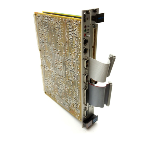
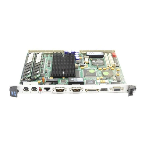
Xycom XVME-100 User manual

-~
ARTISAN
®
~I
TECHNOLOGY
GROUP
Your definitive source
for
quality
pre-owned
equipment.
Artisan Technology
Group
Full-service,
independent
repair
center
with
experienced
engineers
and
technicians
on staff.
We
buy
your
excess,
underutilized,
and
idle
equipment
along
with
credit
for
buybacks
and
trade-ins
.
Custom
engineering
so
your
equipment
works
exactly as
you
specify.
•
Critical
and
expedited
services
•
Leasing
/
Rentals/
Demos
• In
stock/
Ready-to-ship
•
!TAR-certified
secure
asset
solutions
Expert
team
ITrust
guarantee
I
100%
satisfaction
All
tr
ademarks,
br
a
nd
names, a
nd
br
a
nd
s a
pp
earing here
in
are
th
e property of
th
e
ir
r
es
pecti
ve
ow
ner
s.
Find the Acromag / Xembedded / Xycom XVME-100 at our website: Click HERE

•
KWH
RAM/ROM
MEMORY
MODULE
•
©XYCOM 1987
Printed in the United States of America
Part Number 74100-001
•
XYCOM
750 North Maple Road
Saline, Michigan 48176
(313) 429-4971

REVISION RECORD
REVISION DESCRIPTION
Aaaau,jaEaz21EED3 jal_____________
Im
all
MANUAL
P/N:
174100-001
This document contains proprietary information of Xycom Incorporated (Xycom). It shall not be
reproduced or copied without expressed written authorization from Xycom.
The information contained within this document is subject to change without notice. Xycom does not
guarantee the accuracy of the information and makes no commitment toward keeping it up-to-date.
Address comments concerning
this manual to:
XYCOM
Technical Publications Dept.
750 North Maple Rd.
Saline, Michigan 48176
•
e
•

XVME-100 Manual
March, 1987
CHAPTER
1
TABLE OF CONTENTS
TITLE
MODULE DESCRIPTION
PAGE
1.1 Introduction 1-1
1.2 Manual Structure 1-1
1.3 Module Operational Description 1-2
1.4 Specifications 1-3
LXVNIE-100 INSTALLATION
2.1 Introduction 2-1
2.2 Location of Components Relevant to Installation 2-I
2.3 Jumpers 2-4
2.4 Jumper Descriptions 2-5
2.4.1 VME Address/Memory Chip Sizc 2-5
2.4.2 Address Modifier Decode 2-10
2.4.3 Memory Device Speed 2-11
2.4.4 Memory Device Pinout 2-12
2.4.5 Memory Backup Power 2-15
2.4.6 Power Monitor 2-17
2.5 Installing Memory Chips on the XVME-100 2-19
2.6 Cardcage Installation Procedure 2-20
2.7 Installing a 6U Front Panel Kit (optional) 2-21
AVNIEbus CONNECTOR/PIN DESCRIPTION
BPOWER MONITOR
CDIAGRAM AND SCHEMATICS
DQUICK REFERENCE GUIDE
•
•
•

XVME-100 Manual
March, 1987
LIST OF FIGURES
FIGURE TITLE PAGE
1-I Operational Block Diagram 1-2
2-1 Location of Jumpers, Sockets, and Connector 2-I
2-lA Expanded Left Side of XVME-I00 2-2
2-IB Expanded Right Side of XVME-100 2-3
2-2 XVME-100 Memory Map 2-8
2-3 Addressing - 4 x Chip Size 2-9
2-4 Memory Chip Pinouts 2-13
2-5 Location of Jumper J34 2-15
2-6 Location of Jumpers and Test Points 2-18
2-7 Notched End of the Memory Chip 2-19
2-8 Installation of an XVME-945 6U Front Panel -)---,
LIST OF TABLES
TABLE TITLE PAGE
1-1 Memory Module Specifications 1-3
2-1 Jumper List 2-4
2-2 VME Base Address and Memory Chip Size Jumpers 2-6
2-3 Address Modifier Jumpers 2-10
2-4 Memory Device Speed Jumpers 2-11
2-5 Memory Device Pinout Jumpers 2-12
ii
•
•
•

vME-100 Manual
\17r,.11, 1987
•
•
•
Chapter 1
MODULE DESCRIPTION
1.1 INTRODUCTION
The XVME-100 RAM/ROM Memory Module is a single-high, VMEbus compatible
board, which can accommodate up to IM byte of RAM, EPROM, or mask
programmable ROM or 256K bytes of EEPROM. The module is designed with an on-
board battery backup circuit to provide power to CMOS RAM devices in the event
of a power failure.
The XVME-100 has eight 28/32-pin JEDEC sockets which arc logically arranged as 2
banks of 4 sockets each. Each bank is designed to employ memory devices of the
same type and speed, and each bank can be independently configured Ha jumpers)
in terms of:
•VME Address/Memory Chip Sizc
•Address Modifier Decode
•Memory Device Speed
•Memory Device Pinout
•Memory Backup Power
The XVME-100 RAM/ROM Memory Module has power down protection circuitry
which prevents data from being written to memory when the voltage falls below
4.75 Volts. The module also has the option of asserting SYSRESET under this
condition.
1.2 MANUAL STRUCTURE
The purpose of this first chapter is to introduce the user to the general
specifications and functional capabilities of the XVME-I00. Successive chapters will
develop the various aspects of module installation and operation in the following
progression:
Chapter One
Chapter Two
Ageneral description of the memory module, including
complete functional and environmental specifications,
VMEbus compliance information, and a block diagram.
Module installation information covering the location of
pertinent module components, jumper options, and standard
board installation information.
The Appendices are designed to introduce and reinforce a variety of module-related
topics including: Backplane signal/pin descriptions, a block diagram and schematics,
aquick reference section, and power monitor calibration procedures.
XVME-100 Manual
March, 1987
1.3 MODULE OPERATIONAL DESCRIPTION
Figure 1-I shows and operational block diagram of the memory module.
Figure 1-1. Operational 1312cl: Diagram
1-2
•
•
•

XVME-100 Manual
March, 1987
•
•
•
1.4 SPECIFICATIONS
Table 1-1 lists the XVME-100 Memory Module's characteristics and specifications.
Table 1-1. Memory Module Specifications
Characteristic
Maximum Mcmory Capacity:
Specification
2banks of 4 sites
EPROM 1M byte
RAM 1M byte
Mask Programmable ROM -- 1M byte
EEPROM256K bytes
Device Sizes Supported:
EPROM
RAM Mask
8K by 8 up to 128K by 8
8K by 8 up to 32K by 8
(EEPROM must have quick
write/polling technique
and must employ TTL logic
levels.)
Dcvicc Speeds Supported —— — — —100ns, 150ns, 200ns, & 250ns
Power Requirements
Battery Rating
Battery Life
VMEbus COMPLIANCE
+5V @ 900mA typ., IA max.
1.4Amp hours
6years typ. (using an 8-6264
Hitachi RAM or equivalent
device)
Complies with VMEbus Specifications, Revision C.1
•A24:D16/D08(EO) DTB Slave
•4 BUS GRANT INs are connected to their respective BUS GRANT
OUTs
•IACKIN is connected to IACKOUT
•SINGLE - 3U Form Factor
1-3

XVME-100 Manual
March, 1987
Table I-1. Memory Module Specifications (continued)
Characteristic Specification
ENVIRONMENTAL
Temperature
Operating
Non-operating
Humidity
Altitude
Operating
Non-operating
Vibration
Operating
Non-operating
0to 65 C (32 to 149 F)
40 to 85 C (-40 to 158 F)
5to 95% RH non-condensing
(Extreme low humidity
conditions may require special
protection against static
discharge)
Sea-level to 10,000 ft. (3048m)
Sea-level to 50,000 ft. (15240m)
5to 2000Hz
.015 inches
displacement
2.5 g peak
acceleration
5to 2000Hz
.030 inches
displacement
5.0 g peak
acceleration
peak-to-peak
(maximum)
peak-to-peak
(maximum)
Shock
Operating 30 g peak acceleration, 1 Imscc.
duration
Non-operating — — — — 50 g peak acceleration. 1 Imsec
duration
1-4
•
•
•

XVME-100 Manual
March, 1987
U1
x>
z
O
O
U2
r" to
02.
2
0
U3
'X 0
z
7,
0.-
0
O
DS1
DS2
B1
A
A
lr
A
B
0
U17
z>
nz
U18
r^
0Y.
U19
0
Z
-
ACAAA
B
/Th
C3 B
,!,•5 J38 .147
J39 J43 B
BA B Ain
J4 J9 RN3
U9 J5 J10 RN4
---\ i—Th
01 02 J6
,,, j7 J11 J12 I J13 1314 1J15 I J16
J17 J18 .2 22 L.N
r, U10
J19 J20 ,., w4
BAB A RN5
•Chapter 2
XVME-100 INSTALLATION
2.1 INTRODUCTION
This chapter explains how to configure the memory module prior to installation in a
VMEbus system. Included in this chapter is information on jumper options, jumper
locations, and power monitor circuit calibration and installation procedures.
2.2 LOCATION OF COMPONENTS RELEVANT TO INSTALLATION
The jumpers, memory sockets, and the VMEbus P1 connector on the XVME-100
Memory Module arc illustrated in Figure 2-1. Figure 2-lA show an expanded left
side of the board, and Figure 2-1B the right for clarification purposes.
U4
r-
0
U20
rra
-•-•
7.
R3 00Opi
U6
A
B
B
IJ1
TP2
00
TP1
RN2
U7 U8
1.148 I J49 1.150 1.151
RN8
7, U11 U12
U13 U14
J301 J31
IJ32 I J331
U15
U21
U23
RN6
U16
RN7
U22
C4
P1
32
Figure 2-1. Location of Jumpers, Sockets, and Connector
2-1

XVME-100 Manual
March, 1987
DS1
DS2
B1
A
B
•
•
z
0
A
A
B
A
B
A
B
U1
Ca
a)
Ca J38
J39
BA
U2
U18
=
C>
sz
A
OA
A
J42
J43 B
BA "
A
A
B
U3
U19
A
B
`g
U4
U20
J47 J481J49
RN8
Figure 2-1A. Expanded Lcft Side of XVME-100
2-2
J50 J51 cn
cn
•
•

XVME-100 Manual
March, 1987
U9 J4 J9 RN3
J5 J10 RN4
01/ 02 c—
CO
J6 J11 J12 1 J13 J14 J15 J16
J7
J17 J18 C- NC-
C.)A
C- U10
J19 J20
U11 U12
AC-
a)
B-•J
Ac_
co
B
C-
CD
U13 U14
•
•
•
R3
A
00D3
a) 33
co
J1
U5
TP2
00
TP1
U7
U6
RN2
U8
BAB A RN5
J30 J31
J32 J33
U15
U21
U23
RN6
U16
RN7
U22
32
P1
Figure 2-1B. Expanded Right Side of XVME-100
2-3

XVME-100 Manual
March, 1987
2.3 JUMPERS
Prior to installing the XVME-100 Memory Module, it will be necessary to configure
several jumper options. The configuration is dependant upon which type of memory
devices to be used. The following table shows a list of the jumpers and a brief
description of their use.
Table 2-1. Jumper List
Jurnper Description Section
J1
J2
J3
J4
J5
J6
J7
J8
J9
JI0
J11
J12
J13
J14
J15
J16
317
J18
J19
J20
J21
J22
J23
J24
J25
J26
J27
J28
J29
330
331
J32
J33
J34
J35
J36
J37
J38
J39
Power Monitor Calibration
Memory Type - bank 2
Memory Typc - bank 2
Speed Select - bank 2
Speed Select - bank 1
SYSRESET* Driver, enable
Data Access - bank 2
Program Access - bank 1
Data Access - bank 1
Program Access - bank 2
Supervisor Only - bank 1
VME Address - bank 1
Supervisor Only - bank 2
VME Address - bank 2
VME Address bank I
VME Address bank 1
VME Address bank 1
VME Address bank 1
VME Address bank 1
VME Address bank 1
VME Address - bank 1
Memory Type bank 2
VME Address - bank 2
VME Address bank 2
VME Address bank 2
VME Address - bank 2
VME Address bank 2
VME Address bank 2
VME Address bank 2
VME Address - bank 2
Battery, alternate power source
+5V STDBY, alternate power source
Memory Type - bank 2
Memory Typc - bank 2
Memory Type - bank 2
2-4
2.4.6
2.4.4
2.4.4
2.4.3
2.4.3
2.4.3
2.4.3
2.4.6
2.4.2
2.4.2
2.4.2
2.4.2
2.4.2
2.4.1
2.4.2
2.4.1
2.4.1
2.4.1
2.4.1
2.4.1
2.4.1
2.4.1
2.4.1
2.4.1
2.4.4
2.4.1
2.4.1
2.4.1
2.4.1
2.4.1
2.4.1
2.4.1
2.4.1
2.4.5
2.4.5
2.4.4
2.4.4
2.4.4
2.4.4
•
•
•

XVME-100 Manual
March, 1987
Jumper Description Section
J40 Memory Type - bank 1 2.4.4
J41 Memory Typc - bank 1 2.4.4
J42 Memory Typc - bank 1 2.4.4
J43 Memory Typc - bank 1 2.4.4
J44 Memory Type - bank 1 2.4.4
J45 Memory Type - bank 1 2.4.4
J46 Memory Type - bank 1 2.4.4
J47 Sizc Scicct - bank 2 2.4.1
J48 Size Scicct - bank 2 2.4.1
J49 Size Select - bank 2 2.4.1
J50 Sizc Select - bank 1 2.4.1
J51 Size Select - bank 1 2.4.1
J52 Size Select - bank 1 2.4.1
•
•
•
Table 2-1. Jumper List (continued)
2.4 JUMPER DESCRIPTIONS
The two banks arc independently configurable, via jumpers to define five different
memory module parameters, these parameters arc:
1. VME Address/Memory Chip Sizc
2. Address Modifier Decode
3. Memory Device Speed
4. Memory Device Pinout
5. Memory Backup Power
The following five subsections examines these jumper options in closer
showing specifically when and how jumpers should be configured.
2.4.1 VME Address/Memory Chip Size
12 jumpers exist for each bank (24 total) to define the VMEbus address and memory
chip size. Table 2-2 lists the jumpers and their definitions. The bank will occupy
aVMEbus address space of four times the memory chip size. The bank must be
assigned to a boundary which is a multiple of four times the memory chip size.
2-5

XVME-100 Manual
March, 1987
J28 J47 J48 J49 J16 J31 J30 J33
XIn In In
XIn In Out
XIn Out In
XIn Out Out
BOut In In
Table 2-2. VME Base Address and Memory Chip Size Jumpers
BANK 1
BASE ADDRESS BIT =1 =0
A23
A22
A21
A20
A19
A18
A17
A16
A15
J14 Out
J23 Out
J21 Out
J22 Out
J24 Out
J20 Out
J18 Out
J19 Out
J17 Out
J14 In*
J23 In*
J21 In*
J22 In*
J24 In*
J20B*
J18B*
J19B*
.117B*
*Factory shipped
configuration
Device Size In Bits J17 J19 J18 J20 J50 J51 J52 J14 J23 J21 J22 J24
8K x8
16K x 8
32K x 8
64K x 8
128K x 8
X
A
A
A
A
X
X
A
A
A
X
X
X
A
A
X
X
X
X
A
In
In
In
In
Out
In
In
Out
Out
In
In
Out
In
Out
In
XXXXX
X= Use to define state of corresponding
base address bit per above chart
BANK 2
BASE ADDRESS BIT =1 =0
A23
A22
A21
A20
A19
A18
A17
A16
A15
J16 Out
J31 Out
J30 Out
J33 Out
J32 Out
J28 Out
J26 Out
J29 Out
J27 Out
J16 In*
J31 In*
J30 In*
J33 In*
J32 In*
J28A*
J26A*
J29A*
J27A*
*Factory shipped
configuration
Device Size In Bits J27 J29 J26
8K x8
16K x 8
32K x 8
64K x 8
128K x 8
X
B
B
B
B
X
X
B
B
B
X
X
B
B
J32
XXXXX
X= Use to define state of corresponding
base address list per above chart
2-6
•
•
•

XVME-100 Manual
March, 1987
•
•
The following is an example of the jumpering required to install 32K x 8 EPROMs
in bank 1.
EXAMPLE:
27256 32K x 8 EPROMs are to installed in bank 1 with a VMEbus base address of
8E0000 Hcx.
J17 A
J19 A
J18 OUT
J20 OUT
J50 IN
J51 OUT
J52 IN
JI4 OUT
J23 IN
J21 IN
J22 IN
J24 OUT
Bank 1will reside in memory address:
8E0000 Hex. through 8FFFFF Hex.
Figure 2-2 shows the memory map for the XVME-100, and Figure 2-3 shows the
bank addressing four times the memory chip size.
2-7

XVME-100 Manual
March, 1987
U19 U3
U20 U4
U17 U1
U18 U2
WORD ADDRESS
EVEN BYTES ODD BYTES
BANK 1
EVEN BYTES ODD BYTES
BANK 2
BASE ADDRESS +4 X DEVICE SIZE - 2
BASE ADDRESS + 2 x DEVICE SIZE
—BASE ADDRESS + 2 x DEVICE SIZE - 2
BASE ADDRESS
WORD ADDRESS
BASE ADDRESS +4 X DEVICE SIZE - 2
BASE ADDRESS + 2 x DEVICE SIZE
—BASE ADDRESS + 2 x DEVICE SIZE - 2
BASE ADDRESS
Figure 2-2. XVME-100 Memory Map
2-8

XVME-100 Manual
March, 1987
•
BANK #0
•
4
(4x DEVICE SIZE IN BYTES)
n= 0, 1, 2, 3, ..
BASEADDRESS =
nx (4x DEVICE SIZE IN BYTES)
Figure 2-3. Addressing - 4 x Chip Size
2-9

XVME-100 Manual
March, 1987
Jumpers Description
J13 In*
J13 Out
J11 In*
J11 Out
J10 In*
J10 Out
Supervisor Only AM2 = I
Supervisor & Non-privileged AM2 = don't care
Data Access Responds to Address Modifier codes
No Data Access Won't respond to 3DII or 391-1
Program Access 3EH or 3A1l
No Program Access Won't respond to 3EH or 3A11
2.4.2 Address Modifier Decode
The address modifier decode uses three jumpers for each bank (6 total). Both
banks reside in the standard A24 address space. The first jumper is the supervisor
select, when the jumper is in, the bank will respond only to supervisor accesses,
when the jumper is out, the bank will respond to supervisor and non-privileged
accesses. During each access of a bank, that bank's LED (green) on the front
panel, will momentarily light.
The second jumper is the data space select, when this jumper is in, the bank will
respond to data accesses, when out, the bank won't respond to data accesses.
The third jumper is the program space select, when the jumper is ill, the module
will respond to program accesses, when out, the module won't respond to program
accesses.
Table 2-3 lists these three jumpers and their definitions.
Table 2-3. Address Modifier Jumpers
BANK 1
BANK 2
Jumpers Description
J15 In*
J15 Out
J9 In*
J9 Out
J12 In*
J12 Out
Supervisor Only AM2 = 1
Supervisor & Non-privileged AM2 = don't care
Data Access Responds to Address Modifier codes
No Data Access Won't respond to 3DH or 391-1
Program Access 3E11 or 3AH
No Program Access Won't respond to 3E11 or 3All
*= Factory shipped configuration
2-10
•
•
•

XVME-100 Manual
March, 1987
Speed Select Jumpers
J6 J7
100ns
150ns
200ns
250ns
Out
Out
In
In*
Out
In
Out
In*
Speed Select Jumpers
J4 J5
100ns
150ns
200ns
250ns
Out
Out
In
In*
Out
In
Out
In*
These three jumpers arc independent of each other. When both the data space
select and the program space select jumpers arc out, the bank will be disabled from
VMEbus accesses.
2.4.3 Memory Device Speed
Two jumpers exist for each bank (4 total) to define the speed of the memory
devices. Selections are 100, 150, 200, and 250 ns devices. Table 2-4 lists the
jumpers and speed definition for each device.
Table 2-4. Memory Device Speed Jumpers
BANK 1
•
•
BANK 2
*= Factory shipped configuration
VMEbus access timing is a function of the memory device speed of the bank being
accessed. Data strobe asserted to DTACK* asserted will typically be 100 ns plus
the chosen access time. Data strobe negated to DTACK* negated will be 50 us
typical.
2-11
Table of contents
Other Xycom Control Unit manuals

Xycom
Xycom XVME-601 User manual

Xycom
Xycom XVME-654 User manual

Xycom
Xycom XVME-212 User manual

Xycom
Xycom XVME-675 User manual

Xycom
Xycom XVME-530 User manual

Xycom
Xycom XVME-678 User manual

Xycom
Xycom XVME-951 User manual

Xycom
Xycom XVME-976 User manual

Xycom
Xycom XVME-682 User manual

Xycom
Xycom XVME-678 User manual
Popular Control Unit manuals by other brands

SetonixSynth
SetonixSynth Doug Assembly

Cameron
Cameron TYPE 31 Installation, operation and maintenance manual

Samson
Samson 3310/AT Mounting and operating instructions

Telcoma
Telcoma K100 Instructions for installing

Rockwell Automation
Rockwell Automation DeviceNet ArmorBlock A Series installation instructions

Vertiv
Vertiv R48-500 user manual