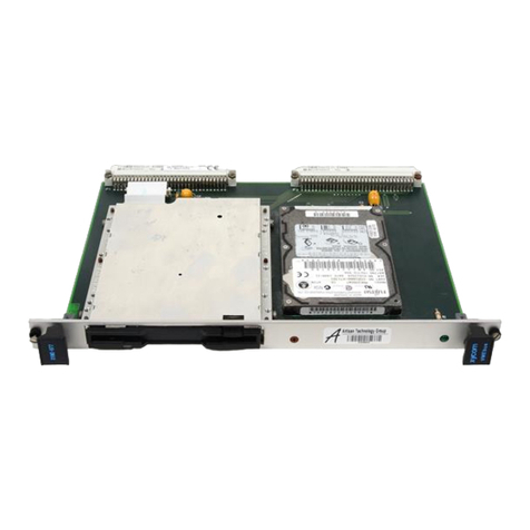
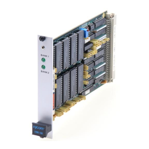
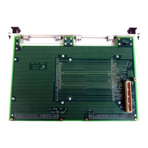
Xycom XVME-682 User manual

-~
ARTISAN
®
~I
TECHNOLOGY
GROUP
Your definitive source
for
quality
pre-owned
equipment.
Artisan Technology
Group
Full-service,
independent
repair
center
with
experienced
engineers
and
technicians
on staff.
We
buy
your
excess,
underutilized,
and
idle
equipment
along
with
credit
for
buybacks
and
trade-ins
.
Custom
engineering
so
your
equipment
works
exactly as
you
specify.
•
Critical
and
expedited
services
•
Leasing
/
Rentals/
Demos
• In
stock/
Ready-to-ship
•
!TAR-certified
secure
asset
solutions
Expert
team
ITrust
guarantee
I
100%
satisfaction
All
tr
ademarks,
br
a
nd
names, a
nd
br
a
nd
s a
pp
earing here
in
are
th
e property of
th
e
ir
r
es
pecti
ve
ow
ner
s.
Visit our website - Click HERE

NIM=862
VMEbus PC/AT
Processor
Module
1989 XYCOM, INC.
Printed in the United States of America
Part Number 74682-001
XYCOM
750 North Maple Road
Saline, ivlichigan 48176
(313) 429-4971
Artisan Technology Group - Quality Instrumentatio Guaranteed I (888) 88-SOURCE

XYCOMREVISION RECORD
Revision Description Date
AManualReleased 2/88
BManualUpdatedandReleased 5/88
CManualUpdatedandReleased 10/89
Trademarks
•IBMPC/XT,PC/AT,EGA,CGA,andMDAareregisteredtrademarksofthe International
BusinessMachines Corporation
•HerculesisaregisteredtrademarkoftheHerculesComputerTchnology Corporation
•iAPXisaregisteredtrademarkoftheIntel Corporation
•ROMBIOSPLUSisaregisteredtrademarkofthePheonixTechnologies Corporation
Copyright Information
ThisdocumentiscopyrightedbyXycomIncorporated(Xycom)andshallnotbereproducedorcopiedwithout expressed
writtenauthorizationfrom Xycom.
Theinformationcontainedwithinthisdocumentissubjecttochangewithoutnotice.Xycomdoesnot guarantee the
accuracyoftheinformationandmakesnocommitmenttowardkeeping itupto date.
Addresscomments concerning
this manual to:
16;11 xycom
Tech ni cal Publications Dept.
750NorthMaple Road
Saline, Michigan 48176
xycom
PartNumber: 74682-001 C
artisanTechnologyGroup-Quality Instrume
ation ... I(888)88 I

XVME-682 Manual
October, 1989
CHAPTER
1
TITLE
INTRODUCTION
PAGE
1.1 Introduction 1-1
1.2 Manual Structure 1-2
1.3 XVME-682Two-Card Architecture 1-3
1.3.1 TheXVME-682CPU Module 1-3
1.3.2 TheXVME-682 I/O Module 1-3
1.3.3 XVME-682BusSignal Interfaces 1-3
1.4 Reference Documents 1-4
1.5 XVME-682CPUModuleOperational Description 1-5
1.6 XVME-682 I/OModuleOperational Description 1-7
1.7 Specifications 1-9
2XVME-682CPUMODULE CONFIGURATION
2.1 Introduction 2-1
2.2 Locations ofComponentsRelevant to Installation 2-1
2.3 Jumpers 2-6
2.3.1 Monitor Selection 2-6
2.3.2 KeyboardPort Enable 2-6
2.3.3 AuxiliaryMaskable Interrupts 2-6
2.3.4 VMEbus Interrupts 2-7
2.3.5 Dual-Port Interrupts 2-7
2.3.6 AuxiliaryNon-Maskable Interrupts 2-7
2.3.7 VMEbusSlave Interface 2-8
2.3.8 VMEbusSlaveInterface Addressing 2-8
2.3.9 VMEbusMaster Interface 2-9
2.3.10 EPROM 2-9
2.3.11 VMEbus"Slot1" Functions 2-9
2.3.12 SYSRESET 2-10
2.3.13 VMEbusArbitration Levels 2-10
2.3.14 SupervisorandAddress Modifier Codes 2-10
2.3.15 SerialandParallelPort Unit Levels 2-10
2.3.16 AT Port Interrupt Levels 2-11
2.3.17 SerialPort Configuration 2-11
2.3.18 Reserved Jumpers 2-12
2.5 XVME-682CPUModulePinout Descriptions 2-13
2.5.1 COM1and COM2 2-13
2.5.2 LPTI 2-14
2.5.3 Keyboard Connector 2-14
2.5.4 Speaker Jack 2-14
TABLEOF CONTENTS
t..-tinn
Technology
Group -
Quality
Instrum
tation ...
Guaranteed


XVME-682 Manual
October, 1989
TABLE TITLE PAGE
1-1 XVME-682 Versions 1-1
1-2 Module Specifications 1-9
2-1 AuxiliaryMaskableInterruptJumper Settings 2-6
2-2 VMEbusInterrupt Jumpers 2-7
2-3 AuxiliaryNon-Maskable InterruptJumper Settings 2-7
2-4 VMEbusSlaveInterfaceAddressing Jumpers 2-8
2-5 EPROMSelection Jumpers 2-9
2-6 Slot1 Jumpers 2-9
2-7 VMEbusArbitration Level Jumpers 2-10
2-8 Serial&ParallelPort UnitLevel Jumpers 2-10
2-9 AT PortInterruptLevel Jumpers 2-11
2-10 SerialPort Configuration Jumpers 2-11
2-11 ReservedJumper Configurations 2-12
2-12 SerialRS-232 2-13
2-13 SerialRS-422 2-13
2-14 Parallel Port 2-14
2-15 Keyboard Connector 2-14
3-1 EPROMJumper Settings 3-6
3-2 MonitorSelectionSwitch Settings 3-7
3-3 Video Connector 3-8
3-4 LightPenInterface Connector 3-8
3-5 Feature Connector 3-9
3-6 FloppyDisk Connector 3-10
3-7 HardDiskControl Connector 3-10
3-8 HardDisk#1Data Connector 3-11
3-9 HardDisk#2Data Connector 3-12
3-10 PC/ATInterfaceConnectorP2(XVME-682/2& /4 Only) 3-13
3-11 PC/ATInterfaceConnectorP2(XVME-682/1 & /3 Only) 3-15
3-12 PC/ATInterfaceConnectorP3(XVME-682/1 & /3 Only) 3-16
5-1 SupportedFloppyDiskDrive Specifications 5-2
5-2 HardDiskDrives Supported 5-3
LISTOF TABLES
Quality tation ... 1(888)88-SOURCE1 www.artisantg.com
rumen

XVME-682 Manual
October, 1989
RAM CONNECTOR
1M 4M LOCAL P2
XVME-682/1
• •
XVME-682/2
• •
XVME-682/3 • •
XVME-682/4 • •
Chapter 1
MODULE DESCRIPTION
1.1 INTRODUCTION
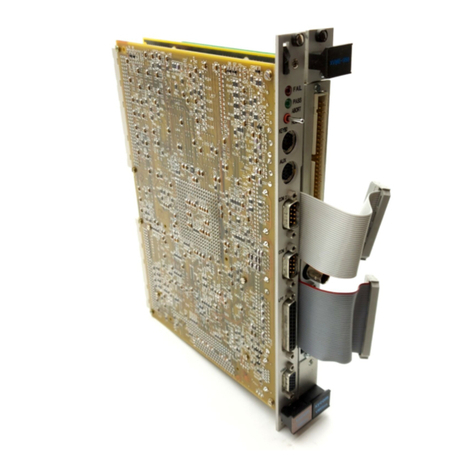
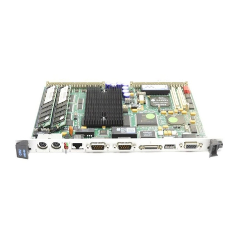
TheXVME-682VMEbusPC/ATProcessorModule isdesigned tocombine the high-
performanceandruggedizedpackaging oftheVMEbuswiththebroadapplication software
base oftheIBMPC/ATstandard.Themodule is fullyAT-compatible,capable of running
standardPC/AT software.
TheXVME-682 iscomprised oftwoVMEbus-compatible,6U(double-high)cards:the CPU
Moduleand the I/OModule. Thisuniquetwo-cardarchitecture isdiscussed later in this
chapter.
TheXVME-682comes in fourversionsdependingonthememorydesiredandthe mounting
locations oftheboards relative tooneanother.Thetwomemoryand configuration options
canbeselected inanycombination. Thisprovides for four versions.
ThememoryoptionsavailableontheXVME-682areeither1 or4M RAM.
Thelocationoptiongivestheuserthe ability tomounttheCPUand I/Oboards together or
innon-adjacentVMEbusbackplaneslots.Whentogether,thesharedPC/ATsignalsare passed
betweentheboards viaaxx-pinconnector. Inthenon-adjacentversion,thePC/AT signals
arerouted viatheVMEbusP2 backplane.
Table 1-1belowgivestheconfigurationoptions,and theirxycom designation.
Table 1-1XVME-682 Versions
1-1
-Quality Ins
tation ...Guaranteed I(888)88-SOURCEI www.artisantg.com
men

XVME-682 Manual
October, 1989
1.3 XVME-682TWO-CARD ARCHITECTURE
1.3.1 TheXVME-682CPU Module
TheXVME-682CPUModuleusesan80286microprocessor withsoftware-selected speeds of
10,8or6MHz.Memory isavailableaseither1Mbyteor4Mbytedual-portedRAM(with one
waitstate).BoththeVMEbusandPC/ATinterfacesresideon thisboard.Other XVME-682
CPUfeatures include:
•An optional80287mathco-processor
•FullIBMAT motherboard features
•VMEbusmaster,slaveand interrupthandler interfaces
•A"RealModeWindow"whichallows allVMEbuslocations tobeaccessed while the
processor is in"real mode"
•Control/Status registers
•WatchDog Timer
•VMEbus"Slot1" functions
•Threesoftware-configurableports(2serialand1 parallel)
•IBMPC/ATbusaccessibility viaVMEbusP2connector oroptionallocal connector
1.3.2 TheXVME-682 I/O Module
TheXVME-682 I/OCardprovidestheinterfacebetweentheXVME-682CPUcardand the
floppydisk,hard diskandgraphics controller.Featureson theXVME-682 I/O Module
include:
•EGA,CGA,MDA,andHerculesgraphics support
•256K ofvideo RAM
•IBMPC/AT-compatibleWinchesterandfloppydisk controller
•Control ofup totwoWinchester-typeharddisk drives
•Control ofup totwofloppydisk drives
1.3.3XVME-682BusSignal Interfaces
TheXVME-682CPUand I/Oboardsareunited viaalocalbus.ThisallowstheCPU board
tocommunicate directly withthegraphics ordisk-controller circuitry without tyingup the
VMEbus.VMEbussignalsarecarriedbytheP1 connector.
TheXVME-682 I/OmodulerequiresthePC/XTbus forproperoperation of its graphics
controller circuitry. Italsorequiresthe fullPC/ATbus foroperation ofthedisk-controller
circuitry.
ThePC/XTbus isplacedonRowsA &C oftheVMEbusP2backplane connectoron all
versions oftheXVME-682.Theremainder of thesignalsrequired forthePC/ATbus are
placedeitherontheRowB oftheVMEbusP2backplaneconnector, orona local connector
(P3).
TheXVME-682/1andXVME-682/3aredesigned toallowuse ofa32-bitprocessor inthe same
backplaneastheXVME-682.Thetables inAppendixCdescribethesignalsassignedfor the
variousoptions ofthe XVME-682.
1-3
Group -QualityInstrurentation ...Guaranteed I(888)88-SOURCEI www.artisantg.com
XVME-682 Manual
October, 1989
1.5 XVME-682CPUMODULEOPERATIONAL DESCRIPTION
Figure1-1 illustratesthe functionality oftheXVME-682CPUcard. A descriptionof the
components isgivenonthe opposite page.
PC/ATBUS I/F
WATCHDOG
TIMER
ROM
BIOS 80286
CPU
KEYBOARD
I/F
LOCALAT BUS
80287
NPX
MATH COPROCESSOR
(OPTIONAL)
VMEbus
BUFFERS
1.4MBYTES DUAL-
PORTED RAM
VMEbus
MASTER/SLAVE I/F
COM1 COM
TWO SERIAL
PORTS
BATTERY-BACKED
TOD CLOCK
Figure1-1XVME-682CPUCardBlock Diagram
1-5
LPT 1
PARALLEL
INTERFACE
uali Instrrentation ...Guaranteed I(888)88-SOURCEI www.artisantg.com
GrOUP Q ty

XVME-682 Manual
October, 1989
1.6 XVME-682 I/OMODULEOPERATIONAL DESCRIPTION
Figure1-2 illustratesthe functionality oftheXVME-682CPUcard. A descriptionof the
components isgivenonthe opposite page.
ROM BIOS
SECTOR
BUFFER
82A436 BUS
INTERFACE
DISPLAY
82C435 EGA
CONTROLLER
PC/AT BUS
WD11C00C-22
PC/AT INTERFACE
CONTROLLER
WD1015 BUFFER
MANAGER CONTROL
PROCESSOR
WD10C2OB
DATA SEPARATOR
WINCHESTER DATA
CONNECTOR
FLOPPY CONNECTOR
WD37C65
FLOPPY DISK
CONTROLLER
WD2010
WINCHESTER
DISK CONTROLLER
WINCHESTER DRIVE
CONTROL
Figure1-2XVME-682 I/OCardBlock Diagram
1-7
Tech nol ogy Group-QualityInstrumntation ...Guaranteed I(888)88-SOURCEI www.artisantg.com

XVME-682 Manual
October, 1989
1.7 SPECIFICATIONS
Table 1-2containsthefunctionalspecificationsforthe XVME-682.
Table 1-2XVME-682Module Specifications
SPECIFICATION
Mechanical
Processor
DESCRIPTION
Processor Speed
Mathcoprocessor (Optional)
CoprocessorSpeed
ResidentFirmware
Graphics Controller
Floppy-disk Interface
Hard-disk Interface
On-board Memory
Serial Ports (2)
Parallel Interface
RealTime Clock
Environmental
Temperature
Operating
Non-operating
Humidity
80286
6,8,or10MHz,software-selected
80287
8MHz
CPUPhoenixROMBIOS PLUS
I/O PhoenixEGA BIOS
EGA/CGA/MDAHercules Monochrome
SA450
ST506
Dual-portedRAM: 1 or4 MBytes
EPROMonCPUmodule:128KBytes(2 sockets)
EPROMon I/Omodule:64KBytes(1 socket)
8250/NS16450 compatible
Centronics compatible
Motorola146818A compatible
0to65 C(32 to149 F)
40 to85 C(-40 to185 F)
5to95%relative,non-condensing
1-9
.•_- Group-
Quality
-SOURCE
I www.artisantg.com

XVME-682 Manual
October, 1989
Chapter 2
XVME-682CPUMODULE CONFIGURATION
2.1 INTRODUCTION
Thischapterprovides theinformationnecessary toconfigureand install the XVME-682
PC/ATCPU Module.
NOTE
TheXVME-682CPUandI/Omodulesobtain power
fromboththeVMEbusPIandP2 backplanes. Both
backplanesmustbeinstalled forproper operation.
2.2 LOCATIONSOFCOMPONENTSRELEVANTTO INSTALLATION
JumpersandconnectorlocationsontheXVME-682CPUare illustrated inFigure2-2A for
RevisionLevelA, Figure2-2B forRevisionLevelB,andFigure2-2C forRevision Level C.
Theboardrevision level islocatedonthebackside ofthemodule(see Appendix A).
BeforemodifyingthejumpersontheXVME-682themodulesmustbeseparated(see Figure
2-1 forscrewlocations). IfyouhaveanXVME-682/1 orXVME-682/3(sharedPC/AT signals
passedthrough a localconnector),removethe fourscrewsandtwostandoffs holding the
boardstogetherandseparatethem(seeFigure2-1).DONOTbendthe circuitcards. The
XVME-682/2andXVME-682/4boardsshouldnotbe conncted.
2-1
Quality In tion ...Guaranteed I(888)88-SOURCEI www.artisantg.com
rumenta

A
XVME-682 Manual
October, 1989
As
ED •
J61
B
•
J43
•ii •
A
•i••
A• B • A •
J39 J40 J41
J38
•• •
A•8 • B
B
•Al • A
J36 j37
•
c•J32
•
A
•
••C • •
J26
J62
J63 AA8
J57 •
AA • •
J58 B A
•• J42 •B Afl I IA
ara_____1111111/MAI
J59I J56
AMI NOmmenn V
L41111WA=975 IMMIIMuummliMiamminera‘
J60
J46 J44\
J45/ flitM
J30
•r-
Af J I P2
J33
P3
1111111111111M1
rl�l■Rij11■r■■■■■L.
J31/
•
A
J55E3
J1
P1
J54—..
J53f
J47 J48
J5
J52 I \J50
J51
J15
J19 J14
J20 \ J13
18 J6
J21--\ ji7 /---rJ12
J22 j7 J16
r
•
•AB
J11
J9 J8 •• • •
AB C D
Figure2-2AXVME-682CPUModuleJumperandConnector Locations
(Artwork Revision A)
2-3
J4
AB CD
•• • •
BC D
•• • •
J25
J10
J2
J3
ArtisanTechnologyGroup -QualityInstrumepation ... I(888)88-SOURCE I www.artisantg.com

XVME-682 Manual
October, 1989
AB
J62
t• •I
••
AB•
J43
AB•J63
J61
B—• A. •
•
AB- A
•
J39 J40 J41
•
•
J38
•
A•
B- A
•
•
DC•J32
•
•
B
•
•
•
•
•
•
•
J36 J37
•
•
CJ26
•
•
B•
•
•
A
BJ59
••BA
••
J58
J5710 •j•
•BA
••
J56
UUUUUUUU UUUUUU
J31
•B
A
•
•
•••
AB -B
••
J42 •8 A A
P1
•AB
J9
••
••
J47 J48
J8
••
J11
•• • •
AB c
Figure2-2CXVME-682CPUModuleJumperandConnector Locations
(Artwork Revision C)
2-5
J12
••
AB C D
•• • •
AB C D
J4F• •I • • • •
J10
J2
J3
ArtisanTechnologyGroup-Quality
Instrunnentat
on ...Guaranteed I(888)88 I
www.artisantg.com

XVME-682 Manual
October, 1989
JUMPER VMEBUS INT
LEVEL
J23 1
J22 2
J21 3
J24 4
J19 5
J18 6
J17 7
JUMPER ANMI SOURCE
J62
J51
J52
J50
Abort Button
ACFAIL
SYSFAIL
Watchdog Timer
2.3.4VMEbusInterrupts(J17,J18, JI9,J21,J22,J23, J24)
The80286CPUchipcanreceiveinterruptsfrom allsevenVMEbus interruptlevels. Each
VMEbus interruptlevelhasacorrespondingjumper toenable ordisable its function. When
thejumper is IN,the interrupt level isenabled.Whenthejumper isOUT,the interrupt level
isdisabled. Table2-2 liststhesevenjumperscorresponding tothesevenVMEbus interrupt
levels.The default is allexceptJ20are IN.
Table 2-2VMEbusInterrupt Jumpers
2.3.5 DualPort Interrupts (J1)
OtherVMEbusmastersmay interrupttheXVME-682byreadinganyone ofthe lower 16
bytes ofthemodule'sdual-portRAM.Jumper JI isused toenableanddisable this type of
interrupt.When JI is IN,thedual-port interrupt isenabled.Whenthejumper isOUT, the
interrupt isdisabled.The default is IN.
2.3.6AuxiliaryNon-MaskablcInterrupts(ANMI)(J50,J51,J52, J62)
FourAuxiliaryNon-Maskable Interrupts(ANMI)havebeenadded to thebasicIBM AT
architecture.Theyare: theAbort Button,theWatchdogTimer,SYSFAIL,and ACFAIL.
Each ofthe fourANMIs isassigned toajumper thatcanbeused topermanently disable its
function.Whenthejumper is IN,theANMIsourcecangeneratean interrupt.When the
jumper isOUT,theANMIsourcemaynotgeneratean interrupt.
Table 2-3 liststheANMIsand theircorrespondingjumpers.The default is all IN.
Table 2-3AuxiliaryNon-Maskable Interrupt Jumpers
2-7
ArtisanTechnologyGroup-QualityInstrumentation ...Guaranteed (888)88-SOURCEI www.artisantg.com

XVME-682 Manual
October, 1989
JUMPER EPROM
TYPE
J47 J48
BB27512
AB27256
AA27128
AA2764
JUMPER ENABLED DISABLED
J6
J5
J15
J9
J34
IN
IN
IN
A
IN
OUT
OUT
OUT
B
OUT
2.3.9VMEbusMaster Interface (J54)
TheVMEbusmasterinterfaceallowstheCPUchip tobecomeamaster or interrupt handler
ontheVMEbus.Themasterinterface isinvokedwhenevertheCPUchiphas accessed the
VMEbusstandardaddressspace,theshort I/Ospace, ortheIACKaddressspace. VMEbus
cyclesmaybeterminated withBERR orDTACK.JumperJ54 isprovided to disable the
BERRNMIsignalgeneration.Whenthejumper is IN,theBERRsignal willgeneratean NMI.
When it isout,theBERRsignal willnotgenerateanNMI.The default is IN.
2.3.10EPROM(J47, J48)
Two jumpersdefinethetype ofEPROMattheoddbytelocation(U34)andtheeven byte
location(U46).TheyareJ47andJ48.Table2-5showshowthesetwojumpersare configured
toselectthetype ofEPROMontheXVME-682CPUmodule.The default isJ47Aand J48B
(256K EPROMs).
Table 2-5EPROMSelection Jumpers
2.3.11VMEbus"Slot1"Functions(J5,J6,J9,J15, J34)
TheXVME-682cansupplytheVMEbusfunctionsassociated withSlot1(SYSRESET driver,
IACKdaisychain driver,single-level arbiter,bustimeout,andSYSCLK driver). These
functionsareenabledanddisabledasagroupbyjumpersJ5,J6,J9,J15 &J34).Table 2-6
illustratestheconfigurationsofthesejumpersand theirrelationships totheSlot1 functions.
Thedefault is all IN, withJ9set to A.
Table 2-6 Slot1 Jumpers
2-9
ArtisanTechnologyGroup -QualityInstrumentaon ...

XVME-682 Manual
October, 1989
JUMPER INT LEVEL
J27
J30
J29
J28
IRQ7
IRQ5
IRQ4
IRQ3
JUMPER SETTINGS
RS-232 RS-422
J36 B A
J37 BA
J38 A B
J39 BA
340 AB
J41 B A
J42 A B
J43 B A
J56 B A
J57 AB
J58 B A
J59 BA
J61 B A
2.3.16 AT PortInterruptLevels(J27,J28,J29, J30)
The82C605chipcan interrupttheAT architectureon fourlevels. Ajumper is provided for
eachlevel toenableanddisabletheinterruptonthat particularlevel.Whenthejumper is IN,
the interrupt isenabled.WhenOUT, the interrupt isdisabled. Table 2-9shows the
correspondingjumpersand interruptlevels.The default is all IN.
Table 2-9 AT Port InterruptLevel Jumpers
2.3.17SerialPortConfiguration(J36,J37,J38,J39,J40,J41,J42,J43,J56,J57,J58,J59, J61)
Serialport#1 isRS-232only(COM1 defaultconfiguration).Serial port#2(COM2 default
configuration)canbejumper-configuredaseitherRS-232 orRS-422.Table2-10shows how
theserial portconfigurationjumpersmustbeset forchoosingthe different porttypes for
serialport#2.The default isRS-232.
NOTE
XVME-682moduleswithRevisionA artwork may
onlyhavetheCOM2PortconfiguredasRS-232.
Table 2-10 SerialPort Configuration Jumpers
2-11
ArtisanTechnologyGroup-QualityInstrumentaion ... I(888)88-SOURCEI www.artisantg.com
XVME-682 Manual
October, 1989
PIN SIGNAL
PIN SIGNAL
1CD 6DSR
2RXD 7RTS
3TXD 8CTS
4DTR 9RI
5GND
PIN SIGNAL
PIN SIGNAL
1TXD- 6RXD-
2TXD+ 7RXD+
3RTS- 8CTS+
4RTS+ 9CTS-
5GND
2.5 XVME-682CPUMODULEPINOUT DESCRIPTIONS
Thefollowingsections illustratethesignalspassedbytheportsandconnectorsonthe XVME-
682CPU module.
2.5.1COM1and COM2
COM1 islabelledJK4onthe frontpanel,andCOM2 islabelledasJK3.Bothare9 pin D-
typeconnectors.COM1 isadedicatedRS-232standard port,whileCOM2canbe configured
touseeithertheRS-232 orRS-422standards.The factorysetting isboth toRS-232.The RS-
232andRS-422pinoutsaregiven below.
Table 2-12 SerialRS-232
Table 2-13 SerialRS-422
Someearlierversions oftheXVME-682(Rev.A)canonlyhaveCOM2set toRS-232.
2-13
ArtisanTechnologyGroup -QualityInstrunnentiion ...GuaranteedI(888) -SOURCEI www.artisantg.com

XVME-682 Manual
October, 1989
Chapter 3
XVME-682 I/OMODULE CONFIGURATION
3.1 INTRODUCTION
Thischapterprovidestheinformationnecessary toconfiguretheXVME-682 I/O Module.
NOTE
TheXVME-682CPUandI/Omodulesobtain power
fromboththeVMEbusP1andP2 backplanes. Both
backplanesmustbeinstalled forproper operation.
3.2 LOCATIONSOFCOMPONENTSRELEVANTTO INSTALLATION
Jumpers,connectorsandswitchlocationson theXVME-682 I/Omoduleare illustrated in
Figure 3-lAforRevisionLevelA, Figure3-1B forRevisionB,andFigure3-1C for Revision
LevelC. Defaultjumperandswitchsettingsarelisted inAPPENDIXA of this manual.
BeforemodifyingthejumpersontheXVME-682themodulesmustbeseparated(see Figure
2-1 forscrewlocations). IfyouhaveanXVME-682/1 orXVME-682/3(sharedPC/at signals
passedthroughalocalconnector),removethe fourscrewsandtwostandoffs holding the
boardstogetherandseparatethem(seeFigure2-1).DONOTbendthe circuitcards. The
XVME-682/2andXVME-682/4boardsshouldnotbe conncted.
3-1
ArtisanTechnologyGroup -QualityInstrumentton ...
Guaranteed

XVME-682 Manual
October, 1989
J8
•• •
A B
J4
•A
•B
J14
AB
41.0 01
•• •
AB
J13
•
B•
•
•
B
A•
A
B
•
•
•
•
J11
J12
J1
•
J7 e A
••
°IJK4
JK3 JK2
JK1 0
j1V
J9
J3 J2\LI
P3
ULJULJUULJULJULILLUJIIJU
P2
0000
SW1P7 11.-1
P6P5 I
-J6
IP1
Figure3-1BXVME-682 I/OModuleJumper,ConnectorandSwitch Locations
(ForRevision Level B)
3-3
J5
•A
B
•
1ArtisanTechnologyGroup-Qualitylnstrumentatin...Guaranteed I(888)88-SOURCEI www.artisantg.com
This manual suits for next models
4
Table of contents
Other Xycom Control Unit manuals

Xycom
Xycom XVME-212 User manual

Xycom
Xycom XVME-100 User manual

Xycom
Xycom XVME-977 User manual

Xycom
Xycom XVME-976 User manual

Xycom
Xycom XVME-601 User manual

Xycom
Xycom XVME-653 User manual

Xycom
Xycom XVME-951 User manual

Xycom
Xycom XVME-956 Series User manual

Xycom
Xycom XVME-654 User manual

Xycom
Xycom XVME-976/202 User manual