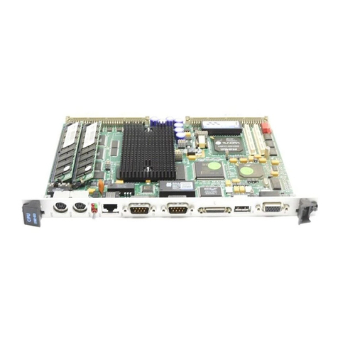
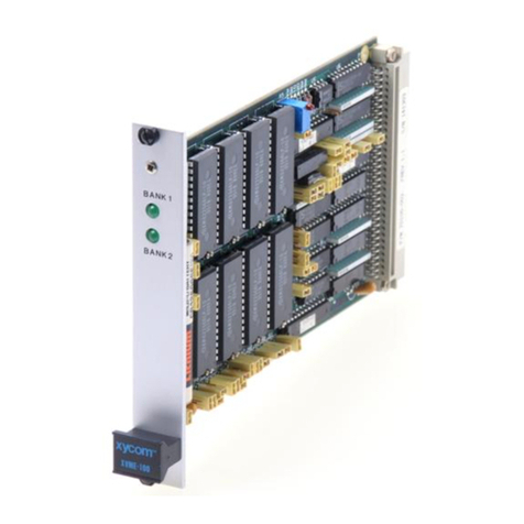
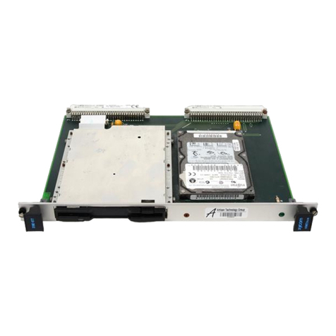
Xycom XVME-675 User manual

Artisan Technology Group is your source for quality
new and certied-used/pre-owned equipment
• FAST SHIPPING AND
DELIVERY
• TENS OF THOUSANDS OF
IN-STOCK ITEMS
• EQUIPMENT DEMOS
• HUNDREDS OF
MANUFACTURERS
SUPPORTED
• LEASING/MONTHLY
RENTALS
• ITAR CERTIFIED
SECURE ASSET SOLUTIONS
SERVICE CENTER REPAIRS
Experienced engineers and technicians on staff
at our full-service, in-house repair center
WE BUY USED EQUIPMENT
Sell your excess, underutilized, and idle used equipment
We also offer credit for buy-backs and trade-ins
www.artisantg.com/WeBuyEquipment
REMOTE INSPECTION
Remotely inspect equipment before purchasing with
our interactive website at www.instraview.com
LOOKING FOR MORE INFORMATION?
Visit us on the web at www.artisantg.com for more
information on price quotations, drivers, technical
specications, manuals, and documentation
Contact us: (888) 88-SOURCE | sales@artisantg.com | www.artisantg.com
SM
View
Instra

0
1996
XYCOM,
INC.
Printed in the United States
of
America
Part Number 74675-001B
XVME-675
VMEbus PClAT
Processor Module
PIN
74675-001
B
XYCOM
750 North Maple
Road
Saline,Michigan 48176-1292
734-429-4971 (phone)
734-429-
101
0
(fax)
Artisan Technology Group - Quality Instrumentation ... Guaranteed | (888) 88-SOURCE | www.artisantg.com

XYCOM
REVISION
RECORD
I
I
1
Revision Description Date
1
Manual Released 11/94
Manual Updated (incorporated PCN#193) 5196
~
Trademark
In
formation
Brand or product names are registered trademarks of their respective owners.
Copyright
In
formation
This document is copyrighted by Xycom Incorporated (Xycom) and shallnot be reproduced or copied without
expressed written authorization from Xycom.
The information contained within this document is subject to change without notice. Xycom does not guarantee the
accuracy of the information and makes no commitment toward keeping it up to date.
Address comments concerning this
manualto:
xycom
TechnicalPublications Department
750North Maple Road
Saline, Michigan 48176-1292
Part Number:
746
75-001
B
Artisan Technology Group - Quality Instrumentation ... Guaranteed | (888) 88-SOURCE | www.artisantg.com

TABLE
OF
CONTENTS
CHAPTER
1
1.1
1.2
1.3
1.4
1.4.1
1.4.2
1.4.3
1.4.4
1.4.5
1.4.6
1.4.7
1.4.8
1.4.9
1.5
2
2.1
2.2
2.3
2.4
2.4.1
2.4.2
2.4.3
2.4.4
2.4.5
2.4.6
2.4.7
2.4.8
2.4.9
2.4.10
2.4.11
2.4.12
2.5
2.6
2.6.1
2.6.2
TITLE
MODULE DESCRIPTION
Product Overview
XVME-675 Features
Operational Description
Architecture
CPU
DRAM Controller
AT-bus Controller
VGA Controller
Serialand Parallel Ports
Floppy Drive Controller
Hard Drive Controller
Keyboard Controller
PC/104 Expansion Site
Specifications
INSTALLATION
Introduction
Jumpers
Switch SW1
Connectors
Keyboard Connector
Auxiliary Connector
Speaker Connector
COMl Serial
Port
Connector
COM2 SerialPort Connector
Parallel Port Connector
VGA Connector
Floppy Drive Connector
IDE Drive Connector
VMEbus Connectors
PXTl Connector (PU104 Expansion Site)
PAT1 Connector (PC/104 Expansion Site)
Installingthe XVME-675 into a Backplane
Adding Extended BIOS
Programming the EPROM
Enabling the new BIOS code
PAGE
1-1
1-1
1-2
1-3
1-3
1-3
1-3
1-4
1-5
1-5
1-5
1-5
1-5
1-6
2-1
2-1
2-3
2-4
2-5
2-5
2-6
2-6
2-7
2-8
2-9
2-10
2-11
2-12
2-14
2-15
2-16
2-19
2-19
2-20
i
Artisan Technology Group - Quality Instrumentation ... Guaranteed | (888) 88-SOURCE | www.artisantg.com

Table
of
Contents
CHAPTER
3
TITLE PAGE
BIOS SETUP
MENUS
3.1
3.2
3.2.1
3.2.2
3.2.3
3.2.4
3.2.5
3.2.6
3.2.7
3.2.8
4
4.1
4.1.1
4.1.2
4.2
5
5.1
5.2
5.3
5.4
5.4.1
5.4.2
5.4.3
5.4.4
5.4.5
5.4.6
5.4.7
5.4.8
5.5
5.5.1
5.5.2
5.6
5.6.1
5.6.2
BIOS Overview
BIOS Main setup Menu
Setup Menu
VMEbus Master Setup Menu
VMEbus Slave Setup Menu
Solid State Disk Setup
Extended BIOS Features Menu
SystemInformationMenu
DiagnosticsMenu
Format Fixed Disk
PROGRAMMING
Memory Maps
Dual-Access DRAM
EPROM
I/O Maps
XVME
BIOS FUNCTIONS
Overview
Xycom BIOS InformationBlock
XVME BIOS Functions
MiscellaneousFunctions
Get XVME Information
Get Real Mode Window Physical Segment
Get Protect Mode VMEbus Physical Addresses
Get LED Configuration
Set LED Configuration
Get Memory Size
Get Flash BIOS U'rite Configuration
Set Flash BIOS Write Configuration
Real Mode Window (RMW) Functions
Get Real Mode Window Configuration
Set Real Mode Window Configuration
XVME Auxiliary Non-maskable Interrupt (ANMI)
Get XVME ANMI Configuration
Set XVME ANMI Configuration
Functions
3-1
3-2
3-3
3-8
3-11
3-13
3-15
3-17
3-18
3-25
4-1
4-4
4-4
4-5
5-1
5-1
5-4
5-10
5-10
5-18
5-19
5-20
5-21
5-22
5-23
5-24
5-25
5-25
5-26
5-27
5-27
5-28
ii
Artisan Technology Group - Quality Instrumentation ... Guaranteed | (888) 88-SOURCE | www.artisantg.com

XVME-675
Manual
November
1994
CHAPTER TITLE PAGE
5
5.6.3
5.6.4
5.6.5
5.7
5.7.1
5.7.2
5.7.3
5.7.4
5.7.5
5.8
5.8.1
5.8.2
5.9
5.9.1
5.9.2
5.9.3
5.9.4
5.9.5
5.9.6
5.10
5.10.1
5.10.2
5.11
5.11.1
5.11.2
5.11.3
5.11.4
5.12
5.12.1
5.12.2
5.12.3
5.13
5.13.1
5.13.2
XVME
BIOS FUNCTIONS
(continued)
Get XVME ANMI Interrupt Mask
5-29
Enable/Disable SpecificXVME ANMI Interrupts
5-30
Get XVME ANMI Status
5-3
1
VMEbus Master Functions
5-32
Get VMEbus Master Configuration
5-32
Set VMEbus Master Configuration
5-33
Get VMEbus OwnershipConfiguration
5-34
Set VMEbus Ownership Configuration
5-35
Get VMEbus OwnershipStatus
5-36
VMEbus Slave Functions
5-37
Get VMEbus Slave Configuration
5-37
Set VMEbus Slave Configuration
5-38
VMEbus Interrupt Handler Functions
5-39
Get VMEbus Interrupt Group Configuration
5-39
Set VMEbus Interrupt Group Configuration
5-40
Get VMEbus Interrupt Mask
5-41
Enable/Disable Specific VMEbus Interrupt Mask Bits
5-42
Get VMEbus Interrupt Status
5-43
Acknowledge VMEbus Interrupt
5-44
VMEbus Interrupter Functions
5-45
Generate VMEbus Interrupt
5-45
SoftwareWatchdog Timer Functions
5-47
Get SoftwareWatchdog Timer Configuration
Get SoftwareWatchdog Timer Status
VMEbus SystemResource Functions
Get VMEbus System Resource Flag
Get VMEbus Interrupt AcknowledgeStatus
5-46
5-47
Set SoftwareWatchdog Timer
5-48
5-49
Strobe SoftwareWatchdog Timer
5-50
5-5
1
5-5
1
Configuration
5-52
Get VMEbus BERR Timeout System Resource
Set VMEbus BERR Timeout SystemResource
Configuration
5-53
XVME BIOS Function Error Codes
5-54
0300h
5-54
FEOOh
5-54
iii
Artisan Technology Group - Quality Instrumentation ... Guaranteed | (888) 88-SOURCE | www.artisantg.com

Table
of
Contents
A
B
C
D
FIGURE
1-1
2-1
2-2
2-3
3-1
3-2
3-3
3-4
3-5
3-6
3-7
3-8
3-9
3-10
3-11
3-12
3-13
3-14
A-
1
D-1
D-2
D-3
APPENDICES
VMEBUS CONNECTOFUPINDESCRJPTIONS
QUICK REFERENCEGUIDE
BLOCK DIAGRAMS,ASSEMBLY DRAWINGS, AND
XVME-675 VGA MODES
SCHEMATICS
LIST OF FIGURES
TITLE
XVME-675 Block Diagram
XVME-675 Connectorsand Jumpers
XVME-675 Board Front Panel
EPROM Programmer Addresses
Main SetupMenu
SetupMenu
VMEbus Master SetupMenu
VMEbus Slave SetupMenu
Solid StateDisk SetupMenu
Extended BIOS FeaturesMenu
System InformationMenu
Advanced DiagnosticsMenu
Advanced DiagnosticsTest Menu
Diskette Drive Menu
Fixed Disk Menu
Parallel Port Test Menu
Serialand Parallel Loopback Connections
Format Fixed Disk Menu
XVME-675 Connectorsand Jumpers
XVME-675 CPU Board Block Diagram
XVME-675 CPU Board Assembly Drawing
XVME-675 Memory Board Assembly Drawing
PAGE
1-2
2-4
2-18
2-19
3-2
3-3
3-8
3-1
1
3-13
3-15
3-17
3-19
3-20
3-22
3-23
3-24
3-25
3-26
A-
5
D-
1
D-2
D-3
iv
Artisan Technology Group - Quality Instrumentation ... Guaranteed | (888) 88-SOURCE | www.artisantg.com

XVME-675
Manual
November
1994
LIST
OF TABLES
TABLE
1-1
1-2
2-
1
2-2
2-3
2-4
2-5
2-6
2-7
2-8
2-9
2-2
2-11
2-12
2-13
2-14
2-15
3-1
4-1
4-2
4-3
4-4
5-
1
5-2
5-3
5-4
A-1
A-2
A-3
A-4
A-5
A-6
A-7
A-8
A-9
A-10
TITLE PAGE
XVME-675 EnvironmentalSpecifications 1-6
XVME-675 Hardware Specifications 1-7
Jumper Settings
Switch
SWI
Settings
Keyboard Connector
Auxiliary Connector
SpeakerConnector
COMl SerialPort Connector
COM2 SerialPort Connector
Parallel Port Connector
VGA Connector
Floppy Drive Connector
IDE Drive Connector
VMEbus ConnectorP1
VMEbus ConnectorP2
PXTl Connector
PAT1 Connector
2-2
2-3
2-5
2-5
2-6
2-6
2-7
2-8
2-9
2-10
2-11
2-12
2-13
2-14
2-15
Error Codes 3-29
16Mbyte MemoryMap
32 Mbyte Memory Map
EPROM MemoryMap
Input/Output Map
4-2
4-3
4-4
4-5
XBIB Structure 5-1
XVME BIOS Function Call Interface Register Structure 5-5
Attribute Table Contents 5-1
1
Attribute Bit Descriptions 5-12
VMEbus SignalIdentification
Keyboard Connector
AuxiliaryConnector
SpeakerConnector
COM
1
SerialPort Connector
COM2 SerialPort Connector
ParallelPort Connector
VGA Connector
FloppyDrive Connector
IDE Drive Connector
A-
1
A-6
A-6
A-6
A-7
A-7
A-8
A-9
A-10
A-1
1
V
Artisan Technology Group - Quality Instrumentation ... Guaranteed | (888) 88-SOURCE | www.artisantg.com

Table of Contents
LIST
OF
TABLES
(continued)
TABLE
A-1
1
A-12
A-13
A-14
B-
1
B-2
c-
1
c-2
c-3
TITLE
VMEbus ConnectorP
1
VMEbus ConnectorP2
PXT
1
Connector
PAT1 Connector
Jumper Settings
Switch
SW
1
Settings
Supported
Environments/Applications
Cirrus LogicVGA BIOS-Standard VGA Modes
Cirrus Logic VGA BIOS-Super VGA Modes
PAGE
A-12
A-13
A-14
A-15
B-
1
B-2
c-2
c-3
c-4
vi
Artisan Technology Group - Quality Instrumentation ... Guaranteed | (888) 88-SOURCE | www.artisantg.com

Chapter
1
-
MODULE DESCRIPTION
1.1
PRODUCT OVERVIEW
The XVME-675 is a VMEbus PC/AT processor module designed to combine the high performance and
ruggedpackaging ofthe VMEbuswiththe broad applicationsoftwarebase of the IBM PC/AT standard. This
6U double-high module requires a single VMEbus slot, is PC/AT compatible, and supports all standard
PC/AT software.XVME-675 incorporatesthe 100
MHz
80486DX4processor. The board is available with
two
memory options: 16or 32 Mbytes of dual-accessDRAM.
TheXVME-675 containsa VMEbus and PC/AT-businterface,a floppy disk interface, a high-performance
IDE hard disk controller, and a SuperVGA graphicscontrollerwith
1
Mbyte of Video RAM. The module
provides
two
serial ports, one parallel port, PS/2-compatiblekeyboard and mouse ports, and a watchdog
timer.
The module featurescomplete32-bitVMEbusmastedslave interfaces,which allows users to communicate
easily with the VMEbus short I/O, standard, and extended address spaces. This module also contains
VMEbus slot 1functions, as well as a completeVMEbus interrupterand interrupt handler.
1.2
XVME-675
FEATURES
The XVME-675 PC/AT Processor Modulehas the followingfeatures:
100
MHz
80486DX4microprocessor
16or 32 Mbytes of dual-accessDRAM
ShadowRAM option for systemBIOS and the VGA BIOS
Zero wait-state DRAM controllerwith intelligentwrite buffer
Floppy disk controller: 360 Kbytes, 720 Kbytes, 1.2Mbytes, and 1.44Mbytes
SuperVGA controller
BitBLT engine
1024~768,256colors
64
x
64 hardware cursor
1Mbyte video
RAM
IDE hard drive controller (ATDrive)
Two RS-232C-compatibleserialports
One Centronics-compatibleparallel port
PS/2-compatiblekeyboard and mouse ports
PC/104 expansion site
VMEbus A32/A24/A16:D32/D16/D08(EO)DTB Master
VMEbus A32/A24:D32/Dl6/DOS(EO)DTB Slave
Programmable byte-swappinghardware for VMEbus master and slave
I
-I
Artisan Technology Group - Quality Instrumentation ... Guaranteed | (888) 88-SOURCE | www.artisantg.com

Chapter
1
-
Module
Description
LS245
VhEbus SYSFAIL driver
Single-levelbus arbiter
Programmable Release On Request (ROR)
VMEbus IH(1)-IH(7)interrupthandler
VhEbus
I(
1)-1(7)dynamic interrupter
VMEbus systemresource module (slot 1)functionswith programmable bus timeout
Programmable R(0-3) bus request level
1.3
OPERATIONAL
DESCRIPTION
TheXVME-675 block diagram
is
illustrated in Figure 1-1.
VME
Address Buffers
VA1-31
*
VME DataBuffers
MD-BUS DRAM
16M-32M
DRAM
CTLR
G-s/
Master&
Slave
Master Controller
on Local
on Local
32-bit
&
XD-BUS
L
Keyboard
El-
EPROM
Figure 1-1.XVME-675 Block Diagram
1-2
Artisan Technology Group - Quality Instrumentation ... Guaranteed | (888) 88-SOURCE | www.artisantg.com

XVME-675
Manual
November
1994
1.4
ARCHITECTURE
As Figure 1-1illustrates,the XVME-675providesa complete 80486DX4PC/AT-compatiblecomputerwith
a full 32-bit VMEbus interface in a single VMEbus slot. The module uses an integrated AT chipset to
provide basic PC/AT functions. This chipset features an intelligent DRAM controller with write buffer
technology for system DRAM interface and an integratedAT-bus controller.
The VMEbus mastedslave interface is located on the 80486 local bus to increase the performance of
VMEbus cycles.TheVMEbus slave interfaceduplicatesan 80486 local bus cycle when reading or writing
to the dual-access system DRAM. This architectureallowsthe DRAM controller to respond to a VMEbus
slave access as if it were an 80486 access.
The on-board AT bus provides the interface to a standard set of PC/ATperipheral devices, such as serial
ports, printer port, keyboard and mouse ports, system BIOS, SuperVGA controller, floppy and hard disk
controllers, and the PC/104 expansion site.
1.4.1
CPU
The XVME-675 features a
100
MHz
80486DX4, offering a
50%
increase in performance over the Intel
486DX2. The DX4 features a 16-Kbyteon-chip cache, internalfloatingpoint unit, paged, virtual memory
management, and complete 32-bit internalarchitecture.
1.4.2
DRAM
Controller
The XVME-675 is available with 16 or 32 Mbytes of DRAM memory. It features an advanced DRAM
controller that has an internal write buffer that is four double words deep. The write buffer allows writes
fromthe CPU to be completed
in
zerowait states. Thewrites are then posted to the DRAM in First-In,First-
Out (FIFO) order. Three features are included to increasethe efficiency of the write buffers: out of order
operation(reads propagate ahead of writes), byte gathering,and the abilityto service reads from the write
buffers. The DRAM controller also supports 80486burst CPU reads from DRAM.
1.4.3
AT-bus Controller
The AT-bus controllercontainsthe 8237DMA controllers,the 8259 interrupt controllers,the 8254 interval
timer, and the control logic to convert the 80486 CPU cycles to AT-bus cycles. The AT-bus signals are
driven directly from this chip.
I-3
Artisan Technology Group - Quality Instrumentation ... Guaranteed | (888) 88-SOURCE | www.artisantg.com

Chapter
I
-
ModuleDescription
1.4.4
VGA Controller
TheVGA controlleruses a 16-bitAT-bus interface and a 32-bit interfaceto video
RAM.
Thisfeatureallows
all writes to video RAM accessesto be performedwith zero wait states.
TheVGA BIOScanbe optionallyshadowedusing32-bitDRAM. Shadowingthe VGA BIOS increasesvideo
performance.Performance ofthe video controlleris greatlyenhancedby the addition of aBit Block Transfer
(BitBLT)engine and a 64
x
64 hardwarecursor. TheBitBLTengine off-loadsthe CPU when doing screen-
to-screen memory transfers. This enhancesthe performanceof graphicalprograms and operating systems
such as Microsoft@Windows'". A display driver is required to take advantageof these features.
The XVME-675 VGA controller supports all IBM VGA modes to the register level. It also supports the
EGA, CGA, and MDA modes to the register level. The VGA adapter with
1
Mbyte of DRAM installed
supports SuperVGA up to 1024
x
768 by 256 colors.
The VGA controller supportsIBM modes 0-13h. In additionto these standardIBM modes, the following
SuperVGA resolutions are supported:
640
x
480
x
256 colors
640
x
480
x
32k colors
640
x
480
x
64k colors
800
x
600
x
16colors
800
x
600
x
256 colors
800
x
600
x
32k colors
800
x
600
x
64k colors
1024
x
768
x
16colors (interlaced or non-interlaced)
1024
x
768
x
256 colors (interlaced or non-interlaced)
Ajumper is provided on interrupt 9 (IRQ9)to allowthe VGA controllerto drivethe interrupt or other cards
to use the interrupt.
An
additionaljumper is providedto disablethe VGA controller and BIOS. This allows
other video adapters to be used instead of the controller provided on the XVME-675.
Microsoft is a registered trademark and Windows is a trademark
of
Microsoft Corp.
1-4
Artisan Technology Group - Quality Instrumentation ... Guaranteed | (888) 88-SOURCE | www.artisantg.com

XVME-675
Manual
November
1994
1.4.5
Serial and Parallel Ports
There are
two
16550-compatible serial ports and one parallel port on the XVME-675. The RS-232C-
compatibleserialports are controlled in the BIOS SetupMenu. Thisallowsthe portsto be software enabled
or disabled.
1.4.6
FloppyDrive Controller
The floppy drive controller supports
two
AT-compatible drives. These drives may be any combination of
3.5-inch or 5.25-inch disk drives with 360 Kbyte, 720 Kbyte, 1.2Mbyte, or 1.44Mbyte capacities.
1.4.7
Hard Drive Controller
The XVME-675 usestheIDE interfaceforthehard drive controller.This 16-bitinterfaceprovideshardware-
level compatibilitytothe IBM AT hard drive controller.
Two drivesmay be connectedtothe interfaceby daisy chainingthe ribbon cable and setting one drive as a
masterand the otherdriveas a slave.Thissetting is usually donethroughjumpers on the drive (consultyour
drive manual). The IDE ribbon cable shouldbe no longerthan 18inches.
CAUTION
Please check your IDE drive manual for formattingprocedures. Most IDE
drives should never be low-levelformatted.
1.4.8
Keyboard Controller
The PS/2-compatibleXVME-675 keyboard controllernot onlysupportsthe PS/2 keyboard, but alsoprovides
an auxiliaryinputfor a PS/2-compatiblemouse, trackball,etc.The connectoris a six-pin
MINI
DIN for both
thekeyboard and the auxiliarydevice.An interfacecable is shippedwith every module to allow the use of
a standard PC/AT keyboard.
1.4.9
PC/104
Expansion Site
To supportadditionalPC/AT functions,the XVME-675 provides an open-architecturePC/104-compatible
expansion site. This allows the use
of
PC/104-compatible modules to provide functions such as Ethernet,
solid statedisks,SCSI interface,or additionalserialports. Power forexpansionmodules is providedthrough
the connector.
Artisan Technology Group - Quality Instrumentation ... Guaranteed | (888) 88-SOURCE | www.artisantg.com

Chapter
1
-
Module Description
1.5
SPECIFICATIONS
Table 1
-
1.
XVME-675 EnvironmentalSpecifications
Specification
Shock Operating
Non-operating
Vibration
Frequency
Operating
Non-operating
Humidity
Altitude
Operating
Non-operating
Temperature
Operating
Non-operating
Description
30 g peak acceleration,
11
msec duration
50 g peak acceleration,
11
msec duration
5to 2000
Hz
.O
15"peak-to-peakdisplacement
2.5 g (maximum)acceleration
.03
0"
peak-to-peak displacement
5.0 g (maximum)acceleration
5% to 95%
RH
non-condensing
Sea levelto 10,000feet (3048
m)
Sea levelto 50,000 feet (15240 m)
0"
to 28°C (32"to 82"F),
no
air flow
0"
to 64°C (32" to 147"F),600 feet/min air flow
-40" to 85°C
(-40"
to 185'F)
1-6
Artisan Technology Group - Quality Instrumentation ... Guaranteed | (888) 88-SOURCE | www.artisantg.com

XWE-675
Manual
November
I994
Specification
CPU speed
Table 1-2.XVME-675 Hardware Specifications
Description
100MHz 80486DX4
Floppy disk interface
Hard disk interface
Keyboard interface
PS/2 AUX port
Serialports
I
AT-bus speed
I
8.25
MHZ
I
AT compatible;supports
two
drives
IDE controller
PS/2 compatible
PS/2 mouse compatible
RS-232C compatible
Graphics controller VGA analog output
Maximum resolution: 1024x 678,256 colors
I
Parallel port
I
Centronicscompatible
I
Power specifications
+12v
-12v
+5v
24 mA maximum
-24 mA maximum
3.9
A
typical, 4.9 A maximum
Following are the Wbuscompliance specificationsfor the XVME-675, which complies with VMEbus
specification IEEE 1014-1987 Rev. C1:
A32/A24/A16:D32/D16/D08(EO)
DTB Master
A32/A24:D32/D16/D08(EO)DTB Slave
R(0-3) Bus Requester
Interrupter
I(
1)-1(7)DYN
SY
SCLKand
SY
SRESETDriver
SGLArbiter
RWD, ROR bus release
Form Factor: DOUBLE
233.35 mm x 160mm (9.2"x 6.3")
1-7
Artisan Technology Group - Quality Instrumentation ... Guaranteed | (888) 88-SOURCE | www.artisantg.com

Artisan Technology Group - Quality Instrumentation ... Guaranteed | (888) 88-SOURCE | www.artisantg.com

Chapter
2
-
INSTALLATION
2.1
INTRODUCTION
This chapterprovides configurationinformationfor the XVME-675 VMEbus PC/AT Processor Module.
It also describes how to install the XVME-675 into a backplane and add extended
BIOS.
2.2
JUMPERS
The XVME-675 uses 10jumpers to configure hardware options. All jumpers are shipped in position A.
NOTE
Unless
you
wish to disableVGA or replacethe
BIOS
EPROM with Flash, all
jumpers shouldbe left in the defaultposition.
NOTE
Silk screenedjumper definitionsare locatedon the top of the CPU board.
2-1
Artisan Technology Group - Quality Instrumentation ... Guaranteed | (888) 88-SOURCE | www.artisantg.com

Chapter
2
-
Installation
Jumper
J1
J2
J3
J4, J5, J6
57
58
J9
J10
Tabh
Setting
AJ
B
AJ
B
AJ
B
OUT
AJ
B
AJ
B
AJ
B
AJ
B
J
=
default setting
2-1.
Jumper Settings
Description
CPU option 80486
CPU option 80486SX
CPU option 80486
CPU option 80486SX
CMOS okay
CMOS clear
Install for
+5V
P24T Pentium overdrive
processor
ROM or Flash non-writable
f5
V
Flash +12
V
VGA
enabled
VGA
disabled
IRQ12 driven by auxiliary port
IRQ12 not driven by auxiliary port
IRQ9 driven by the
VGA
controller
IRQ9 not driven by the
VGA
controller
NOTE
Perform the following stepsto clearthe CMOS
RAM
configuration:
1.
2.
3.
4.
Change J3 to position
B.
Power up the board until both the Pass and Fail
LEDs
turn
off.
Turn off the power and switch
J3
to position
A.
Power up the board again.
I
2-2
Artisan Technology Group - Quality Instrumentation ... Guaranteed | (888) 88-SOURCE | www.artisantg.com

WME-675
Manual
November
1994
2.3
SWITCH
SW1
Switch
SW1
on the XVME-675 allows critical options not under software control
to
be enabled in one
common area.
NOTE
Silk screened switch definitions are located on the back
of
the
CPU
board.
Position
Table
:
Setting
Open
ClosedJ
Open
ClosedJ
OpenJ
Closed
Open
ClosedJ
OpenJ
Closed
OpenJ
Closed
OpenJ
Closed
OpenJ
Closed
2.
Switch
SW1
Settings
Description
VME SYSRESET"
not
driven on power up
VME SYSRESET" driven on power up
VME SYSRESET"
not
caused by toggle switch
VME SYSRESET" caused by toggle switch
VME SYSFAILnot driven
on
VMEbus
VME SYSFAILdriven on VMEbus
System resources disabled
System resources enabled
Local reset disabled
Local reset caused by toggle switch
Reserved
Reserved
Keyboard enabled
Keyboard inhibited
OpenJ
J
=
default setting
2-3
Artisan Technology Group - Quality Instrumentation ... Guaranteed | (888) 88-SOURCE | www.artisantg.com
Table of contents
Other Xycom Control Unit manuals

Xycom
Xycom XVME-601 User manual

Xycom
Xycom XVME-100 User manual

Xycom
Xycom XVME-976/202 User manual

Xycom
Xycom XVME-682 User manual

Xycom
Xycom XVME-678 User manual

Xycom
Xycom XVME-530 User manual

Xycom
Xycom XVME-977 User manual

Xycom
Xycom XVME-976 User manual

Xycom
Xycom XVME-212 User manual

Xycom
Xycom XVME-951 User manual