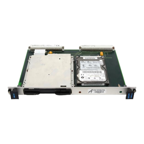
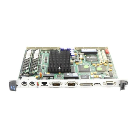
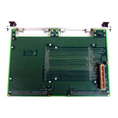
Xycom XVME-601 User manual

Artisan Technology Group is your source for quality
new and certied-used/pre-owned equipment
• FAST SHIPPING AND
DELIVERY
• TENS OF THOUSANDS OF
IN-STOCK ITEMS
• EQUIPMENT DEMOS
• HUNDREDS OF
MANUFACTURERS
SUPPORTED
• LEASING/MONTHLY
RENTALS
• ITAR CERTIFIED
SECURE ASSET SOLUTIONS
SERVICE CENTER REPAIRS
Experienced engineers and technicians on staff
at our full-service, in-house repair center
WE BUY USED EQUIPMENT
Sell your excess, underutilized, and idle used equipment
We also offer credit for buy-backs and trade-ins
www.artisantg.com/WeBuyEquipment
REMOTE INSPECTION
Remotely inspect equipment before purchasing with
our interactive website at www.instraview.com
LOOKING FOR MORE INFORMATION?
Visit us on the web at www.artisantg.com for more
information on price quotations, drivers, technical
specications, manuals, and documentation
Contact us: (888) 88-SOURCE | sales@artisantg.com | www.artisantg.com
SM
View
Instra

0
1993
XYCOM,INC.
Printed
in
theUnited States
of
America
Part
Number
74601-001
B
6800016801
0
Processor Module
74601-001
B
XYCOM
750 North Maple Road
Saline,Michigan 48176-1292
734-429-4971 (phone)
734-429-1010
(fa)
Artisan Technology Group - Quality Instrumentation ... Guaranteed | (888) 88-SOURCE | www.artisantg.com

XYCOM REVISION RECORD
~
Revision Description
A
B
ManualReleased
IncorporatedPCN
120
Date
12/86
06/93
Copyright
Information
This
document
is
copyrightedbyXycomIncorporated(Xycom)andshallnotbereproducedorcopiedwithout
expressedwrittenpermission
from
Xycom.
Theinformationcontainedwithinthisdocument
is
subjecttochangewithoutnotice. Xycomdoesnotguarantee
the accuracy
of
the
informationandmakes no commitmenttowardkeeping
it
up to date.
Address commentsconcerning
this manual to:
TechnicalPublicationsDept.
fr:MmleRoad
Saline,Michigan
48176
Part
Number:
74601
-001
B
Artisan Technology Group - Quality Instrumentation ... Guaranteed | (888) 88-SOURCE | www.artisantg.com

XVME-601 Manual
December, 1986
'-
'
TABLE OF CONTENTS
.:.
CHAPTER
1
1.1
1.2
1.3
1.3.1
1.3.2
1.3.3
1.3.4
1.3.5
1.3.6
1.4
2
2.1
2.2
2.3
2.4
2.4.1
2.4.2
2.4.3
2.4.4
2.4.5
2.5
2.6
2.7
2.8
2.9
3
3.1
3.2
3.2.1
3.3
3.4
3.5
TITLE PAGE
MODULE DESCRIPTION
Introduction 1-1
Manual Structure 1-2
Modu
1
e
0
perationa
1
Description 1-2
VMEbus Master Interface 1-4
The 68681 Dual Universal Asynchronous Receiver
/Transmitter 1-4
Interrupts 1-5
Status LEDs and Control Switches 1-6
System Resource Functions 1-6
Local DRAM 1-6
XVME-601 Processor Module Specifications 1-7
XVME-601 INSTALLATION
Introduction
Location of Components Relevant to Installation
Jumpers
Jumper Descriptions
RESET/ABORT Switch Enable Jumpers
System Resource Function Jumpers
EPROM/RAM Type Selection Jumpers
VMEbus Interrupt Level Selection Jumpers
Bus Grant and Bus Request Level
Selection Jumpers
Installing EPROM on the XVME-601 Processor
Module
External Connector JK1
Module Installation
Installing the XVME-990/2 Monitor/RAM Kit
Installing a 6U Front Panel Kit
2-1
2-1
2-3
2-3
2-4
2-5
2-7
2-7
2-8
2-8
2-1
1
2-12
2-14
2-16
PROGRAMMING
Introduction 3-1
The XVME-601 Processor Module Memory Map 3-1
The 68681 DUART Memory Map 3-3
Using the 68681
1/0
Ports 3-5
68681 DUART Initialization
3-7
Interrupts 3-8
1
Artisan Technology Group - Quality Instrumentation ... Guaranteed | (888) 88-SOURCE | www.artisantg.com

XVME-60
1
Manual
December,
1986
TABLE
OF
CONTENTS continued
CHAPTER
4
4.1
4.2
4.3
4.3.1
4.3.1.1
4.3.2
4.4
4.4.1
4.4.2
4.4.3
4.4.4
4.5
4.6
4.6.1
4.6.2
4.6.3
4.6.4
4.6.5
4.6.6
4.6.7
4.6.8
4.6.9
4.6.10
4.6.1 1
4.6.12
4.6.1 3
4.6.14
4.6.15
4.6.16
4.6.17
4.6.18
4.6.19
4.6.20
4.6.2
1
4.6.22
4.6.23
4.6.24
4.6.25
4.6.26
4.7
TITLE
XV
ME
-
6
0
0
MON
Introduction
Referenced Documents
System Configuration
600MON
Memory Map
Exception Vectors
6OOMon
1/0
Using 600MON
Expression Parameters
Address Parameters
Offset Registers
Data Parameters
Command Verification
Command Set
Display/Set Register
Block Fill
Block Initialize
Block Move
Breakpoint Set and Remove
Block of Memory Search
Block of Memory Test
Data Conversion
Display Formatted Registers
Dump Memory (S-Records)
Execute Programs
Go Direct Execute Program
Go Until Breakpoint
Help
Load (S-Records)
Memory Display
/
D
i
s
a
ss
e
m
b
1
e
Memory Modify/Disa
s
s
emb
1
e Assemb
1
e
Memory Set
Display Offsets
Port Attach and Detach
Port Format
Register Modify
Transparent Mode
Trace
Trace to Temporary Breakpoint
Verify (S-Records)
Using
600MON
1/0
Routines Through Trap
15
PAGE
4-1
4-1
4-2
4-3
4-5
4-5
4-5
4-6
4-7
4-8
4-9
4-10
4-1
1
4-12
4-13
4-14
4-15
4-16
4-18
4-19
4-20
4-21
4-22
4-23
4-25
4-26
4-27
4-28
4-29
4-3
1
4-33
4-34
4-35
4-36
4-37
4-38
4-39
4-41
4-42
4-43
..
11
Artisan Technology Group - Quality Instrumentation ... Guaranteed | (888) 88-SOURCE | www.artisantg.com

XVME-601 Manual
December, 1986
TABLE OF CONTENTS continued
CHAPTER TITLE
APPENDICES
PAGE
VMEbus Connector/Pin Description
Block Diagram, Assembly Drawing, and Schematics
Quick Reference Guide
A
B
C
LIST OF FIGURES
TITLE PAGE
FIGURE
1-1 Module Operational Block Diagram 1-3
Location of Jumpers, Sockets, and Connectors
XVME-60
1
Memory Map (Factory-Shipped
Configuration) 2-10
Connector JK1 2-11
Memory Map after Installing XVME-990 Monitor/
RAM Kit 2-15
Installation of an XVME-943 Front Panel 2-17
2-2
2-1
2-2
2-3
2-4
2-5
XVME-601 Processor Module Memory Map 3-2
68681 DUART Memory Map 3-4
3-1
3-2
4-
1
4-2 Typical XVME-60
1
System Configuration
600MON Memory Map 4-2
4-4
LIST OF TABLES
TABLE TITLE PAGE
1-1 XVME-601 Processor Module Specifications 1-7
2-
1
2-2
2-3
2-4
2-5
2-6
Jumper List
RESET/ABORT
System Resource Function Jumpers
EPROM Selection Jumpers for Sockets U30
&
U29
Interrupt Selection Jumpers
Bus Grant and Bus Request Level Selection
Jumpers
"Local" RAM/PROM Memory Configurations
Connector JK1 Pin Designations
2-3
2-4
2-6
2-7
2-6
2-8
2-9
2-12
2-7
2-8
3-1
3-2 68681 Parallel Input Status Indications
68681 Output Control Functions 3-5
3-6
...
111
Artisan Technology Group - Quality Instrumentation ... Guaranteed | (888) 88-SOURCE | www.artisantg.com

XVME-60
1
Manual
December,
1986
LIST OF TABLES continued
TABLE TITLE
3-3
XVME-601 Processor Module Interrupts
4-
1
Off
set Examples
4-2
600MON Commands
4-3
Available User Routines
4-4
Registers Used by Function
PAGE
3-8
4-8
4-1
1
4-44
4-45
iv
Artisan Technology Group - Quality Instrumentation ... Guaranteed | (888) 88-SOURCE | www.artisantg.com

XVME-601 Manual
December, 1986
Chapter
1
MODULE DESCRIPTION
1.1
INTRODUCTION
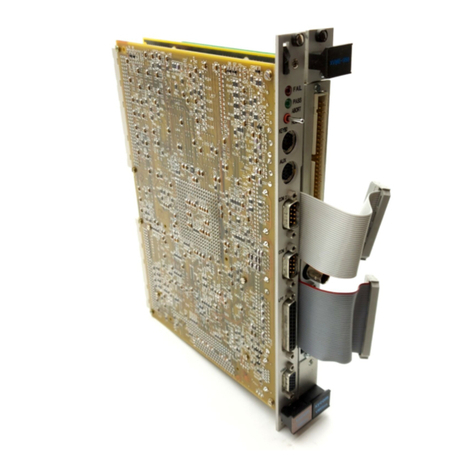
The XVME-601 Processor Module is a single-high, VMEbus compatible board, which
uses a 68000 or 68010 CPU running at 10 MHz. The module'contains two byte-wide
memory sockets for EPROM devices. These sockets allow a maximum of 128K bytes
of EPROM to be installed. On board DRAM chips provide 512K bytes of local RAM.
The CPU is capable of accessing the local DRAM and EPROM without the need for
"wait states". XYCOM's XVME-990/2 600MON Debugger Kit is available for the
XVME-60 1.
The XVME-601 Processor Module provides two RS-232 serial ports, and a 16-bit
programmable timer via an on-board 6868
1
Dual Asynchronous Receiver/Transmitter
(DUART). The module also incorporates three front panel LEDs to indicate
diagnostic PASS/FAIL status (diagnostics are included in the 601 monitor), as well
as CPU HALT status.
In addition, the XVME-601 Processor Module provides all of the VMEbus utilities
required for a complete system, including:
0
SYSCLK
0
SYSRESET
0
A single level arbiter
0
A
Bus
Timer
0
IACK Daisy Chain Driver
The XVME-601 Processor is specified as an A24/A16:D16/D08 (EO) VMEbus Master,
and as an IH(0)-IH(7)interrupt handler.
1-1
-
Artisan Technology Group - Quality Instrumentation ... Guaranteed | (888) 88-SOURCE | www.artisantg.com

XVME-601 Manual
December, 1986
1.2
MANUAL STRUCTURE
It is the aim of this first chapter to introduce the user to the general
specifications and functional capabilities of the XVME-601 Processor Module.
Successive chapters will develop the various aspects of module specification and
operation in the following progression:
ChaDter One
-
A general description of the XVME-601 Module, including
complete functional and environmental specifications, VMEbus compliance
information, and a detailed block diagram.
Chapter Two
-
Module installation information, covering jumpers and connector
pinouts.
Chapter Three
-
Includes information on the module memory map, the 68681
DUART (including a DUART initialization program), and the interrupt structure.
Chapter Four
-
Contains information on the operation and use of the optional
600MON debug monitor.
The appendices at the rear of this manual are designed
to
introduce and reinforce a
variety
of
module related topics inc1uding:backplane signal/pin
descriptions, a block diagram and schematics, and a quick reference section.
NOTE
In order to fully document the complex versatility of the
XVME-601 and the 68681 DUART device, a manual kit is being
shipped with the XVME-601 Module (the manual kit is
referenced as XYCOM Part #74601-001). This kit consists of
two parts: a *Motorola 68681 Manual (referenced as XYCOM
part
#
74601-003), and this document, the XVME-601 Processor
Module Manual (referenced as XYCOM Part #74601-002).
The 68681 Manual covers all information on the operation lay-
out, and programming of the DUART. The XVME-601 Manual covers
module hardware specifics, register access addresses, and
operational programming constraints.
*
MC6868
1
Dual Asynchronous Receiver/Transmitter Manual,
Motorola Inc.
1985
1.3
MODULE OPERATIONAL DESCRIPTION
Figure 1-1 shows an operational block diagram of the XVME-601 Processor Module.
1-2
Artisan Technology Group - Quality Instrumentation ... Guaranteed | (888) 88-SOURCE | www.artisantg.com

XVME-60
1
Manual
December,
1986
68000
OR
68010
REFRESH
CONTROLLER
VME
MASTER
INTERFACE
INTERRUPT
HANDLER
INTERFACE
INTERRUPTER
E
SWITCES
STATUS LEDs
RS232 PORT A
RS232 PORT
B
SYSllEM
RESOURCE
FUNCTIONS
I
1
*PROM Comes with the XVME-990/2 Monitor Debugger Kit.
Figure
1-1.
Module Operational
Block
Diagram
1-3
Artisan Technology Group - Quality Instrumentation ... Guaranteed | (888) 88-SOURCE | www.artisantg.com

XVME-601 Manual
December, 1986
1.3.1 VMEbus Master Interface
The VME master interface on the XVME-601 Processor Module supports the
following bus cycles:
0
A24
(Address Modifier Codes 39H, 3AH, 3DH, or 3EH)
0
A16 (Address Modifier Codes 29H, 2DH)
0
D16
0
D8 (Even or Odd Transfers)
0
Read-Modify-Write (RMW) Cycles
-
D8
(Even or Odd Transfers)
0
Interrupt Acknowledge Cycles
-
D8 (Odd Transfers Only)
Note that RMW cycles can use either even or odd byte transfers, while IACK cycles
can use only odd byte transfers. The XVME-601 Module can be configured (Via
Jumpers) to use any of the four bus arbitration levels (see Chapter 2).
The VMEbus is requested when the CPU executes an off-board memory or IACK
cycle, and the XVME-601 Module does not presently have control of the bus. After
requesting the bus, wait cycles will be inserted until the bus is acquired and the
slave response with DTACK* or BERR". When the module has control of the
VMEbus, the wait states due to the acquisition phase will cease.
The bus release mechanism may be Release When Done (RWD), Release On Request
(ROR), release on BCLR* (ROBC), or release on ACFAIL* (ROACF). In the last
case an interrupt can be generated when ACFAIL* is asserted, and the CPU can
release the bus if desired. Early BBSY* release is supported when the XVME-601
Module decides to release the bus during the last master cycle.
1
1.3.2 The
68681
Dual Universal Asynchronous Receiver Transmitter (DUART)
A 68681 DUART is used to provide two RS-232 serial communication channels, a 16-
bit timer, and two ports dedicated to module status and control I/O. The two
asynchronous serial channels (labeled Channel A and Channel B are configured as
RS-232 Data Communication Equipment (DCE) channels. Independent baud rate
generators allow most of the popular data rates from
75
to 19.2K baud. In addition
to the standard receive and transmit lines, Channel A has a modem control input
(RTS) and output (CTS). All serial communication lines are accessible at the 26 pin
connector (labeled
JK1)
located on the module front panel (refer to Chapter 2 for
the Channel A and B pinouts).
1-4
Artisan Technology Group - Quality Instrumentation ... Guaranteed | (888) 88-SOURCE | www.artisantg.com

XVME-601 Manual
December, 1986
The 68681 contains a timer/counter which is independent from the serial channel
baud rate generators. The timer can be programmed from the serial channel baud
rate generators. The timer can be programmed from the serial channel baud rate
generators. The timer is set up to use 3.6864 MHz/l6 or 230.4 KHz as its time
base. This will allow periodic interrupts or square wave outputs ranging from
17.4uS to 569mS (refer to the MC68681 Dual Asynchronous Receiver/Transmitter
Manual for information on programming the timer).
The 68681 DUART on the XVME-601 Processor Module is configured to provide 6
parallel inputs and 8 parallel outputs. These
1/0
points are used by the CPU to
control and monitor a variety of module functions. The input lines are used by the
CPU to monitor the following:
-
the RTS line on Channel A
-
when the module has control of the VMEbus
-
SYSFAIL*, BCLR*, and ACFAIL" lines
-
the ABORT button on the front panel
The output lines are used by the CPU to control the following functions:
-
the Channel
A
CTS
output
-
the type of bus release mechanism to be used by the module
-
the PASS and FAIL LEDs on the module front panel
-
clearing and enabling interrupts
1.3.3
Interrupts
The Processor on the XVME-601 Processor Module can be interrupted via all seven
VMEbus interrupts, plus 2 local and 2 special interrupt sources. The local interrupt
sources include the ABORT push-button, and the 68681 DUART, and the special
interrupts include ACFAIL* and SYSFAIL*. Note that ACFAIL* and SYSFAIL* are
considered special interrupts in this case because they must be individually enabled
by the CPU through the 68681 outputs. Refer to 68681 Manual for information on
the types of interrupts which the DUART itself can generate.
One of the outputs on the 68681 DUART is used to enable/disable all interrupt
capability, and some are used to individually enable/clear local and special interrupt
capabilities. Refer to Section 3.3 for information on controlling the 68681 outputs.
The local interrupts have priority over the VMEbus interrupts when both exist on
the same level.
1-5
Artisan Technology Group - Quality Instrumentation ... Guaranteed | (888) 88-SOURCE | www.artisantg.com

XVME-601 Manual
December, 1986
1.3.4 Status
LEDs
and Control Switches
Two momentary push-button switches can be found on the front panel of the
module, they are labeled RESET and ABORT. RESET will reset the module and the
VMEbus (via SYSRESET*). The DRAM refresh logic is not disabled during reset,
therefore the module may be reset without effecting the contents of the DRAM.
ABORT generates a level
7
interrupt to the CPU.
In addition, three LEDs can be found on the module front panel. The LEDs are
labeled FAIL, PASS, and HALT. Fail is on when the CPU is asserting SYSFAIL*.
The PASS light is controlled directly by the CPU. HALT is on when the CPU
enters halt state.
1.3.5 System Resource Functions
The following system resource functions exist on the XVME-601 Processor Module:
0
SYSCLK driver
0
SYSRESET driver
0
IACK daisy-chain driver
0
Single-level arbiter
0
Bus’timeout
The system resource functions can be enabled/disabled via jumpers (refer to Chapter
2).
The Module is shipped from the factory with the system resource functions
enabled.
1.3.6 Local
DRAM
On board DRAM provides
512K
of random access memory.
No
wait states are
required to access the DRAM except when the CPU tries to access the DRAM
during a refresh cycle.
A
refresh cycle requires 3 clock periods (300nS). Therefore
the maximum number of wait states will be
3.
No
wait states will be encountered
during a refresh cycle when the CPU accesses anything other than the DRAM. The
ram exists from address OOOOOOH through 07FFFFH. The refresh circuitry is not
disabled during the reset, therefore the module may be reset with out effecting the
contents.
1-6
Artisan Technology Group - Quality Instrumentation ... Guaranteed | (888) 88-SOURCE | www.artisantg.com

XVME-601 Manual
December, 1986
1.4
XVME-601 PROCESSOR MODULE SPECIFICATIONS
Table 1-1 is a list of the operational and environmental specifications for the
XVME-601 Processor Module.
Table 1
-
1. XVME-601 Processor Module Specifications
Characteristic
Processor
Speed
Memory Capacity
EPROM
DRAM
Serial Ports
Number
Compatibility
Baud Rates
Signals
Time Base Generator
Front Panel Indicators
Front Panel Switches
Power Requirements
Temperature
Operating
Non-operating
Humidity
Altitude
Operating
Non-operating
Specifications
68000 or 68010
10
MHz
2 sockets or up to 128K bytes
512K bytes
2
75
-
19.2K baud, programmable
Port A
-
TxD, RxD, RTS, CTS
Port B
-
TxD, RxD
RS-232
17.4uSec to 569mSec.
FAIL (red), PASS (green), and
HALT (red)
RESET and ABORT
+5 volts
@
2.8A Max. (2.5 A
+/-
12 volts
@
lOOmA Max.
(1OmA Typ.)
TYP.1
0
to 65 C (32 to 149 F)
-40
to 85 C (-40 to 158 F)
5 to 95% RH non-condensing
(Extremely low humidity may
require protection against static
discharge
.)
Sea-level to 10,000 ft. (3048m)
Sea-level to
50,000
ft. (15240m)
-7
Artisan Technology Group - Quality Instrumentation ... Guaranteed | (888) 88-SOURCE | www.artisantg.com

XVME-601 Manual
December, 1986
Table 1-1. XVME-601 Processor Module Specifications cont.
I
Characteristic
Vibration
Operating
Non-operating
Shock
Operating
Non-operating
VMEbus Compliance
Specifications
5 to 2000
Hz
.015 in. peak-to-peak
2.5g max.
5 to
2000
Hz
.030
in. peak-to-peak
5.0g max.
30 g peak acceleration
11 mSec duration
50 g peak acceleration
11 mSec duration
0
A24/A 16:D16/D08(EO) DTB
0
RMW Capability
Master
IH(l)-IH(7) D08(0
Interrupt Handler
0
SGL Arbiter
0
R(0-3) Bus Requester
0
bus release
0
ROACF (software
contr
o
11
ed) bus re
1
ease
0
BTO (16,32,64,128)STAT
0
IDCD IACK Daisy Chain
0
SYSCLK and SYSRESET
0
Monitors SYSFAIL,
0
RWD, ROR,or ROBC (DYN
driver
driver
ACFAIL, and BCLR
SINGLE
-
3U
Form Factor
1-8
Artisan Technology Group - Quality Instrumentation ... Guaranteed | (888) 88-SOURCE | www.artisantg.com

XVME-601 Manual
December, 1986
Chapter 2
XVME-60
1
INSTALLATI
ON
2.1
INTRODUCTION
This chapter provides the information needed to configure and install the XVME-601
Processor Module.
2.2
LOCATION
OF
COMPONENTS RELEVANT TO INSTALLATION
The jumpers, PROM sockets, and connectors on the XVME-601 Processor Module are
illustrated in Figure 2-1.
2-1
Artisan Technology Group - Quality Instrumentation ... Guaranteed | (888) 88-SOURCE | www.artisantg.com

XVME-601 Manual
December, 1986
1
7
J2
D
AB
J10Jl;l2\\\\
\
Figure 2-1. Location
of
Jumpers, Sockets, and Connectors.
2-2
Artisan Technology Group - Quality Instrumentation ... Guaranteed | (888) 88-SOURCE | www.artisantg.com

XVME-60
1
Manual
December, 1986
2.3
JUMPERS
Prior to installing the XVME-601 Processor Module, it will be necessary to
configure several jumper options. The configuration of the jumpers is dependant
upon which of the module capabilities are required for a given application, and the
type of PROM used for "local" memory. The following table shows a list of the
jumpers and a brief description of their use.
Table 2-1. Jumper List
XVME-601 Jumpers
Jumper
J1
J3,J4,J5,J6,J7,
and 517
J2,J8
J9,10,11,12,13,14,15
J16
J18,J19,
&
520
This jumper is used to enable/disable the reset switch on
the front panel of the module.
These jumpers are used to enable/disable the system
resource functions
These jumpers are configured to match the type and size
of EPROM which is installed on the XVME-601.
These jumpers are used to determine which VMEbus
interrupt levels (1-7) can be used to interrupt the CPU
This jumper enables/disables the abort switch on the front
panel of the module.
These jumpers are used to select the bus request and bus
grant levels.
2.4
JUMPER DESCRIPTIONS
Each of the following subsections examines the jumper options in closer detail,
showing specifically when and how jumpers should be configured.
2-3
Artisan Technology Group - Quality Instrumentation ... Guaranteed | (888) 88-SOURCE | www.artisantg.com

XVME-601 Manual
December, 1986
Jumper J1
In
out
2.4.1
RESET/ABORT
Switch
Ena,.z
Jumpers
(J
Jumper
J
16 RESET Switch ABORT Switch
Enabled
Disabled
In Enabled
out Disabled
&
516)
There are two momentary push-button switches which can be found on the front
panel of the module. The switches are labeled RESET and ABORT. When the
RESET button is enabled (by installing jumper Jl), it can be used to reset the CPU
and the VMEbus. When the ABORT button
is
enabled (by installing jumper J16), it
can be used to generate a level
7
interrupt to the CPU. Table 2-2 shows the
configuration of these jumpers for enabling/disabling the front panel switches.
The XVME-601 Module is configured at the factory with both RESET and ABORT
activated.
NOTE
Use of the RESET button activates the SYSRESET" line
if jumpers J1 and J6 are installed, thereby resetting
the entire backplane. The RESET button cannot be used
to just reset the XVME-601 board.
2-4
Artisan Technology Group - Quality Instrumentation ... Guaranteed | (888) 88-SOURCE | www.artisantg.com

XVME-60
1
Manual
December,
1986
2.4.2
System Resource Function Jumpers (J3,54,55,56,57)
The XVME-601 Processor Module provides all of the VMEbus utilities required for
a
complete system, including:
0
SYSCLK
0
SYSRESET
0
A
single level arbiter
0
A
Bus Timer
NOTE
For the most part, the system resource functions
are employed as a group (i.e. either they are all
enabled, or they are all disabled). However, the
SYSRESET function can be used by itself as long as
jumpers
J1
and J6 are installed.
The following are the definitions of the system resource jumpers:
2-5
Artisan Technology Group - Quality Instrumentation ... Guaranteed | (888) 88-SOURCE | www.artisantg.com
Table of contents
Other Xycom Control Unit manuals

Xycom
Xycom XVME-678 User manual

Xycom
Xycom XVME-678 User manual

Xycom
Xycom XVME-976/202 User manual

Xycom
Xycom XVME-682 User manual

Xycom
Xycom XVME-956 Series User manual

Xycom
Xycom XVME-212 User manual

Xycom
Xycom XVME-951 User manual

Xycom
Xycom XVME-653 User manual

Xycom
Xycom XVME-654 User manual

Xycom
Xycom XVME-977 User manual