Xycom 3700 Series User manual

Artisan Technology Group is your source for quality
new and certied-used/pre-owned equipment
• FAST SHIPPING AND
DELIVERY
• TENS OF THOUSANDS OF
IN-STOCK ITEMS
• EQUIPMENT DEMOS
• HUNDREDS OF
MANUFACTURERS
SUPPORTED
• LEASING/MONTHLY
RENTALS
• ITAR CERTIFIED
SECURE ASSET SOLUTIONS
SERVICE CENTER REPAIRS
Experienced engineers and technicians on staff
at our full-service, in-house repair center
WE BUY USED EQUIPMENT
Sell your excess, underutilized, and idle used equipment
We also offer credit for buy-backs and trade-ins
www.artisantg.com/WeBuyEquipment
REMOTE INSPECTION
Remotely inspect equipment before purchasing with
our interactive website at www.instraview.com
LOOKING FOR MORE INFORMATION?
Visit us on the web at www.artisantg.com for more
information on price quotations, drivers, technical
specications, manuals, and documentation
Contact us: (888) 88-SOURCE | sales@artisantg.com | www.artisantg.com
SM
View
Instra

2007 XYCOM AUTOMATION, LLC. Printed in the United States of America
3700 Series
Flat-Panel Industrial PCs
User Manual for the
3712KPM, 3712KPMT,
3715T, 3715KPM, & 3715KPMT
Models
Artisan Technology Group - Quality Instrumentation ... Guaranteed | (888) 88-SOURCE | www.artisantg.com

3700 Series Flat Panel Industrial PC Revision Record
143311 (H)
Revision Description Date
A Manual Released 01/04
B Added 3712 series information, keypad inserts, updated kp3util 03/04
C Updated touch screen driver installation and calibration / 05/04
Added TIR caution 06/04
D Clarified front panel frame, glass and overlay in Tables 1-1 & 1-2 08/04
E Updated 3712KPM(T) available power specifications/ Added 09/04
24V DC power supply information
F RAID-Enabled Appendix added 10/04
G Added System Battery Replacement section 01/06
H Name change, correct where applicable with document 4/07
Part Number 143311 (H)
Trademark Information
Xycom and Xycom Automation are trademarks of Xycom Automation, L.L.C.
Xycom Automation, L.L.C. now is referred to as Pro-face through a D.B.A. The Pro-face name and logo will replace
the Xycom name and logo on all documents where possible.
Pro-face is a trademark of Digital Electronics Corporation.
Brand or product names are trademarks or registered trademarks of their respective owners.
Intel and Pentium are registered trademarks and Celeron is a trademark of Intel Corporation.
Windows, Windows NT, and Windows XP are registered trademarks of Microsoft Corporation in the U.S. and in
other countries.
Copyright Information
This document is copyrighted by Xycom Automation, L.L.C. (Xycom) and shall not be reproduced or copied without
expressed written authorization from Xycom Automation, L.L.C.
The information contained within this document is subject to change without notice. Pro-face does not guarantee the
accuracy of the information
United States FCC Part 15, Subpart B, Class A EMI Compliance Statement:
NOTE: This equipment has been tested and found to comply with the limits for a Class A digital device, pursuant to
part 15 of the FCC Rules. These limits are designed to provide reasonable protection against harmful interference
when the equipment is operated in a commercial environment. This equipment generates, uses, and can radiate
radio frequency energy and, if not installed and used in accordance with the instruction manual, may cause harmful
interference to radio communications. Operation of this equipment in a residential area is likely to cause harmful
interference in which case the user will be required to correct the interference at the user’s expense.
For European Users – WARNING:
This is a Class A product. In a domestic environment this product may cause radio interference in which case the
user may be required to take adequate measures.
INSTALLATION – Electromagnetic Compatibility WARNING:
The connection of non-shielded equipment interface cables to this equipment will invalidate FCC EMI and European
Union EMC compliance and may result in electromagnetic interference and/or susceptibility levels which are in
violation of regulations applying to the legal operation of this device. It is the responsibility of the system integrator
and/or user to apply the following directions relating to installation and configuration:
All interface cables must include shielded cables. Braid/foil type shields are recommended. Communication cable
connectors must be metal, ideally zinc die-cast backshell types, and provide 360-degree protection about the
interface wires. The cable shield braid must be terminated directly to the metal connector shell; ground drain wires
alone are not adequate.
Protective measures for power and interface cables as described within this manual must be applied. Do not leave
cables connected to unused interfaces or disconnected at one end. Changes or modifications to this device not
expressly approved by the manufacturer could void the user’s authority to operate the equipment.
Artisan Technology Group - Quality Instrumentation ... Guaranteed | (888) 88-SOURCE | www.artisantg.com

Chapter Two - Testing
ii 143311 (H)
EMC compliance is, in part, a function of PCB design. Third party add-on AT/XT peripheral PCB assemblies installed
within this apparatus may void EMC compliance. FCC/CE compliant PCB assemblies should always be used where
possible. Pro-face can accept no responsibility for the EMC performance of this apparatus after system
integrator/user installation of PCB assemblies not manufactured and/or expressly tested and approved for
compliance by Pro-face. It is the responsibility of the system integrator/user to ensure that installation and operation
of such devices does not void EMC compliance.
Artisan Technology Group - Quality Instrumentation ... Guaranteed | (888) 88-SOURCE | www.artisantg.com

i 143311 (H)
Table of Contents
CHAPTER 1 – INTRODUCTION .................................................................................................................................1
PRODUCT OVERVIEW ..................................................................................................................................................1
STANDARD FEATURES .................................................................................................................................................1
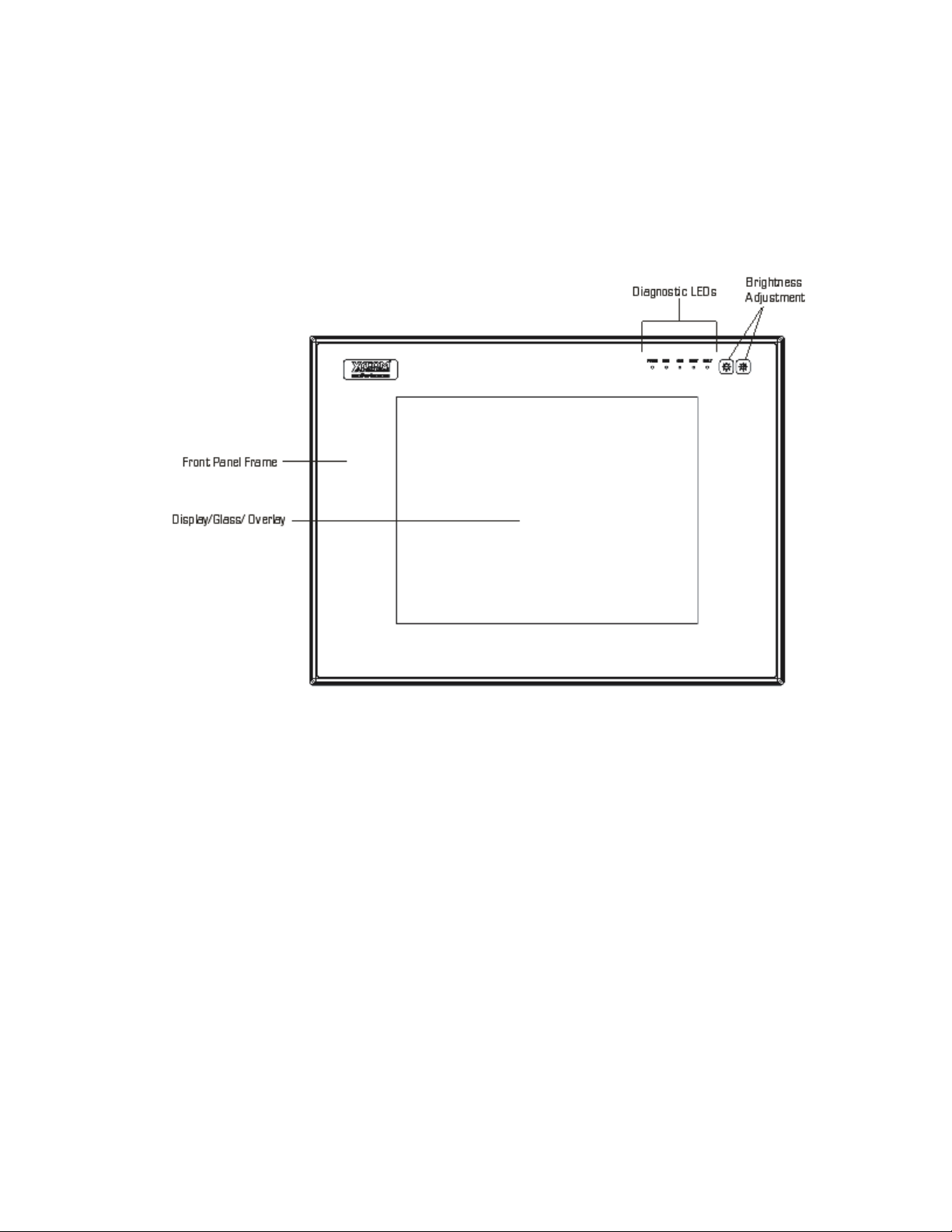
Front Panels.........................................................................................................................................................3
I/O Panel ..............................................................................................................................................................7
Back Panel...........................................................................................................................................................9
Power Panel.......................................................................................................................................................10
UNPACKING THE SYSTEM ...........................................................................................................................................11
QUICK STARTUP .......................................................................................................................................................11
CHAPTER 2 – INSTALLATION.................................................................................................................................12
INSTALLATION OVERVIEW...........................................................................................................................................12
SYSTEM CUTOUT DIMENSIONS....................................................................................................................................14
3712kpm(t).........................................................................................................................................................14
3715T& 3715KPM(T)...........................................................................................................................................15
POWER MANAGEMENT...............................................................................................................................................16
System Power....................................................................................................................................................16
Excessive Heat ..................................................................................................................................................17
Electrical Noise ..................................................................................................................................................17
Line Voltage Variation........................................................................................................................................18
AC Power Cable ................................................................................................................................................18
INSTALLING INTERNAL HARDWARE OPTIONS ................................................................................................................19
DRAM and Additional DRAM Dual Inline Memory Modules (DIMMs) ................................................................20
PC/AT™and PCI Boards....................................................................................................................................20
USING A TOUCH SCREEN ...........................................................................................................................................20
Installing the Touch Screen Driver.....................................................................................................................21
Calibrating the Touch Screen ............................................................................................................................22
CUSTOM LOGO .........................................................................................................................................................23
CREATING CUSTOM KEYPAD INSERTS .........................................................................................................................23
HAZARDOUS LOCATIONS INSTALLATION .......................................................................................................................29
Safety Agency Approval.....................................................................................................................................29
Definitions ..........................................................................................................................................................31
Class I Locations................................................................................................................................................31
Class II Locations...............................................................................................................................................31
Division 1 Locations...........................................................................................................................................31
Division 2 Locations...........................................................................................................................................31
Groups ...............................................................................................................................................................32
Enclosures .........................................................................................................................................................32
Power Switch .....................................................................................................................................................33
Cable Connections.............................................................................................................................................33
Communication Cable Interfaces.......................................................................................................................33
Hazardous Locations Control Drawing...............................................................................................................34
Operation and Maintenance...............................................................................................................................35
CHAPTER 3 – KEYPAD UTILITY PROGRAM..........................................................................................................36
LOADING THE KEYPAD UTILITY....................................................................................................................................36
USING THE KEYPAD UTILITY .......................................................................................................................................36
STARTUP .................................................................................................................................................................37
MAIN MENU ..............................................................................................................................................................37
Exit .....................................................................................................................................................................38
Files Menu .........................................................................................................................................................38
Macros Menu .....................................................................................................................................................39
Upload Menu......................................................................................................................................................41
Download Menu .................................................................................................................................................41
Utilities Menu .....................................................................................................................................................42
UTILITY BATCH MODE ................................................................................................................................................42
KEYPAD SCAN CODES ...............................................................................................................................................43
Artisan Technology Group - Quality Instrumentation ... Guaranteed | (888) 88-SOURCE | www.artisantg.com

3700 Series Flat Panel Industrial PC Table of Contents
ii 143311 (H)
CHAPTER 4 – MAINTENANCE ................................................................................................................................46
GENERAL PREVENTIVE MAINTENANCE.........................................................................................................................46
Fuse Replacement.............................................................................................................................................46
Fan Filter Replacement......................................................................................................................................47
RECOMMENDED HARD DRIVE PREVENTIVE MAINTENANCE .............................................................................................47
SYSTEM BATTERY REPLACEMENT ...............................................................................................................................48
PRODUCT REPAIR PROGRAM......................................................................................................................................51
3700 FRONT PANEL FRAME.......................................................................................................................................53
Chemicals Compatible with 3700 Frame ...........................................................................................................53
Front Panel Overlay ...........................................................................................................................................54
Chemicals Compatible with Overlay ..................................................................................................................54
Compatible Cleaning Agents for Overlay...........................................................................................................54
Chemicals Not Compatible with Overlay............................................................................................................54
CHAPTER 5 – TROUBLESHOOTING.......................................................................................................................55
DIAGNOSTIC TESTING ................................................................................................................................................55
Create Diagnostic Disk ......................................................................................................................................55
Prepare the System ...........................................................................................................................................55
RUNNING THE TESTS .................................................................................................................................................57
REINSTALLING OPERATING SYSTEMS ..........................................................................................................................58
MS-DOS
Reinstallation ....................................................................................................................................58
Windows
98 Reinstallation ..............................................................................................................................58
Windows
2000 Reinstallation ..........................................................................................................................59
Windows NT
Reinstallation .............................................................................................................................59
Windows XP® Reinstallation .............................................................................................................................59
INSTALLING DRIVERS .................................................................................................................................................60
Video Drivers .....................................................................................................................................................60
Video Expansion ................................................................................................................................................60
Touch Screen Drivers ........................................................................................................................................61
Miscellaneous Drivers........................................................................................................................................61
APPENDIX A – TECHNICAL SPECIFICATIONS......................................................................................................62
HARDWARE SPECIFICATIONS ......................................................................................................................................62
ENVIRONMENTAL SPECIFICATIONS ..............................................................................................................................63
APPENDIX B – BLOCK DIAGRAM AND AIM3 LAYOUT.........................................................................................64
AC MODEL BLOCK DIAGRAM......................................................................................................................................64
AIM3 CPU BOARD LAYOUT.......................................................................................................................................65
APPENDIX C – PINOUTS .........................................................................................................................................66
KEYBOARD PORT CONNECTOR ...................................................................................................................................66
MOUSE PORT CONNECTOR ........................................................................................................................................66
DUAL USB CONNECTOR (USB1) ...............................................................................................................................67
PARALLEL PORT CONNECTOR (LPT1).........................................................................................................................67
SERIAL PORT CONNECTORS.......................................................................................................................................68
COM1.....................................................................................................................................................................68
COM2.....................................................................................................................................................................69
VGA CONNECTOR ....................................................................................................................................................69
APPENDIX D – AIM3 CONTROLLER JUMPERS.....................................................................................................70
APPENDIX E – TSKAM SETTINGS..........................................................................................................................71
APPENDIX F – THE RAID-ENABLED IPC OPTION.................................................................................................72
Artisan Technology Group - Quality Instrumentation ... Guaranteed | (888) 88-SOURCE | www.artisantg.com

1 143311 (H)
Chapter 1 – Introduction
Product Overview
The 3700 series of Flat Panel Industrial Computers combines an Intel®Celeron®or
Pentium®III processor with a flat-panel display to offer a powerful, compact
package for the factory floor and other harsh environments. The PC features an
open architecture to meet a wide variety of applications that require both a
powerful PC and a durable industrial enclosure. The system integrates a computer
card cage, mass storage, display, and power supply in a reliable industrial form
factor.
The 3715T is an industrial PC with touch screen display. The 3712KPM and
3715KPM are industrial PCs, which contain a display, an integrated keypad and an
integrated mouse. The 3712KPMT and 3715KPMT are industrial PCs, which
contain an integrated keypad, an integrated mouse, and a touch screen display.
The front panels of the 3700 units are sealed to NEMA TYPE 4/4X/12 (UL 50)
and IP65 (IEC 60529) standards and are protected by an impact-resistant shield.
The processor board combines all the functions of a complete PC/AT compatible
computer on a single industrially-hardened circuit board. Refer to the AIM3 CPU
manual for more information on processor and hardware features.
The system’s modular design allows easy access to expansion boards, switches,
power supply, flat-panel display, and disk drives.
Standard Features
The 3700 unit comes standard with the following:
•
••
•
AIM3 CPU Board
• Two serial COM ports, with one configured as RS-232 and one
configurable as either RS-232 or RS-485
• Parallel port
• VGA port
• Intel®Socket 370 Celeron®or Pentium®III options up to 1.26GHz
• AGP video controller, 4 MB system video RAM, up to 32 MB
available
• PCI local-bus IDE controller
• Two 168-pin SDRAM DIMM sites that support 128, & 256 MB
DIMMs, for up to 512 MB total memory
• Two USB 1.1 ports
• 100MHz or 133MHz front side bus depending on the Celeron or
Pentium III processor type
Artisan Technology Group - Quality Instrumentation ... Guaranteed | (888) 88-SOURCE | www.artisantg.com

3700 Series Flat Panel Industrial PC Chapter 1 – Introduction
2 143311 (H)
•
••
•
Standard Features of a 3700 Unit
• Flash BIOS
• 6.42" mounting depth (maximum for all 3700 models)
• Flat-panel active color TFT display:
– 12.1" (800x600) on 3712s
– 15" (1024x768) on 3715s
• Four AT bus expansion slots
– One ½ length PCI
– One full-length ISA
– One full-length PCI
– One full-length PCI slot or ISA slot
• Rear IBM® PS/2® keyboard port and mouse port on all units
• Front PS/2® keyboard port and front USB port available on the
3712KPM(T) and 3715KPM(T) models
• Status LEDs
– Power
– Disk
– COM
– Input
– Fault
• Floppy drive, rear access
• CD-ROM, rear access
• Removable 20 GB hard drive, rear access
• 200 watt power supply
• MS-DOS® operating system
• All 3700 front panels meet NEMA 4/4X/12 and IP65 specifications
when panel mounted
• UL Listed for use in Class I and Class II, Division 2 Hazardous
Locations, Groups A, B, C, D, F, and G
• UL 508 Listed
•
••
•
Additional standard features 3712KPM(T) & 3715KPM(T) models
• 40 relegendable function keys (80 with the F/A function)
• Numeric, PC control, and alpha keypads
• Windows® start menu and pop-up menu keys
• Integrated mouse
• Nonincendive front panel USB and keyboard ports
The figures and tables on the next several pages illustrate the internal and external
components on the front and back panels of the unit to help you locate the features
of the 3700 series.
Artisan Technology Group - Quality Instrumentation ... Guaranteed | (888) 88-SOURCE | www.artisantg.com

3700 Series Flat Panel Industrial PC Chapter 1 – Introduction
3 143311 (H)
Front Panels
Figure 1-1 shows the 3715T front panel, and Table 2-1 outlines the features of this
model. Figure 1-2 shows the 3712KPM(T) and 3715KPM(T) front panel, and
Table 1-2 outlines the features of these models.
3715T Front Panel
Figure 1-1. 3715T Front Panel
Artisan Technology Group - Quality Instrumentation ... Guaranteed | (888) 88-SOURCE | www.artisantg.com

3700 Series Flat Panel Industrial PC Chapter 1 – Introduction
4 143311 (H)
Table 1-1. 3715T Front Panel Features
Feature Description
Display The front panel has four components: a display; strengthened glass
covering the display; a frame in which the display and the glass are
mounted; and the polyester overlay attached to both the glass and the
frame.
The 3715T has a 15" TFT LCD flat panel.
The strengthened glass covering the display is intended to withstand
normal operating conditions. In the event of damage to the glass, the
overlay will protect the user from any glass shards.
For more information abut the frame or the overlay, see Chapter 4 –
Maintenance.
Diagnostic LEDs Following are descriptions of the LEDs and their meanings:
Power GREEN when the system has power.
Disk GREEN when the computer is accessing the disk drive.
COM GREEN when there is communication activity on one of the
serial ports.
Input GREEN when the unit has a touch screen (LED gets brighter
when a touch input is detected or a key is pressed.)
Fault YELLOW when a configuration error exists.
During power-up, the BIOS checks the hardware configuration against the
configuration stored in the CMOS memory.
Brightness Control These buttons adjust the brightness of the backlights. The right button
increases the brightness and the left button decreases the brightness.
Artisan Technology Group - Quality Instrumentation ... Guaranteed | (888) 88-SOURCE | www.artisantg.com

3700 Series Flat Panel Industrial PC Chapter 1 – Introduction
5 143311 (H)
3712KPM(T) & 3715KPM(T) Front Panel
Figure 1-2. 3715KPM(T) Front Panel
The 3712KPM(T) and 3715KPM(T) feature function keys on either side of the flat
panel display (PF1-PF20), function keys below the display (F1-F20), a numeric
keypad, window keys, a cursor control keypad, diagnostic LEDs, an integrated
mouse, industrial mouse/keyboard and USB ports. All keypad keys are
reprogrammable1, except the F/A key, and all function keys are relegendable2. See
Chapter 3 for more details.
1All keypad keys can be programmed to perform any function necessary.
2You are able to create your own, custom keypad inserts to reflect any reprogramming you may have
done.
Artisan Technology Group - Quality Instrumentation ... Guaranteed | (888) 88-SOURCE | www.artisantg.com

3700 Series Flat Panel Industrial PC Chapter 1 – Introduction
6 143311 (H)
Table 1-2. 3712/15KPM(T) Front Panel Features
Feature Description
Front Panel The front panel has four components: a display; strengthened glass covering
the display; a frame in which the display and the glass are mounted; and the
polyester overlay attached to both the glass and the frame.
The 3712KPM(T) has a 12.1" TFT LCD flat panel. The 3715KPM(T) has a
15" TFT LCD flat panel.
The strengthened glass covering the display is intended to withstand normal
operating conditions. In the event of damage to the glass, the overlay will
protect the user from any glass shards.
For more information abut the frame or the overlay, see Chapter 4 –
Maintenance.
Diagnostic LEDs Following is a description of the LEDs and their meanings:
Power GREEN when the system has power.
Disk GREEN when the computer is accessing the disk drive.
COM GREEN when there is communication activity on one of the serial
ports.
Input GREEN when the unit has a touch screen (LED gets brighter when
a touch input is detected) or a key is pressed.
Fault YELLOW when a configuration error exists.
During power-up, the BIOS checks the hardware configuration against the
configuration stored in the CMOS memory.
Brightness Control These buttons adjust the brightness of the backlights. The right button
increases the brightness and the left button decreases the brightness.
Port Access
The 3712KPM(T) and 3715KPM(T) feature front panel access to a PS/2®
keyboard/mouse port and a USB 1.1 port.
These front access connections on the 3712KPM(T) and 3715KPM(T)
are nonincendive circuits and may be used safely in Class I Division 2,
Groups A, B, C, & D and in Class II Division 2, Groups F & G
applications. Please reference the Hazardous Locations control
drawing on page 34.
74-Key Keypad The 3712KPM(T) and 3715KPM(T) keypads feature:
• Alpha, numeric and control keys
• 40 relegendable function keys
• All keys reprogrammable
Integrated Mouse The 3712KPM(T) & 3715KPM(T) feature a 2-button integrated mouse.
See Chapter 3, Keypad Utility Program, for detailed instructions on programming
the keypad.
Artisan Technology Group - Quality Instrumentation ... Guaranteed | (888) 88-SOURCE | www.artisantg.com

3700 Series Flat Panel Industrial PC Chapter 1 – Introduction
7 143311 (H)
I/O Panel
Figure 1-3 shows the 3700 System I/O panel, and Table 1-3 outlines the features of
the I/O panel.
Figure 1-3. 3700 Syste I/O Panel
Artisan Technology Group - Quality Instrumentation ... Guaranteed | (888) 88-SOURCE | www.artisantg.com

3700 Series Flat Panel Industrial PC Chapter 1 – Introduction
8 143311 (H)
Table 1-3. 3700 Syste I/O Panel
Feature Description
Parallel Port The parallel printer port (LPT1) is a DB-25 female connector. This port
provides a standard PC-compatible printer interface.
COM Ports COM1 is RS-232/485 compatible. RS-232 is connected to the lower 9-pin
stacked DB connector. The top part of this stack is the RS-485 version of the
same port. Since these connectors are attached to the same port, only one
can be used at a time. COM2 is the male 25-pin DB connector. An external
push-button reset option and alarm feature is available. Consult the AIM3 CPU
manual for the BIOS setting that controls this option.
Keyboard Port The keyboard port is a PS/2®stacked mini-DIN, so a PC/AT™ keyboard can
be attached at the side of the unit. The keyboard port on the side of the unit is
the lower connector.
Warning: To maintain a safe condition, do not use an external keyboard
and/or mouse on these ports when the unit is operating in a hazardous
environment.
Mouse Port The mouse port is a PS/2®stacked mini-DIN that allows you to attach a mouse
at the side of the unit. The mouse port is the upper connector.
Warning: To maintain a safe condition, do not use an external keyboard
and/or mouse on these ports when the unit is operating in a hazardous
environment.
Video Port The video port is a 15-pin D-sub VGA connector on the side of the unit. This
connector supports any standard VGA connection. Both the LCD flat panel
and video port are active as a default at boot time if video display devices are
connected to them.
USB The Universal Serial Bus (USB) is a double-high connector on-board with a
USB port to the off-board connector.
Ethernet Port On-board 10/100BASET RJ-45 connector with LEDs.
Removable
CompactFlash™
access
(optional)*
This option allows external access to Type I or Type II CompactFlash™ for
solid-state storage media.
Note: This feature cannot be used if the removable CompactFlash™
option was not ordered.
9000-XBAY
connector port
(optional)*
The 9000-XBAY connector port is a factory-installed option that provides a
connection from the 3700 to any two IDE devices used by the optional 9000-
XBAY.
Note: This feature cannot be used if the 9000-XBAY option was not
ordered.
* This port can be used for the removable CompactFlash™ or the external bay connector but not
both. If the user chooses one of these options, it must be factory-installed.
Artisan Technology Group - Quality Instrumentation ... Guaranteed | (888) 88-SOURCE | www.artisantg.com

3700 Series Flat Panel Industrial PC Chapter 1 – Introduction
9 143311 (H)
Back Panel
Figure 1-4 shows the 3700 System back panel.
Figure 1-4. 3700 Syste Back Panel
Floppy drive
CD-ROM drive
Hard drive
access
Power connector and
bracket
Artisan Technology Group - Quality Instrumentation ... Guaranteed | (888) 88-SOURCE | www.artisantg.com

3700 Series Flat Panel Industrial PC Chapter 1 – Introduction
10 143311 (H)
Power Panel
Figure 1-5 shows the 3700 System power panel, and Table 1-4 outlines the
features of the power panel.
Figure 1-5. 3700 Side Panel with Fan Filter and Power Connector
Table 1-4. 3700 Power Panel Features
Feature Description
Power Connector This is a 3-pin connector. Refer to the special Hazardous Locations
Installation instructions in Chapter 2.
Fan and Filter The filter can be replaced or removed for cleaning. See Chapter 4
for details on the fan filter assembly.
Fan and filter
Power connector
Artisan Technology Group - Quality Instrumentation ... Guaranteed | (888) 88-SOURCE | www.artisantg.com

3700 Series Flat Panel Industrial PC Chapter 1 – Introduction
11 143311 (H)
Unpacking the System
When you remove the system from its shipping container, verify that you have the
parts listed below. Save the box and inner wrapping in the event you need to reship
the unit.
•
••
•
3700 series computer
•
••
•
Documentation kit, which includes:
• Power connector
• 10-32 hex nuts (for panel mounting with the studs)
• Cable clamp and screw (for strain relief of power cord)
• Documentation and Support Library CD-ROM
• Operating System Recovery Media or operating system installation
disk (CD-ROM)
Quick Startup
This section gives you the steps to get the system up and running without
explaining the capabilities and options.
Warning
Remove power from the unit and disconnect the power cord before making any
adjustments to the inside or outside of the computer.
Warning
For Hazardous Locations installation, review “Hazardous Locations Installation”
in Chapter 2 before startup.
To prepare the system for use, perform the following steps.
1. Attach optional keyboard to the keyboard port.
2. Attach optional mouse to the mouse port.
3. Attach other optional equipment following the instructions in Chapter 2.
4. Attach the power cord from the power receptacle to a properly grounded 115/230
VAC, 50-60 Hz outlet. (See Chapter 2, AC Power Cable.)
5. Turn on power to the unit (via an outlet power switch if applicable). The system
will boot up into the operating system.
6. Install application software via the floppy, the CD-ROM, or the network, as
applicable.
Artisan Technology Group - Quality Instrumentation ... Guaranteed | (888) 88-SOURCE | www.artisantg.com

12 143311 (H)
Chapter 2 – Installation
This chapter offers detailed installation instructions and outlines the options for
the 3700 series. It also includes the guidelines for preparing your 3700 unit for
installation and use.
Installation Overview
Warning
For installation in Hazardous Locations, review the Hazardous Locations
Installation section in this chapter before startup.
The rugged design of the 3700 unit allows it to be installed in most industrial
environments. The system is generally placed in a NEMA 4/4X/12 enclosure to
protect against contaminants such as dust, and moisture. Metal enclosures also
help minimize the effects of electromagnetic radiation that nearby equipment can
generate. For Underwriters Laboratories (UL) compliance, the unit must be
installed within a suitable fire enclosure.
Read the following sections carefully to be sure that you are complying with all
the safety requirements.
1. Select a NEMA rated enclosure and place the unit to allow easy access to the
system ports (see other sections in this chapter and Appendix A).
• To assure a NEMA 4 seal choose an approved enclosure that has a
14-gauge (0.075 in/1.9 mm thick steel or 0.125 in/3.2 mm thick
aluminum) front face.
• Be sure to account for the unit’s depth when choosing the depth of
the enclosure.
2. Create a cutout in the enclosure (see Figure 2-1 and Figure 2-2 in System Cutout
Dimensions).
• Be sure to place the unit at a comfortable working level
• Make sure the area around the cutout is clean and free from metal
burrs
3. Mount the unit in an upright position and properly secure the unit into the panel.
• Tighten the fourteen #10 nuts to 25 inch-pounds (2.8 Newton-meters
/ 28Kgf cm).
4. Construct a power cable following the instructions in AC Power Cable in this
chapter.
Artisan Technology Group - Quality Instrumentation ... Guaranteed | (888) 88-SOURCE | www.artisantg.com

3700 Series Flat Panel Industrial PC Chapter 2 – Installation
13 143311 (H)
5. Attach one end of the power cord to the power receptacle on the unit and the
other end to a properly grounded 115/230 VAC, 50-60 Hz outlet.
• A ground path from the unit chassis to the enclosure chassis can be
established using the 6-32 threaded ground point hole provided on
the bottom panel of the unit
6. Turn on power to the system. The system will boot up the installed operating
system.
7. Install the application software via a floppy drive, CD-ROM, or the network.
Additional aspects to take into account when mounting your 3700 unit:
•
••
•
Consider locations of accessories such as AC power outlets and lighting
(interior lighting and windows) for installation and maintenance
convenience
•
••
•
Prevent condensation by installing a thermostat-controlled heater or air
conditioner
•
••
•
To allow for maximum cooling, avoid obstructing the airflow
•
••
•
Place any fans or blowers close to the heat generating devices. If using a
fan, make sure that outside air is not brought into the enclosure unless a
fabric or other reliable filter is used. This filtration prevents conductive
particles and other harmful contaminants from entering the enclosure.
•
••
•
Do not select a location near equipment that generates excessive
electromagnetic interference (EMI) or radio frequency interface (RFI).
Examples of these types of equipment are: high power welding
machines; induction heating equipment; and large motor starters.
•
••
•
Place incoming power line devices (such as isolation or constant voltage
transformers, local power disconnects, and surge suppressers) away from
the system. The proper location of incoming line devices keeps power
wire runs as short as possible and minimizes electrical noise transmitted
to the unit.
•
••
•
Make sure the location does not exceed the unit’s shock, vibration, and
temperature specifications
•
••
•
Install the unit in the rack or panel in such a way as to ensure that it does
not cause a hazard from uneven mechanical loading
•
••
•
Incorporate a readily-accessible disconnect device in the fixed wiring on
permanently connected equipment
•
••
•
Avoid circuit overloading of the supply circuit
Artisan Technology Group - Quality Instrumentation ... Guaranteed | (888) 88-SOURCE | www.artisantg.com

3700 Series Flat Panel Industrial PC Chapter 2 – Installation
14 143311 (H)
System Cutout Dimensions
Figure 2-1 shows the system cutout dimensions for the 3712KPM(T). Figure 2-2
shows the system cutout dimensions for the 3715KPM(T).
3712kpm(t)
Figure 2-1. 3712KPM(T) Syste Cutout Di ensions (inches [ ])
Artisan Technology Group - Quality Instrumentation ... Guaranteed | (888) 88-SOURCE | www.artisantg.com
This manual suits for next models
5
Table of contents
Other Xycom Industrial PC manuals

Xycom
Xycom 9462 User guide

Xycom
Xycom 4117T User manual

Xycom
Xycom 3510T User guide

Xycom
Xycom 1510 User manual

Xycom
Xycom 9450 User manual

Xycom
Xycom 3600 Series 3612T User manual

Xycom
Xycom 4600 Series User manual

Xycom
Xycom 4115T User manual

Xycom
Xycom 3500 Series User manual

Xycom
Xycom 3400 Series Application guide
Popular Industrial PC manuals by other brands

IBASE Technology
IBASE Technology AMI210 user manual

EverFocus
EverFocus eNVP-JAX-AI-V0008 user manual

Moxa Technologies
Moxa Technologies UC-8100A-ME-T Quick installation guide

ABB
ABB IndustrialIT Compact HMI 800 Getting started

Moxa Technologies
Moxa Technologies DA-681-I-SP-CE Quick installation guide

Kontron
Kontron ThinkIO Duo Hardware guide