Xycom 4115T User manual

©2005 XYCOM AUTOMATION, INC. Printed in the United States of America
4115T
15” Light Duty Industrial PC

Revision Record
143926(A)
Revision Description Date
A Manual Released 7/05
Part Number 143926 (A)
Trademark Information
Brand or product names are registered trademarks of their respective owners. Windows is a registered trademark of
Microsoft Corp. in the United States and other countries.
Copyright Information
This document is copyrighted by Xycom Automation Incorporated (Xycom Automation) and shall not be reproduced or
copied without expressed written authorization from Xycom Automation.
The information contained within this document is subject to change without notice. Xycom Automation does not
guarantee the accuracy of the information.
United States FCC Part 15, Subpart B, Class A EMI Compliance Statement:
NOTE: This equipment has been tested and found to comply with the limits for a Class A digital device, pursuant to
part 15 of the FCC Rules. These limits are designed to provide reasonable protection against harmful interference
when the equipment is operated in a commercial environment. This equipment generates, uses, and can radiate radio
frequency energy and, if not installed and used in accordance with the instruction manual, may cause harmful
interference to radio communications. Operation of this equipment in a residential area is likely to cause harmful
interference in which case the user will be required to correct the interference at his or her own expense.
For European Users - WARNING:
This is a Class A product. In a domestic environment this product may cause radio interference in which case the
user may be required to take adequate measures.
INSTALLATION: Electromagnetic Compatibility WARNING:
The connection of non-shielded equipment interface cables to this equipment will invalidate FCC EMI and European
Union EMC compliance and may result in electromagnetic interference and/or susceptibility levels which are in
violation of regulations applying to the legal operation of this device. It is the responsibility of the system integrator
and/or user to apply the following directions relating to installation and configuration:
All interface cables must include shielded cables. Braid/foil type shields are recommended. Communication cable
connectors must be metal, ideally zinc die-cast backshell types, and provide 360-degree protection about the
interface wires. The cable shield braid must be terminated directly to the metal connector shell, ground drain wires
alone are not adequate.
Protective measures for power and interface cables as described within this manual must be applied. Do not leave
cables connected to unused interfaces or disconnected at one end. Changes or modifications to this device not
expressly approved by the manufacturer could void the user’s authority to operate the equipment.
EMC compliance is, in part, a function of PCB design. Third party add-on AT/XT peripheral PCB assemblies installed
within this apparatus may void EMC compliance. FCC/CE compliant PCB assemblies should always be used where
possible. XYCOM AUTOMATION can accept no responsibility for the EMC performance of this apparatus after
system integrator/user installation of PCB assemblies not manufactured and/or expressly tested and approved for
compliance by XYCOM AUTOMATION. It is the responsibility of the system integrator/user to ensure that installation
and operation of such devices does not void EMC compliance.

i 143926(A)
Table of Contents
CHAPTER 1 – INTRODUCTION ...................................................................................................................................1
GENERAL INFORMATION.................................................................................................................................................1
Standard Features .................................................................................................................................................1
LCD Display...........................................................................................................................................................1
Touch Screen.........................................................................................................................................................2
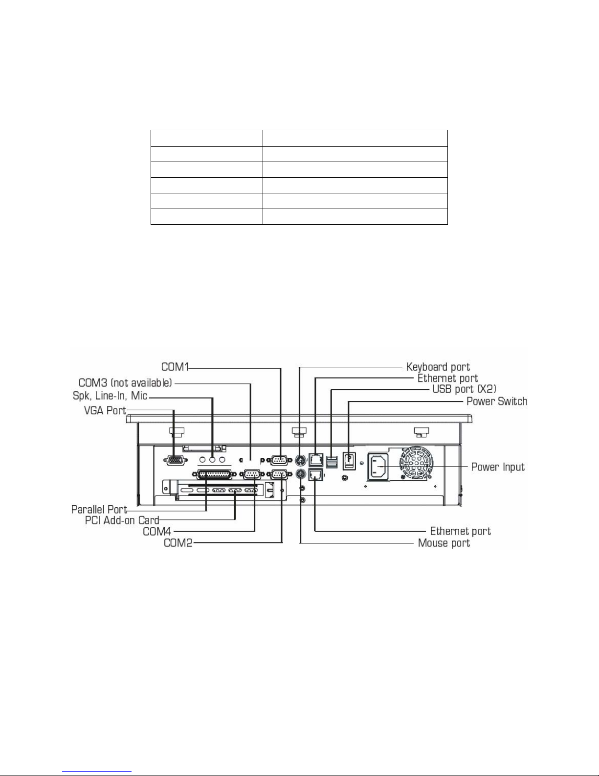
I/O PANEL....................................................................................................................................................................2
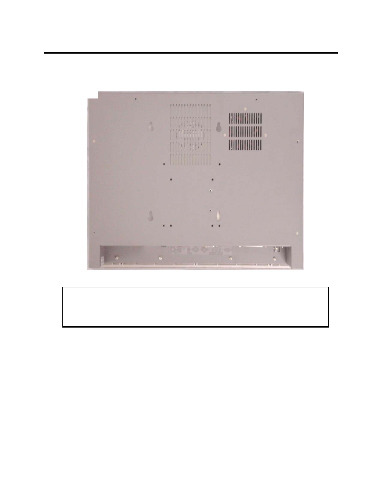
BACK PANEL ................................................................................................................................................................3
FRONT AND SIDE PANELS ..............................................................................................................................................4
UNPACKING THE SYSTEM...............................................................................................................................................5
QUICK STARTUP ...........................................................................................................................................................5
CHAPTER 2 — INSTALLATION...................................................................................................................................6
INSTALLATION OVERVIEW...............................................................................................................................................6
MECHANICAL DIMENSIONS .............................................................................................................................................8
MOUNTING OPTIONS .....................................................................................................................................................9
Panel Mounting......................................................................................................................................................9
Wall Mounting ......................................................................................................................................................11
Arm Mounting.......................................................................................................................................................13
CHAPTER 3 – POS-478 CPU BOARD AND AMI BIOS SETUP.................................................................................14
POS-478E CPU BOARD ............................................................................................................................................14
Product Overview.................................................................................................................................................14
Specifications.......................................................................................................................................................14
POS-478E CPU BOARD LAYOUT................................................................................................................................15
Jumper Settings...................................................................................................................................................16
Connector Pin Outs..............................................................................................................................................21
AMI BIOS SETUP.......................................................................................................................................................31
Starting Setup ......................................................................................................................................................31
Using Setup..........................................................................................................................................................32
Getting Help.........................................................................................................................................................32
Main Menu ...........................................................................................................................................................33
STANDARD CMOS SETUP ...........................................................................................................................................34
Advanced CMOS Setup.......................................................................................................................................36
ADVANCED CHIPSET SETUP.........................................................................................................................................39
POWER MANAGEMENT SETUP......................................................................................................................................41
PCI /PLUG AND PLAY SETUP.......................................................................................................................................42
PERIPHERAL SETUP ....................................................................................................................................................43
Hardware Monitor Setup ......................................................................................................................................44
CHAPTER 4 – MAINTENANCE...................................................................................................................................46
GENERAL PREVENTIVE MAINTENANCE ..........................................................................................................................46
Fuse Replacement...............................................................................................................................................46
RECOMMENDED HARD DRIVE PREVENTIVE MAINTENANCE ..............................................................................................46
PRODUCT REPAIR PROGRAM /RETURNING A UNIT TO XYCOM AUTOMATION .....................................................................47
CHAPTER 5 – TROUBLESHOOTING.........................................................................................................................48
DIAGNOSTIC TESTING..................................................................................................................................................48
RUNNING THE TESTS...................................................................................................................................................50
REINSTALLING OPERATING SYSTEMS............................................................................................................................51
Windows
®
2000 Reinstallation .............................................................................................................................51
Windows XP®Reinstallation.................................................................................................................................51
INSTALLING DRIVERS...................................................................................................................................................52
Video Drivers........................................................................................................................................................52
Touch Screen Drivers ..........................................................................................................................................52
Miscellaneous Drivers..........................................................................................................................................53

4115T Light Duty Industrial PC Table of Contents
ii 143926(A)
APPENDIX A TECHNICAL SPECIFICATIONS...........................................................................................................54
HARDWARE SPECIFICATIONS........................................................................................................................................54
ENVIRONMENTAL SPECIFICATIONS................................................................................................................................55
APPENDIX B – WATCHDOG TIMER..........................................................................................................................56
APPENDIX C – POWER-ON SELF-TEST MESSAGES..............................................................................................58
POST MESSAGES ......................................................................................................................................................58
POST BEEP ..............................................................................................................................................................58
ERROR MESSAGES .....................................................................................................................................................58
APPENDIX D – DMA, IRQ AND 1ST MB MEMORY.....................................................................................................61
DMA CHANNEL ASSIGNMENTS.....................................................................................................................................61
IRQ MAPPING CHART .................................................................................................................................................61
1ST MB MEMORY ADDRESS MAP ..................................................................................................................................62
I/O ADDRESSES..........................................................................................................................................................62
APPENDIX E – HOW TO USE THE WAKE-UP FUNCTION.......................................................................................63
WAKE-UP ON MODEM (RING)......................................................................................................................................63
WAKE-UP ON LAN.....................................................................................................................................................63
APPENDIX F – HOW TO UPGRADE A NEW BIOS....................................................................................................64
BIOS UPDATE PROCEDURE.........................................................................................................................................64
RECOVERING YOUR OLD BIOS....................................................................................................................................65

1 143926(A)
Chapter 1 – Introduction
General Information
The 4115T 15" LCD TFT Panel PC, takes advantage of a modern flat-panel display,
POS-478E CPU board, drive spaces and a power supply for minimum size. It is an
IBM PC/AT® compatible computer specially designed to meet the applications for
industrial environments.
Standard Features
The 4115T comes standard with the following features:
•POS-478E CPU board equipped with a high performance socket Pentium®4
2.0GHz CPU with 533 MHz front system bus and 512 KB cache
•10/100Mbps Ethernet
•LCD/CRT interface
•15” flat panel TFT XGA (1024 x 768) LCD
•100-240 VAC, 50-60 Hz power supply
•Analog resistive touch screen
•Internal 40GB hard disk drive
•1.44 MB floppy disk drive
•Slim line CD-ROM drive
•DDR 266, 256MB SDRAM DIMM
•Windows 2000 Operating System
Optional Features:
•DDR 266 512MB -1G SDRAM DIMM
•CD-R/W
•DVD-ROM
•DVD +/-RW with CD-R/W
•Windows XP
LCD Display
Table 1-1 identifies the features of the 4115T LCD display.
Table 1-1. 4115T LCD Display Specifications
Display Model NEC
Display Type 15” TFT color
Resolution 1024x768
Maximum colors 24 bits
Brightness 250 cd/m2
Backlight MTBF 50,000 hrs

4115T Light Duty Industrial PC Chapter 1 – Introduction
2 143926(A)
Touch Screen
Table 1-2 identifies important specifications of the 4115T touch screen.
Table 1-2. 4115T Touch Screen Specifications
Touch Screen Model Description
Screen Type Eight wire analog resistive touch screen
Resolution Continuous
Light Transmission Typical value 75%
Surface Hardness 4H (Test condition: ASTM D3363-92A)
Support Driver Supports Windows 2000/XP
The figures on the next several pages show the internal and external components on
the front and back panels of the unit to help you locate features relevant to
installation.
I/O Panel
The figure below shows the I/O panel of the 4115T.
Figure 1-1. I/O Panel
Note: There is only one Ethernet port available

4115T Light Duty Industrial PC Chapter 1 – Introduction
3 143926(A)
Back Panel
The diagram below shows the back panel of the 4115T. For maintenance, installation
or upgrade, first remove the back cover by unfastening seven screws as shown in the
diagram below.
Figure 1-2. System Back Panel
Caution
Before any installation or un-installation, please take precautions to prevent damage
to the components due to static electricity.

4115T Light Duty Industrial PC Chapter 1 – Introduction
4 143926(A)
Front and Side Panels
One Floppy Disk Drive and CD-ROM are accessible from the side of the chassis.
Figure 1-3. Front and Side Panel Views
Floppy Disk
Drive
CD-ROM
Drive
Logo

4115T Light Duty Industrial PC Chapter 1 – Introduction
5 143926(A)
Unpacking the System
When you remove the system from its shipping container, verify that you have the
parts listed below. Save the box and inner wrapping in the event you need to reship
the unit.
•4115T Unit
•Documentation kit, which includes:
Power cable
Twelve 10-32 hex nuts
Documentation and Support Library CD-ROM
Operating System Recovery Media or retail operating system (CD-ROM)
Quick Startup
This section gives you the steps to get the system up and running without explaining
the capabilities and options.
Warning
Remove power from the unit and disconnect the power cord before making any
adjustments to the inside or outside of the computer.
To prepare the system for use, perform the following steps.
1. Attach optional keyboard to the keyboard port, and optional mouse to the mouse
port.
2. Confirm that the 100-240 VAC selector switch on the power supply is set
appropriately.
3. Attach the power cord from the power receptacle to a properly grounded 100-240
VAC, 50-60 Hz outlet.
4. Turn on power to the unit (via an outlet power switch if applicable). The system
will boot up into the operating system.
5. Install application software via the floppy, the CD-ROM, or the network.

6 143926(A)
Chapter 2 — Installation
Installation Overview
The rugged design of the 4115T unit allows it to be installed in most industrial
environments. The system is generally placed in a NEMA 4/4X/12 enclosure to
protect against contaminants such as dust, and moisture. Metal enclosures also help
minimize the effects of electromagnetic radiation that nearby equipment can generate.
Read the following sections carefully to be sure that you are complying with all the
safety requirements.
1. Select a NEMA rated enclosure and place the unit to allow easy access to the
system ports (see other sections in this chapter and Appendix A).
To assure a NEMA 4 seal choose an approved enclosure that has a 14-
gauge (0.075 in/1.9 mm thick steel or 0.125 in/3.2 mm thick aluminum)
front face.
Be sure to account for the unit’s depth when choosing the depth of the
enclosure.
2. Create a cutout in the enclosure (see Figure 2-2).
Be sure to place the unit at a comfortable working level
Make sure the area around the cutout is clean and free from metal burrs
3. Mount the unit in an upright position and properly secure the unit into the panel.
Tighten the ten #10 nuts to 25 inch-pounds (2.8 Newton-meters / 28Kgf
cm).
4. Attach one end of the power cord to the power receptacle on the unit and the
other end to a properly grounded 100-240 VAC, 50-60 Hz outlet.
5. Turn on power to the system. The system will boot up the installed operating
system.
6. Install the application software via a floppy drive, CD-ROM, or the network.
Additional aspects to take into account when mounting your 4115T unit:
•Consider locations of accessories such as AC power outlets and lighting (interior
lighting and windows) for installation and maintenance convenience
•Prevent condensation by installing a thermostat-controlled heater or air
conditioner
•To allow for maximum cooling, avoid obstructing the airflow

4115T Light Duty Industrial PC Chapter 2 – Installation
7 143926(A)
•Place any fans or blowers close to the heat generating devices. If using a fan,
make sure that outside air is not brought into the enclosure unless a fabric or
other reliable filter is used. This filtration prevents conductive particles and other
harmful contaminants from entering the enclosure.
•Do not select a location near equipment that generates excessive electromagnetic
interference (EMI) or radio frequency interface (RFI). Examples of these types of
equipment are: high power welding machines; induction heating equipment; and
large motor starters.
•Place incoming power line devices (such as isolation or constant voltage
transformers, local power disconnects, and surge suppressers) away from the
system. The proper location of incoming line devices keeps power wire runs as
short as possible and minimizes electrical noise transmitted to the unit.
•Make sure the location does not exceed the unit’s shock, vibration, and
temperature specifications
•Install the unit in the rack or panel in such a way as to ensure that it does not
cause a hazard from uneven mechanical loading
•Incorporate a readily-accessible disconnect device in the fixed wiring on
permanently connected equipment
•Avoid circuit overloading of the supply circuit

4115T Light Duty Industrial PC Chapter 2 – Installation
8 143926(A)
Mechanical Dimensions
Front Panel: 16.14” (410 mm) x 12.16” (309 mm) x 0.315” (8 mm) (WxHxD)
Cabinet: 15.1” (383.6 mm) x 11.13” (282.6 mm) x 3.93” (99.9 mm) (WxHxD)
Note: All dimensions in inches (mm)
Figure 2-1. Unit Dimensions

4115T Thin Line Industrial Flat Panel PC Chapter 2 –
Installation
9 143926(A)
Mounting Options
The 4115T can be mounted to a panel, to the wall, or to an arm. The following
sections describe each mounting option for the 4115T.
Panel Mounting
The 4115T is designed for panel mounting. Before mounting the 4115T to the panel,
check the cut out dimensions as shown in Figure 2-2. Then, mount it to the panel
using ten supporters, as shown in the Figure 2-3 (see next page).
Figure 2-2. Panel Cutout Dimensions

4115T Thin Line Industrial Flat Panel PC Chapter 2 –
Installation
10 143926(A)
Figure 2-3. Panel Mounting Diagram

4115T Thin Line Industrial Flat Panel PC Chapter 2 –
Installation
11 143926(A)
Wall Mounting
The 4115T is suitable for wall mount using the included brackets and hardware. See
Figure 2-4 for wall mounting dimensions. See Figure 2-5 for a wall-mounting
diagram.
All dimensions in inches (mm)
Figure 2-4. Wall Mounting Dimensions

4115T Thin Line Industrial Flat Panel PC Chapter 2 –
Installation
12 143926(A)
Figure 2-5. Wall Mounting Diagram

4115T Thin Line Industrial Flat Panel PC Chapter 2 –
Installation
13 143926(A)
Arm Mounting
The 4115T also accommodates 75/100 mm interface pads for arm mounting. Figure
2–6 gives the dimensions for arm mounting.
All dimensions in inches (mm)
Figure 2-6. Arm Mounting Dimensions

14 143926(A)
Chapter 3 – POS-478 CPU Board and AMI BIOS
Setup
POS-478E CPU Board
Product Overview
The 4115T is equipped with a POS-478E Socket 478 Pentium 4 with CPU control
board. It is equipped with a high-performance processor and advanced high
performance multi-mode I/O.
This board has a built-in AGP4X VGA (Intel 845GV) VGA controller, which shares
8MB or more of system DDR-SDRAM. The on-chip UARTs are compatible with the
NS16C550. The parallel port and IDE interface are compatible with IBM PC/AT
architecture. The POS-478E also has one 10/100 Fast Ethernet LAN built-in (ICH4).
Specifications
•CPU: Supports Intel Pentium 4 processor, and 400/533MHz FSB.
•Expansion Bus: PCI bus, expansion to support PCI bus signal
•DMA channels: 7
•Interrupt levels: 15
•Chipset: Intel 845GV (GMCH); Intel 82801DB (ICH4) real-time clock
•RAM: Two 184-pin DIMM sockets support DDR 200/266 SDRAM, up to 2GB.
•Built-in AGP2.0 4X 3D graphics engine, which shares system DDR SDRAM 8M or
more as needed.
•Up to four PCI enhanced ATA/100 IDE hard drives, which can handle data transfers
of up to 100MB/s and are compatible with existing ATA-2 IDE specifications
•Supports up to two floppy disk drives, 5.25” (360KB and 1.2MB) and/or 3.5”
(720KB, 1.44MB, and 2.88MB)
•Four serial ports: 16C550 UART (or compatible) with 16-byte FIFO buffer, support
up to 115.2Kbps (three ports total external to the 4115T, as one is used for the touch
screen)
•Bi-directional parallel port
•Two USB 2.0 ports
•Watchdog timer: Can be set to 1 minute (minimal) or above period.

4115T Light Duty Industrial PC Chapter 3 – POS-478 CPU Control Board and BIOS Setup
15 143926(A)
•AC’97 Audio CODEC
•Compact Flash operates with a passive adapter (True IDE Mode) in a Type I/II
Socket
•Wake-Up Function: Supports Wake-On-Lan and Wake-On-Ring.
•Mouse & Keyboard PS/2 Connectors
POS-478E CPU Board Layout
Figure 3-1. POS-478E Board Layout
Note: JP17 is not populated on the POS-478 motherboard.

4115T Light Duty Industrial PC Chapter 3 – POS-478 CPU Control Board and BIOS Setup
16 143926(A)
Caution
Some components on POS-478E are very sensitive to static discharges. To protect
it from unintended damage, be sure to follow these precautions:
1. Ground yourself to remove any static charge before touching your POS-478E.
You can do it by using a grounded wrist strap at all times or by frequently touching
any conducting materials that is connected to the ground.
2. Handle your POS-478E by its edges. Don’t touch IC chips, leads or circuitry if not
necessary.
3. Do not plug any connector or jumper while the power is on.
4. Do not put your POS-478E unprotected on a flat surface, as the board has
components on both sides.
Jumper Settings
The following table lists the functions of all the jumpers on the 4115T. The following
sections describe how to set jumpers on the POS-478 board.
Table 3-1. Jumper Functions
Label Function
JP1 CMOS State Setting
JP2 LCD Voltage Setting
JP3 LCD 24 bit or 18 bit LCD Setting
JP4 LCD CLK Signal Setting
JP5 LCD Single Pixel or Dual Pixel Setting
JP6 Set pin 9 of COM2 Voltage Setting
JP7 Set pin 9 of COM1 Voltage Setting
JP8 Set pin 9 of COM2 as Signal RI or Voltage Setting
JP9 Set pin 9 of COM1 as Signal RI or Voltage Setting
JP10 COM2 Mode Setting
JP11 COM2 Mode RS-232 or RS-422/RS-485 Setting
JP12 Compact Flash Master/Slave Setting
JP13 Set pin 9 of COM3 Voltage Setting
JP14 Set pin 9 of COM4 Voltage Setting
JP15 Set pin 9 of COM3 as Signal RI or Voltage Setting
JP16 Set pin 9 of COM4 as Signal RI or Voltage Setting
JP18 Keyboard & Mouse Power Source Setting
JP19 Enable or Disable Serial ATA (only for POS-478S)
Table of contents
Other Xycom Industrial PC manuals

Xycom
Xycom 9450 User manual

Xycom
Xycom 1510 User manual

Xycom
Xycom 3700 Series User manual

Xycom
Xycom 9462 User guide

Xycom
Xycom 4117T User manual

Xycom
Xycom 3500 Series User manual

Xycom
Xycom 4600 Series User manual

Xycom
Xycom 3510T User guide

Xycom
Xycom 3400 Series Application guide

Xycom
Xycom 3600 Series 3612T User manual