manuals.online logo
Brands
  1. Home
  2. •
  3. Brands
  4. •
  5. Xylem
  6. •
  7. Water Pump
  8. •
  9. Xylem Jabsco 18620-0003 User manual

Xylem Jabsco 18620-0003 User manual

Other Xylem Water Pump manuals

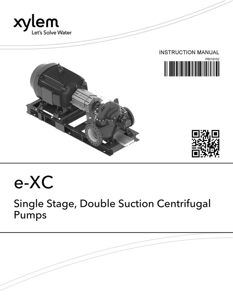
Xylem Bell & Gossett VSX Series User manual

Xylem

Xylem Bell & Gossett VSX Series User manual

Xylem rule DB412 User manual

Xylem

Xylem rule DB412 User manual

Xylem Flojet CW474 Series User manual

Xylem

Xylem Flojet CW474 Series User manual

Xylem LOWARA Manual

Xylem

Xylem LOWARA Manual

Xylem FLOJET Triplex Series User manual

Xylem

Xylem FLOJET Triplex Series User manual

Xylem Flygt 2075 User manual

Xylem

Xylem Flygt 2075 User manual

Xylem e-IXP Manual

Xylem

Xylem e-IXP Manual

Xylem NPE User manual

Xylem

Xylem NPE User manual

Xylem GOULDS LB User manual

Xylem

Xylem GOULDS LB User manual

Xylem Bell & Gossett Domestic CU Series User manual

Xylem

Xylem Bell & Gossett Domestic CU Series User manual

Xylem FLOJET VFLO 5.0 User manual

Xylem

Xylem FLOJET VFLO 5.0 User manual

Xylem LOWARA ESHS ATEX User manual

Xylem

Xylem LOWARA ESHS ATEX User manual

Xylem FLOJET R3521/03521 Series Operating and installation instructions

Xylem

Xylem FLOJET R3521/03521 Series Operating and installation instructions

Xylem Goulds CentriPro Series User manual

Xylem

Xylem Goulds CentriPro Series User manual

Xylem FLOJET 2840 Series Operating and installation instructions

Xylem

Xylem FLOJET 2840 Series Operating and installation instructions

Xylem McDonnell & Miller MM-706B User manual

Xylem

Xylem McDonnell & Miller MM-706B User manual

Xylem Lowara e-IXP Manual

Xylem

Xylem Lowara e-IXP Manual

Xylem Flygt Concertor 6020 User manual

Xylem

Xylem Flygt Concertor 6020 User manual

Xylem Goulds GB Series Manual

Xylem

Xylem Goulds GB Series Manual

Xylem LOWARA SEKAMATIK 50E Series Service manual

Xylem

Xylem LOWARA SEKAMATIK 50E Series Service manual

Xylem Bell & Gossett ecocirc XL Troubleshooting guide

Xylem

Xylem Bell & Gossett ecocirc XL Troubleshooting guide

Xylem Bell & Gossett 1522 Series User manual

Xylem

Xylem Bell & Gossett 1522 Series User manual

Xylem Laing Thermotech ecocirc E Series User manual

Xylem

Xylem Laing Thermotech ecocirc E Series User manual

Xylem GOULDS e-SVI Series User manual

Xylem

Xylem GOULDS e-SVI Series User manual

Popular Water Pump manuals by other brands

Watershed Innovations HYDRAPUMP SMART FLEX Instructional manual

Watershed Innovations

Watershed Innovations HYDRAPUMP SMART FLEX Instructional manual

Graco Modu-Flo AL-5M instructions

Graco

Graco Modu-Flo AL-5M instructions

Messner MultiSystem MPF 3000 operating instructions

Messner

Messner MultiSystem MPF 3000 operating instructions

WilTec 50739 Operation manual

WilTec

WilTec 50739 Operation manual

Franklin Electric Little Giant 555702 HRK-360S instruction sheet

Franklin Electric

Franklin Electric Little Giant 555702 HRK-360S instruction sheet

Ingersoll-Rand PD02P Series Operator's manual

Ingersoll-Rand

Ingersoll-Rand PD02P Series Operator's manual

VS ZJ Series Operating	 instruction

VS

VS ZJ Series Operating instruction

Flotec FPZS50RP owner's manual

Flotec

Flotec FPZS50RP owner's manual

SKF Lincoln FlowMaster II User and maintenance instructions

SKF

SKF Lincoln FlowMaster II User and maintenance instructions

Water Duro Pumps DCJ500 Operating & installation instructions

Water

Water Duro Pumps DCJ500 Operating & installation instructions

Action P490 Operating instructions & parts manual

Action

Action P490 Operating instructions & parts manual

Flo King Permacore Reusable Carbon Bag Disassembly. & Cleaning Instructions

Flo King

Flo King Permacore Reusable Carbon Bag Disassembly. & Cleaning Instructions

ARO ARO PD15P-X Operator's manual

ARO

ARO ARO PD15P-X Operator's manual

Pumptec 112V Series Operating instructions and parts manual

Pumptec

Pumptec 112V Series Operating instructions and parts manual

Virax 262070 user manual

Virax

Virax 262070 user manual

Neptun NPHW 5500 operating instructions

Neptun

Neptun NPHW 5500 operating instructions

Sensidyne Gilian BDX-II Operation & service manual

Sensidyne

Sensidyne Gilian BDX-II Operation & service manual

Wilo Yonos PICO1.0 Installation and operating instructions

Wilo

Wilo Yonos PICO1.0 Installation and operating instructions

manuals.online logo
manuals.online logoBrands
  • About & Mission
  • Contact us
  • Privacy Policy
  • Terms and Conditions

Copyright 2025 Manuals.Online. All Rights Reserved.

Model 18620-0003
RE ERSIBLE PUMP
FEATURES
Body: Bronze
Impeller: Nitrile
Seal: Lip Type
Motor: Reversible Permanent Magnet Type with
Integral Reversing Switch and Fuse
Ports: 3/4" Garden Hose External
Height: 3-3/8" (85mm)
Length: 8-5/8" (172mm)
Width: 4" (95mm)
Weight: 5-1/2 lb (2.5 kg) Approx.
APPLICATION
Use for circulating and draining bait tank, engine oil
changing or general pumping requirements. With a wet
impeller, pump will produce a suction lift of about 3 to 4
feet (0.9 to 1.2m) and a lift of about 10 feet (3m) when
primed. BE SURE SUCTION LINES ARE AIRTIGHT.
INSTALLATION
The pump must be mounted in a dry location - the
motor is not waterproof and must not be submerged.
SELECTION OF A COOL, VENTILATED location will
generally extend pump motor life. The unit can be
mounted in any desired position. It is best to mount so
that water dripping from loose port connection will not
wet the motor. The pump head may be mounted at
90 degree increments on the motor to accommodate
plumbing connections as needed.
PLUMBING CONNECTIONS
Pumps have external hose threads and internal 3/8" pipe
threads. Use hose that does not kink when bent or
collapse due to the suction of the pump. Arrange hoses
to trap liquid in pump body to wet the impeller. Wetting
the impeller aids in priming and extends impeller life. All
hoses must have airtight connections.
HEAD S. FLOW TABLE
Total Head Capacity
PSI Feet Metres GPM LPM
2.1 5 1.5 1.8 6.8
4.3 10 3.0 1.7 6.4
8.7 20 6.1 1.6 6.1
17.4 40 12.2 1.2 4.5
Table shows approximate Head-Flow for new pump.
WARNING
!
Explosion hazard. Do not pump gasoline, solvents,
thinners or other flammable liquids. To do so can
cause an explosion resulting in injury or death.
Explosion hazard. Do not operate with rivets
removed from motor case. Explosion resulting in
personal injury, death or property damage can
occur. Case openings must be sealed to avoid
explosion and maintain ignition protected rating.
WARNING
!
MODEL 18620-0003
ELECTRICAL CONNECTIONS
Connect black wire to negative (–) terminal of battery. The
orange wire should run to a properly sized (see electrical
specification) overload protected switch or circuit breaker,
with a wire from switch or breaker to positive (+) terminal
of battery. Electrical circuit must be independent of all
other accessories. Use proper wire size as determined by
wire table elsewhere on this sheet.
Overload
Protected
Distribution
Panel
Orange +
Black –
Battery
–
+Discharge
clockwise
rotation*
Discharge 
counter
clockwise
rotation*
Explosion hazard. If pump is operated in an area
containing flammable vapors, wire leads must be
joined by insulated mechanical locking connectors.
Loose or inadequate wire connections can spark
resulting in an explosion. Property damage, injury
or death can occur.
WARNING
!
WIRING DIAGRAM
*Motor rotation viewed from pump end cover
NOTICE: Failure to use proper size fuse may damage
motor and void warranty.
ELECTRICAL SPECIFICATIONS
Model No. Volta e Amp Draw Fuse Size
18620-0003 12V DC 7 10 Amp
MINIMUM WIRE SIZES
Wire Len th
Between Battery
and Motor Wire Gau e
1-10 ft. (3m) #14
11-20 ft. (6m) #10
21-30 ft. (9m) #10
NOTICE: To prevent motor damage, use only multi-
strand copper wire in size recommended. DO NOT use
ordinary lamp cord or other substitutes.
OPERATION
Flexible impeller pumps must NOT be run dry, as the
pumped liquid is the lubricant for the impeller. Observe the
outlet and shut off pump as soon as liquid stops flowing.
The pump cannot run against a closed outlet such as
encountered when using a garden hose type shut-off
nozzle.
Temperature of pumped liquid may be in the range of
45° - 160°F (10° - 70°C).
Pressure for normal operation should not exceed 40 feet
of head (17.4 psi).
MAINTENANCE
Check wires and connections to be sure corrosion is not
adding additional resistance to the motor circuit and
causing a low voltage condition at the motor. Low voltage
can inhibit starting and cause fuse to blow. Full voltage
should be available to prevent motor damage.
NOTICE: If pump is idle for extended periods, the
impeller may stick to the pump body, preventing motor
rotation and causing blown fuses. To correct, remove
end cover and impeller. Clean body and impeller, then
lubricate with water or small amounts of grease before
assembly.
If pump is to be in freezing temperatures, drain by
loosening end cover.
A service kit, or at least a spare impeller, should be
carried aboard to be assured of pumping capability.
PARTS LIST
Key Description Number
A Screw Kit (includes 3 screws) 18647-1000
End Cover
H *O-Ring 18753-8660
B Impeller 14750-0003
Seal
D Screw Kit (includes 3 screws) 18153-4384
Slinger
E Body (use pump head assembly) 9040-1001
Motor: 12 volt, EMC
F Toggle Switch Boot 18753-6067
Switch Polarity Reversing
*O-ring gasket contained in Kits A, B, D.
EXPLODED IEW
DIMENSIONAL DRAWING
Inches (Millimetres)
SER ICE INSTRUCTIONS
DISASSEMBLY
1. Remove end cover screws, end cover and o-ring.
2. Withdraw impeller.
3. Loosen and remove two slotted hex screws, which
attach body to motor.
4. Tap body lightly between ports and remove body
from motor.
5. With a 1/2” diameter dowel, push agains the shaft
seal from back (motor) side of the body to dislodge
it from the seal bore.
NOTE: Do not tamper with or disassemble motor.
ASSEMBLY
1. Lubricate seal with water and position it in seal bore
with lip, or hollowed-out side of seal, pointing
towards the impeller bore. With a 1/2” diameter
dowel, push against the shaft seal into its bore until
it contacts the bottom.
2. Lubricate motor shaft and install body on motor.
3. Lubricate impeller bore and, aligning flat in impeller
with flat on motor shaft, install impeller with closk-
wise rotary motion.
4. Install O-ring, end cover and screws.
REPLACEMENT PART KITS
ABSCO RECOMMENDS THAT ALL COMPONENTS IN
EACH INDIVIDUAL KIT BE REPLACED AS A MATTER OF
GENERAL MAINTENANCE.
A- Plate Kit
H- O-Ring
B- Impeller Kit
D- Seal Kit
E- Body Kit
F- Motor Kit
A. LIMITED WARRANTY:
absco warrants that at the time of shipment, the
products manufactured by absco and sold hereunder
shall be in conformity with applicable written
specifications and descriptions referred to or set
forth herein, free from defects in material and,
merchantable, and suitable for a particular purpose,
provided such is implied by State law under the
circumstances of this sale.
B. WARRANTY ADJUSTMENT:
1. absco agrees to repair or furnish a replacement for,
but not to remove or install, any product or
component thereof which, within one (1) year from
date of purchase, shall upon test and examination
by absco prove defective within the above
warranty. Receipt verifying purchase date is required
to obtain adjustment.
2. Buyer shall notify absco of any defect within this
warranty no later than ninety (90) days after the
defect is discovered.
C. EXCLUSIONS FROM WARRANTY AND
LIMITATION OF LIABILITY:
1. The foregoing warranty is limited solely as set
forth herein and applies only for the period
designated above.
2. ABSCO SHALL NOT BE LIABLE FOR ANY LOSS,
DAMAGE, SPECIAL OR CONSEQUENTIAL
DAMAGE OF ANY KIND, WHETHER BASED
UPON WARRANTY, CONTRACT, NEGLIGENCE,
OR STRICT LIABILITY ARISING IN CONNECTION
WITH THE SALE, USE, OR REPAIR OF THE
PRODUCT.
3. THE MAXIMUM LIABILITY OF ABSCO IN
CONNECTION WITH THIS WARRANTY SHALL
NOT IN ANY CASE EXCEED THE CONTRACT
PRICE FOR THE PRODUCT CLAIMED TO BE
DEFECTIVE OR UNSUITABLE.
4. This warranty does not extend to any product
manufactured by absco which has been subjected
to misuse, neglect, accident, improper installation, or
use in violation of instructions furnished by absco.
5. This warranty does not extend to or apply to any unit
which has been repaired or altered at any place
other than absco’s factory, or by persons not
expressly approved by absco, nor to any unit the
serial number, model number, or identification of
which has been removed, defaced or changed.
6. Components manufactured by any supplier other
than absco shall bear only that warranty made by
the manufacturer of that product.
7. This warranty applies to products defined as
“consumer products” by the Consumer Product
Warranties Act as from time to time amended.
D. CONSUMER RIGHTS:
This warranty gives you specific legal rights, and you
may have other rights which vary from state to state.
Some states do not allow exclusion or limitation
of damages.
STANDARD WARRANTY: If the products manufactured
and sold hereunder are not Consumer Products, the
warranty extended to Buyer shall be as set forth in
subparagraphs (A), (B), and (C), EXCEPT THAT ALL
EXPRESS OR IMPLIED WARRANTIES OR
MERCHANTABILITY OR SUITABILITY FOR ANY
PARTICULAR PURPOSE ARE EXCLUDED.
ONE YEAR LIMITED WARRANTY
THE PRODUCTS DESCRIBED HEREIN ARE
SUB ECT TO THE ABSCO ONE YEAR LIMITED
WARRANTY, WHICH IS AVAILABLE FOR YOUR
INSPECTION UPON REQUEST.
Jabsco is a trademark of Xylem Inc. or one of its subsidiaries.
© 2012 Xylem, Inc. 43000-0462 Re B 10/2012
www.xylemflowcontrol.com
Jabsco, 100 Cummings Center, Ste. 535-N, Beverly, MA 01915
Tel: +1 978 281 0440 Fax: +1 978 283 2619
Jabsco, Bingley Road, Hoddesdon, Hertfordshire, EN11 0BU
Tel: +44 (0) 1992 450 145 Fax: +44 (0) 1992 467 132
NHK Jabsco Co Ltd, 3-21-10, Shin - Yokohama Kohoku-ku, Yokohama 222
Tel: +81 (0) 45 475 8906 Fax: +81 (0) 45 475 8908
Jabsco GmbH, Oststraße 28, 22844 Norderstedt
Tel: +49 (0) 40 53 53 73 0 Fax: +49 (0) 49 53 53 73 11
Jabsco Italia, s.r.l., Via Tommaseo, 6, 20059 Vimercate, Milano
Tel: +39 039 685 2323 Fax: +39 039 666 307
USA
UK
JAPAN
GERMANY
ITALY