5
Slow fill mode
All Hydrovar sets are fitted with slow fill controls to help prevent excessive pressures being excreted on system
pipe work when the set comes back on line after a power outage or low water condition.
Slow fill operation
When the set powers up or comes back on line after a low water condition it will automatically inhibit all pumps
except pump 1 which will ramp up slowly and maintain a set point approximately equal to the height of the build-
ing (system pressure – 2 bar) it will remain at this set point until the delay timer normally set for two minutes (ad-
justable) times out and resets the Hydrovars to set point one allowing pump one to speed up to the normal
system set point and release all other pumps to cascade in as required.
Commissioning
With the main power isolated check:
1.The break tank feeding the set is filled with water.
2.The set/system vessels have been charged with Nitrogen to the correct pressure (set point -0.2 bar).
3.Open suction line isolation valve where fitted.
4.Open suction and discharge pump isolation valves.
5.Close main discharge isolation valve.
6.Open the pump vents at the top of each pump.
7.Allow all air to escape until water flows freely.
8.Close pump vent valves.
9.Open discharge valve.
10.Ensure all vessel valves are open.
11.Switch the main power supply on.
12.Check the set point is as required.
13.Switch the inverters to the on position by pressing the up button Note: only 1 pump will be allowed to run in
the first two minutes of power up after which all other pumps will be released to run.
Once the system pressure has been satisfied the last pump should ramp down and after a short while
stop completely until a demand is placed on the system again.
Operation
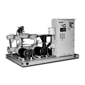
The booster set is designed to maintain a constant system pressure with varying flows.
Each Hydrovar head has its own 4-20ma transducer which monitors the system pressure at all times.
If one Hydrovar or transducer fails the next Hydrovar will take on the master function. All Hydrovars talk to
each other through a RS485 serial coms link. Each Hydrovar head is fitted with four function keys: Up/Down
Left/Right these are used to navigate through the parameters and change as appropriate. Three LEDs are
provided to indicate: Power-Run-Error.
When a demand is placed on the system, water will be supplied from any vessels that are fitted to the system,
once this supply is depleted the system pressure will start to fall, when the pressure falls 0. 15 bar (par 0510)
below the system set point the first Hydrovar will start to ramp up to maintain the set point, if demand in-
creases and the first Hydrovar reaches maximum speed and again the system pressure falls 0.15 bar blow
set point the next Hydrovar will be called in to ramp up and assist the first pump, the set point will have been
raised by 0.35 bar (par 0505) to give a differential between pumps. All the time demand increases, further
Hydrovars will be called in to assist until all Hydrovars are running. When demand reduces the last Hydrovar
to be called in will start to ramp down and eventually stop, if demand continues to decrease the next Hydrovar
will start to ramp down and stop, this will continue until all Hydrovars have stopped. The next time the
pressure falls the same sequence as above will operate except the first Hydrovar to operate will have been
rotated so all Hydrovars have even usage. See Fig1 below
On sets where a Jockey pump is fitted the sequence will be for the jockey pump to be the first to operate on
all occasions and it will not be connected to the main Hydrovars with a coms link.
If a low level in the break tank occurs all pumps will be stopped until the water supply has been reinstated,
the pumps will then be automatically released to resume normal operation.
The booster set has a remote inhibit facility allowing the set to be stopped/started from a remote source (open
contact to inhibit) See electrical drawing for connection details.
