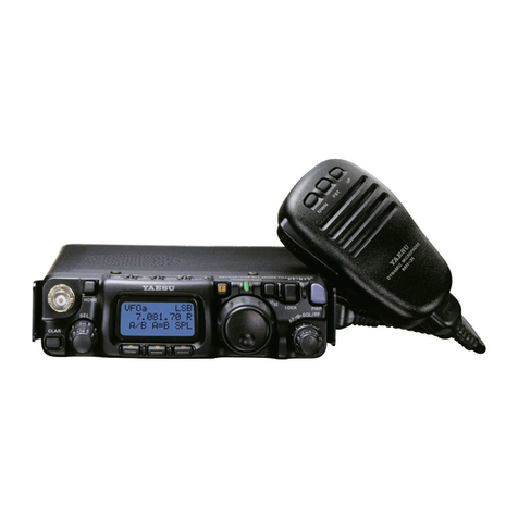
Yaesu FTM-500DR User manual

C4FM/FM 144/430MHz
DUAL BAND DIGITAL TRANSCEIVER
FTM-500DR
Operating Manual

Contents.......................................................... 2
Quick Guide .................................................... 3
Safety Precautions (make sure to read
these)............................................................... 4
Controls & Connections ................................ 7
Supplied Accessories .................................... 9
Connecting the Power Supply....................... 9
Connecting the car Battery .............................................9
Connecting the external power supply equipment........9
Using a microSD Memory Card................... 10
Usable microSD Memory Cards ..................................10
Installing the micro-SD card .........................................10
Removing the micro-SD card .......................................10
Formatting a microSD Memory Card...........................10
Basic Operations.......................................... 11
Turning the Transceiver ON ..........................................11
Adjusting the Volume Level...........................................11
Adjusting the squelch setting ........................................11
Toggling the Operating Band ........................................12
Selecting a Frequency Band.........................................12
Tuning to a Frequency...................................................12
Changing the Frequency Step .................................12
Selecting the Communication Mode............................12
Fixing the Communication Mode.............................14
Transmission..................................................................14
Changing the Transmission Power Level ....................14
Locking Keys and DIAL knob........................................14
Repeater Operation ...................................... 15
Communicating Via the Repeater ................................15
Using the Memory ........................................ 16
Registering to Memory Channels.................................16
Recalling a Memory Channel .......................................16
Clearing Memories ........................................................16
Recalling the Home Channels......................................16
Changing the Home Channel Frequency ....................17
Split Memory ..................................................................17
Using Memory Tag ........................................................17
Scanning Function ....................................... 18
VFO Scan.......................................................................18
Memory Channel Scanning ..........................................18
Programmable Memory scan (PMS) ...........................18
Convenient Functions.................................. 19
Bluetooth®Operation.....................................................19
When connecting to a Bluetooth Headset for the first
time -Pairing-..................................................................19
Hands-free operation with a Bluetooth headset (VOX
function) ..........................................................................19
Send by pressing the button on the Bluetooth®
headset (when the VOX function is off) .......................19
VOX Operation...............................................................20
Setting VOX function.................................................20
Set the VOX (automatic voice transmission) delay
time .................................................................................20
Band Scope....................................................................21
GPS Function.................................................................21
Tone squelch feature.....................................................21
Digital Code squelch (DCS) feature.............................21
Digital Personal ID (DP-ID) feature ..............................21
Using Set Mode............................................. 22
Set Mode Operation ......................................................22
Tables of Set Mode Operations ................... 22
Restoring to Defaults (Reset)...................... 29
All Reset .........................................................................29
Specifications ............................................... 30
Contents

3
ÀTurning the Power ON
Press and hold the [POWER] switch.
ÁInputting the Call sign
When turning the power ON for the first
time after purchasing, input the call sign of
your own station.
1. When turning the power ON for the first
time after purchasing, the call sign input
screen will be displayed.
2. Input the call sign.
Rotate the FUNC knob to select each
character, then press the FUNC knob to
move the cursor to the right.
3. Repeat step 2 to input the remaining
call sign characters.
Rotate the FUNC knob to select ,
then press the FUNC knob to move the
cursor to the left.
5. Press and hold the FUNC knob to con-
clude inputting.
Normal operation (VFO Mode) screen
will be displayed.
ÂSelecting the Operating Band
Press the [BAND] key.
ÃTuning the frequency
Rotate the DIAL knob.
ÄAdjusting the volume
Rotate the VOL/SQL knob to adjust the
volume to a comfortable level.
ÅAdjusting the squelch setting
The squelch level may be adjusted to mute
the background noise when no signal is
received.
1. Press the VOL/SQL knob.
2. Rotate the FUNC knob to adjust the
squelch to a level at which the back-
ground noise is muted.
* When the squelch level is increased,
the noise is more likely to be silenced,
but it may become more difficult to
receive weak signals.
3. Press the VOL/SQL knob to save the
setting.
ÆSelecting the
Communication Mode
The communication mode is automatically
selected to correspond to the signal being
received.
Press the [D X] to manually select the
communication mode.
Ç
Transmitting/Receiving Signals
Transmitting
While pressing and holding the PTT
speak into the microphone.
Receiving
Release the PTT to return to receive
mode.
Quick Guide

4
Safety Precautions (make sure to read these)
Make sure to read this manual in order to use this radio safely and correctly.
Note beforehand that the company shall not be liable for any damages suffered by the
customer or third parties in using this product, or for any failures and faults that occur
during the use or misuse of this product, unless otherwise provided for under the law.
Type and meaning of the marks
DANGER
This symbol indicates the possibility of death or serious in-
jury being inflicted on the user and the surrounding people
when these instructions are ignored and the product is han-
dled wrongly.
WARNING
This symbol indicates the possibility of death or serious in-
jury being inflicted on the user and the surrounding people
when these instructions are ignored and the product is han-
dled wrongly.
CAUTION
This symbol indicates the possibility of physical impedi-
ments occurring or impediments being inflicted on the user
and the surrounding people when these instructions are
ignored and the product is handled wrongly.
Type and meaning of symbols
Prohibited actions that must not be carried out in order to use this radio safely.
For example, signifies that disassembly is prohibited.
Precautions that must be adhered to in order to use this radio safely. For ex-
ample, signifies that the power supply is to be disconnected.
DANGER
Do not use the device in “regions or
aircrafts and vehicles where its use
is prohibited” such as in hospitals
and aeroplanes.
This may exert an impact on electronic
and medical devices.
Do not use this product while driving
or riding a motorbike. This may re-
sult in accidents.
Make sure to stop the car in a safe
location first before use if the device is
going to be used by the driver.
Do not operate the device when flam-
mable gas is generated.
Doing so may result in fire and explo-
sion.
Do not transmit in crowded places
in consideration of people who are
fitted with medical devices such as
heart pacemakers.
Electromagnetic waves from the device
may affect the medical device, resulting
in accidents caused by malfunctions.
Never touch the antenna during
transmission.
This may result in injury, electric shock
and equipment failure.
When an alarm goes off with the
external antenna connected, cut off
the power supply to this radio imme-
diately and disconnect the external
antenna from this radio.
If not, this may result in fire, electric
shock and equipment failure.
Do not touch any liquid leaking from
the liquid display with your bare
hands.
There is a risk of chemical burns occur-
ring when the liquid comes into contact
with the skin or gets into the eyes. In this
case, seek medical treatment immediate-
ly.

5
WARNING
Do not use voltages other than the
specified power supply voltage.
Doing so may result in fire and electric
shock.
Do not transmit continuously for
long periods of time.
This may cause the temperature of the
main body to rise and result in burns
and failures due to overheating.
Do not dismantle or modify the de-
vice.
This may result in injury, electric shock
and equipment failure.
Do not handle the power plug and
connector etc. with wet hands. Also
do not plug and unplug the power
plug with wet hands.
This may result in injury, liquid leak,
electric shock and equipment failure.
When smoke or strange odors are
emitted from the radio, turn off the
power and disconnect the power
cord from the socket.
This may result in fire, liquid leak,
overheating, damage, ignition and
equipment failure. Please contact our
company amateur customer support or
the retail store where you purchased
the device.
Keep the power plug pins and the
surrounding areas clean at all times.
This may result in fire, liquid leak, over-
heating, breakage, ignition etc.
Do not use the device when the pow-
er cord and connection cables are
damaged, and when the DC power
connector cannot be plugged in
tightly.
Please contact our company amateur
customer support or the retail store
where you purchased the device as this
may result in fire, electric shock and
equipment failure.
Never cut off the fuse holder of the
DC power cord.
This may cause short-circuiting and re-
sult in ignition and fire.
Do not use fuses other than those
specified.
Doing so may result in fire and equip-
ment failure.
Do not allow metallic objects such
as wires and water to get inside the
product.
This may result in fire, electric shock
and equipment failure.
Do not place the device in areas that
may get wet easily (e.g. near a hu-
midifier).
This may result in fire, electric shock
and equipment failure.
When connecting a DC power cord,
pay due care not to mix up the posi-
tive and negative polarities.
This may result in fire, electric shock
and equipment failure.
Do not use DC power cords other
than the one enclosed or specified.
This may result in fire, electric shock
and equipment failure.
Do not bend, twist, pull, heat and
modify the power cord and connec-
tion cables in an unreasonable man-
ner.
This may cut or damage the cables and
result in fire, electric shock and equip-
ment failure.
Do not pull the cable when plugging
and unplugging the power cord and
connection cables.
Please hold the plug or connector when
unplugging. If not, this may result in fire,
electric shock and equipment failure.
When transmitting, keep the antenna
at least 1.8m (VHF) or 2.2m (UHF)
away from your body.
Do not use modified or damaged an-
tennas.
RF Exposure: This devise should be
operated with a minimum separation
distance of 20cm (8 inches) between
the equipment and a person’s body.
Refrain from using headphones and
earphones at a loud volume.
Continuous exposure to loud volumes
may result in hearing impairment.
Disconnect the power cord and con-
nection cables before incorporating
items sold separately and replacing
the fuse.
This may result in fire, electric shock
and equipment failure.
Follow the instructions given when
installing items sold separately and
replacing the fuse.
This may result in fire, electric shock
and equipment failure.
Do not use the device when the
alarm goes off.
For safety reasons, please pull the
power plug of the DC power equipment
connected to the product out of the AC
socket.
Never touch the antenna as well. This
may result in fire, electric shock and
equipment failure due to thunder.

6
CAUTION
Do not place this device near a heat-
ing instrument or in a location ex-
posed to direct sunlight.
This may result in deformation and dis-
coloration.
Do not place this device in a location
where there is a lot of dust and hu-
midity.
Doing so may result in fire and equip-
ment failure.
Stay as far away from the antenna as
possible during transmission.
Long-term exposure to electromagnetic
radiation may have a negative effect on
the human body.
Do not wipe the case using thinner
and benzene etc.
Please use a soft and dry piece of cloth
to wipe away the stains on the case.
Keep out of the reach of small chil-
dren.
If not, this may result in injuries to chil-
dren.
Do not put heavy objects on top of
the power cord and connection ca-
bles.
This may damage the power cord and
connection cables, resulting in fire and
electric shock.
Do not transmit near the television
and radio.
This may result in electromagnetic inter-
ference.
Do not use optional products other
than those specified by our compa-
ny.
If not, this may result in equipment fail-
ure.
When using the device in a hybrid
car or fuel-saving car, make sure to
check with the car manufacturer be-
fore using.
The device may not be able to receive
transmissions normally due to the influ-
ence of noises from the electrical devic-
es (inverters etc.) fitted in the car.
For safety reasons, switch off the
power and pull out the DC power
cord connected to the DC power con-
nector when the device is not going
to be used for a long period of time.
If not, this may result in fire and over-
heating.
Do not throw or subject the device to
strong impact forces.
This may result in equipment failure.
Do not the put this device near mag-
netic cards and video tapes.
The data in the cash card and video
tape etc. may be erased.
Do not turn on the volume too high
when using a headphone or ear-
phone.
This may result in hearing impairment.
Do not place the device on an un-
steady or sloping surface, or in a
location where there is a lot of vibra-
tion.
The device may fall over or drop, result-
ing in fire, injury and equipment failure.
Do not stand on top of the product,
and do not place heavy objects on
top or insert objects inside it.
If not, this may result in equipment fail-
ure.
Do not use a microphone other than
those specified when connecting a
microphone to the device.
If not, this may result in equipment fail-
ure.
Do not touch the heat radiating parts.
When used for a long period of time, the
temperature of the heat radiating parts
will get higher, resulting in burns when
touched.
Do not open the case of the product
except when replacing the fuse and
when installing items sold separate-
ly.
This may result in injury, electric shock
and equipment failure.

7
Controls & Connections
DIGITAL/ANALOG TRANSCEIVER
FTM-500D
DISPS-DX
VOL / SQL knob
The volume will increase when the knob is turned in a clockwise direction and de-
crease when turned in an counter-clockwise direction.
The upper end is for MAIN band use while the lower end is for SUB band use.
Display
Speaker
PMG key
Press
• Displays PMG (Primary Memory Group Activity Monitor).
• Press again to cancel PMG mode.
Press and hold
• Register the displayed frequency in PMG.
BAND key
Pressing each time increases the frequency band.
MODE indicator
DIAL knob
• The frequency of the upper band can be adjusted.
The frequency will increase when the knob is turned in a clockwise direction and
decrease when turned in an counter-clockwise direction.
Press the knob to enable setting the operating band frequency in 1 MHz units.
• This knob is also used to select the items during the set up and memory opera-
tions, group monitor operations, etc.
V/M (MW) key
Pressing each time switches between VFO mode and memory mode.
BACK key
Press to return to the previous screen.

8
FUNC knob
Press the knob quickly to display the function menu.
Press the knob for one second or longer to display the set-up menu.
SUB DIAL knob
• The frequency of the lower band in the dual band display can be adjusted.
Press the knob to enable setting the operating band frequency in 1 MHz units.
GM key
Press this key to start the group monitor function.
Press this key for one second or longer to DG-ID number setting screen is displayed.
D/X key
The communication mode changes each time this key is pressed for a short time.
WIRES-X will start when this key is pressed for one second or longer.
S-DX key
key
Pressing each time switches between MAIN band and SUB band.
DISP key
Pressing each time switches between the frequency display and the scope display.
POWER (LOCK) Switch
Press this button for 2 seconds or longer to switch the power ON and OFF.
The key lock can be engaged or released by pressing the button quickly while the
radio is turned ON.

9
Supplied Accessories
• DTMF Microphone
• Mobile Mounting Bracket
• Control Cable
• DC power cable
• Spare fuse (15 A)
• Operating Manual (This Manual)
If any item is missing, contact the dealer from which you purchased the transceiver.
Connecting the Power Supply
Connecting the car Battery
When using this radio as a mobile unit, connect the DC power supply cable to the nega-
tive ground 12 V car battery.
• Use the radio in a car with a negative ground 12 V DC system, where the minus (-) pole
of the battery is connected to the car body.
• Do not connect the radio to the 24 V battery of a large vehicle.
• Do not use the cigarette lighter inside the car as a power source.
1. Connect the red wire (+) of the DC power supply cable to the positive (+) terminal of
the battery.
2. Connect the black wire (-) of the DC power supply cable to the negative (-) terminal
of the battery.
3. Connect the DC power supply cable to the connector of the power cord of the main
body.
Press the plug into the connector until a click sound is heard.
Connecting the external power supply equipment
When using this radio as a fixed station, use an external 12 V DC power source.
• Use an external power source capable of supplying DC 13.8 V, a current capacity of 15 A
or more.
• Make sure to switch OFF the power of the external power source before connecting.
1. Connect the red wire (+) of the provided DC power supply cable to the positive (+)
terminal of the external power source, and the black wire (-) to the negative (-) termi-
nal of the external power source.
2. Connect the DC power supply cable to the connector of the power cord of the main
body.
Press the plug into the connector until a click sound is heard.

10
Using a microSD Memory Card
Using a microSD memory card with the transceiver allows the following functions.
zBacking up the transceiver data and information
zSaving memory information
zSaving GPS log data
zSaving messages downloaded with the GM function or WIRES-X function
Usable microSD Memory Cards
This transceiver only supports the following capacity of microSD and microSDHD mem-
ory cards.
• 2GB • 4GB • 8GB • 16GB • 32GB
• microSD memory cards formatted on other devices may not properly save information
when used with this transceiver. Format microSD memory cards again with this transceiver
when using memory cards formatted with another device.
• Do not remove the microSD memory card or turn the transceiver off, while saving data to
a microSD memory card is in progress.
Installing the micro-SD card
1. Press and hold the Power (Lock) switch to turn the transceiver OFF.
2. Insert the micro-SD card into the micro-SD card slot, with the terminal face on rear,
until a click sound is heard.
3. After the power is switched ON, the “SD” icon will be displayed at the top of the dis-
play.
Removing the micro-SD card
1. Press and hold the Power (Lock) switch to turn the transceiver OFF.
2. Push in on the micro-SD card.
A click sound will be heard and the micro-SD card will be pushed outward.
3. Pull the micro-SD card from the micro-SD card slot.
Formatting a microSD Memory Card
Format a new microSD memory card following the steps below before use.
Formatting a microSD memory card erases all data saved on it. If you are going to format
the microSD memory card you are using, be sure to check the data saved on it before
formatting.
1. Press and hold the FUNC knob.
The “SETUP MENU” screen appears.
2. Turn the FUNC knob to select [108 FORMAT], then press the FUNC knob.
“FORMAT” appears on the LCD.
3. Turn the FUNC knob to select [OK], then press the FUNC knob.
Initialization starts and “Formatting” appears.
• To cancel formatting, select [CANCEL].
4. When formatting is completed, “Completed” appears on the LCD.

11
Basic Operations
Turning the Transceiver ON
1. Press and hold the Power (Lock) switch to turn the transceiver ON.
• When switching the power on for the first time after purchasing, or after resetting, a
screen requesting the call sign of your own station be entered, will be displayed.
• From the second time onwards, the call sign of your own station entered the first time will
be displayed.
zSwitching the power OFF
1. Press and hold the Power (Lock) switch.
The screen display will disappear, and the power will be switched OFF.
zInputting the call sign
The first time the transceiver is turned ON after it is purchased; the call sign input
screen will be displayed.
• When the transceiver is turned on the second time, and subsequently, the opening
screen appears followed by the frequency screen.
2. Input the call sign (toggle the alphabet input screen, and the number input screen
when necessary).
3. Saving the inputted call sign:
4. Press and hold the FUNC knob to conclude inputting.
• Up to 10 characters (letters, numbers, and symbols) can be entered.
• Characters that may be inputted for the call sign are the numbers “0” to “9”, letters “A” to
“Z” in upper case, the hyphen and the slash.
Adjusting the Volume Level
1. Rotate the VOL/SQL knob to adjust the volume to a comfortable level.
• The transceiver volume levels for the MAIN band and SUB band are adjusted sep-
arately.
Adjusting the squelch setting
The squelch level may be adjusted to mute the background noise when no signal is
present.
1. Press the VOL/SQL knob and then rotate the VOL/SQL knob to adjust to a level at
which the background noise is muted.
• The transceiver squelch levels for the MAIN band and SUB band are adjusted sep-
arately.
When the squelch level is increased, the noise is more likely to be silenced, but it may
become more difficult to receive weak signals.
2. Press the VOL/SQL knob to save the setting.

12
Toggling the Operating Band
Normally, both operating bands are displayed on the top half and bottom half of the
transceiver screen. This is Dual band.
With one of the bands selected, change the frequency and radio operating mode.
• The selected band (displayed in white letters) is called Operating band.
• The other band (displayed in gray letters) is called Sub-band.
• Each time pressing the [ ] key toggles the operating band.
Selecting a Frequency Band
1. Press the [BAND] key to select the desired frequency band.
Tuning to a Frequency
zDIAL knob
By pressing the DIAL knob and then rotating the DIAL knob, the frequency will
change in 1MHz steps.
zThe numeric keys
1. Press the FUNC knob.
2. Rotate the FUNC knob to select “KEYPAD”, the press the FUNC knob.
3. Enter the frequency.
Rotate the FUNC knob to select numbers, then press the FUNC knob to move the
cursor to the right.
4. Repeat step 3 to input the frequency.
Changing the Frequency Step
The DIAL knob rotation frequency step may be changed. Normally, the factory default
setting will provide a good frequency step.
1. Press and hold the FUNC knob.
2. Rotate the FUNC knob to select “33 STEP”, then press the FUNC knob.
3. Rotate the FUNC knob to change the frequency step.
4. Press the PTT switch to save the setting and return to normal operation.
In the default setting, of the frequency step is set to “AUTO”, which automatically provides
a suitable frequency step according to the frequency band.
Selecting the Communication Mode
zUsing AMS
The FTM-500DR transceiver is equipped with the AMS (Automatic Mode Select) func-
tion which automatically selects the communication mode corresponding to the received
signal.

13
To utilize the AMS function, press the [D X] key to display “DN”* on the display. After re-
ceiving the signal, “FM” of “FM” will be changed according to the received signal.
*The display differs depending on the received signal.
zSetting the transmission mode when using the AMS function
The AMS function will automatically set the receiver to the mode of the received signal,
but the transmission mode may be fixed regardless of the received mode.
1. Press and hold the FUNC knob.
2. Rotate the FUNC knob to select “9 AMS TX MODE”, then press the DIAL knob.
3. Press the FUNC knob to change the transmission mode.
4. Press the PTT switch to save the setting and return to normal operation.
Transmit Mode Receive and Transmit
AUTO
(default)
Receive׃ Automatically selects the communication mode of transmission according
to the signal being received.
Transmit: Transmits automatically in the communication mode selected by the AMS
function.
TX FM FIXED
Receive׃ Automatically selects the communication mode of transmission according
to the signal being received.
Transmit: Always transmits in the analog FM mode.
TX DN FIXED
(TX DIGITAL)
Receive׃ Automatically selects the communication mode of transmission according
to the signal being received.
Transmit׃ Always transmits in the DN mode.

14
Fixing the Communication Mode
1. To fix the transmission mode for operation, press the [D X] key to switch the commu-
nication mode.
Communication Mode Icon Description of Modes
V/D Mode
(Voice/Data simultaneous trans-
mission mode)
DN
This is the standard digital mode.
Calls are less prone to interruptions caused by detec-
tion and correction of the received digital voice signal.
Voice FR Mode*1
(Voice Full Rate Mode) VW *1
High speed data communication using entire 12.5 kHz
band.
Enables high-quality voice communication.
FM Mode FM Analog communication using FM mode.
AM Mode (receive only)*2AM The AM mode for receive only.
*1 When the Set Mode [14 DIGITAL VW] is set to “ON” (factory default is “OFF”), the
Voice FR mode (VW) may be selected.
*2 When the Set Mode [16 RX MODE] is set to “AUTO” (factory default setting), AM
mode is automatically selected within the AIR band.
Transmission
1. While pressing and holding the PTT switch, speak into the microphone.
A red bar will be displayed on the left of the band display.
If the PTT switch is pressed when a frequency other than the amateur ham radio band
is selected, an alarm tone (beep) will be emitted and “TX PROHIBIT” appears on the
LCD, disabling transmission.
2. Release the PTT switch to return to receive mode.
If transmission is continued for a long period, the transceiver overheats and the high
temperature protection function is activated. As a result, the transmitting power level is
automatically set to Low Power. If transmission continues while the high temperature
protection function is active, the transceiver will be forcibly returned to the receive
mode.
Changing the Transmission Power Level
1. Press the FUNC knob, then rotate the FUNC knob to select “TXPWR”.
2. Press the FUNC knob to select one of the following transmission power levels.
HIGH (50W) → LOW (5W) → MID (20W)
3. Press the [BACK] key twise to save the setting and return to the normal operation.
The transmission power level may be set separately for each frequency band.
Locking Keys and DIAL knob
1. Press the Power (Lock) switch, “LOCK” is displayed on the display for one second,
the “ ” icon appears on the LCD, and then the keys and DIAL knob are locked.
2. Press the POWER (Lock) switch again, “UN LOCK” will be displayed on the Display
and keys and the DIAL knob are unlocked.

15
Repeater Operation
Communicating Via the Repeater
The transceiver includes an ARS (Automatic Repeater Shift) function which sets the re-
peater operation automatically when the receiver is tuned to the repeater frequency.
1. Set the downlink (output) frequency from the repeater.
2. “ ” or “ ” icon may automatically appear above the frequency.
3. Speak into the microphone while pressing and holding the PTT switch.
zThe reverse state
The “reverse” state temporarily reverses the transmit and receive frequencies. This
allows checking to find if direct communication with the other station is possible.
1. Press the FUNC knob.
2. Rotate the FUNC knob to select “RPT-R”, then press the FUNC knob.
• The transmit and receive frequencies are temporarily reversed (“reverse” state).
• In the “reverse” state, the “ ” or “ ” blinks on the display.
3. Press the FUNC knob.
4. Rotate the FUNC knob to select “RPT-R”, then press the FUNC knob to exit from the
“reverse” state.
• The repeater settings may be changed from the Set Mode.
Set Mode [26 RPT SHIFT]: Allows setting the repeater shift direction.
Set Mode [27 RPT SHIFT FREQ]: Allows changing the repeater shift offset.
Set Mode [46 TONE SQL FREQ]: Allows setting the tone encoder frequency.
• The ARS function may be set to OFF in the Set Mode [25 RPT ARS].

16
Using the Memory
Caution
The information registered to memory channels can be corrupted by incorrect operation, static
electricity, or electrical noise. Also, it can be erased in the event of a failure or repair. Be sure
to keep a record of the settings on paper or back up the data to the microSD memory card. For
details on saving a backup onto a microSD memory card, see “Set Mode: SD CARD Menu Opera-
tions”.
Registering to Memory Channels
1. Set the frequency and the communication mode to be registered to a memory chan-
nel.
2. Press and hold the [V/M(MW)] key.
3. Rotate the FUNC knob to select the desired channel number.
4. Press and hold the [V/M(MW)] key to save the data to memory.
• If you attempt to register a frequency to a memory channel that already contains
frequency data, “OVER WRITE?” will appear on the LCD. Rotate the FUNC knob
to select [OK], then press the FUNC knob to overwrite the memory channel.
Recalling a Memory Channel
1. Press the [V/M(MW)] key.
The memory channel most recently used appears on the display.
2. Rotate the DIAL knob to select the desired memory channel.
3. Press the [V/M(MW)] key to exit the memory mode, and return to the normal opera-
tion.
Clearing Memories
1. Press and hold the [V/M(MW)] key.
2. Rotate the FUNC knob to select the memory channel from which the data is to be
cleared.
3. Press the FUNC knob.
4. Rotate the FUNC knob to select “DELETE”, the press the FUNC knob.
Confirmation screen “DELETE” is displayed.
5. Rotate the FUNC knob to select “OK”, then press the FUNC knob to clear the mem-
ory channel.
6. Press the [BACK] key to the normal operation.
Data on memory channel One, and the Home channel may not be cleared.
Recalling the Home Channels
1. Press the FUNC knob.
2. Rotate the FUNC knob to select “HOME”, then press the FUNC knob.
3. Press the [V/M(MW)] key to return to the previous frequency.
While recalling the home channel, rotate the DIAL knob to transfer the home channel
frequency to the VFO operating band.

17
Changing the Home Channel Frequency
1. Set the frequency and the operating mode you want to store as a home channel.
2. Press and hold the [V/M(MW)] key.
3. Rotate the FUNC knob to select “HOM”, then press and hold the [V/M(MW)] key.
4. “OVER WRITE” will appear on the LCD. Rotate the FUNC knob to select [OK], then
press the FUNC knob.
For additional details on the following Functions, refer to the Advanced Manual which may
be downloaded from the Yaesu website.
Split Memory
Two different frequencies, one for receive and another for transmit, can be registered to
a memory channel.
Using Memory Tag
Memory name tags may be assigned to the memory channels and home channels.

18
Scanning Function
The FTM-500DR supports the following four scanning functions:
• VFO Scan
• Memory Channel Scan
• Programmable Memory Scan (PMS)
For additional details on the Programmable Memory Scan (PMS) and Scan for specified
memory channels, refer to the Advanced Manual which may be downloaded from the
Yaesu website.
VFO Scan
VFO scan function scans the frequencies, and detects signals.
1. Press the [V/M(MW)] key to enter the VFO mode.
2. Press the FUNC knob.
3. Rotate the FUNC knob to select “SCAN”, then press the FUNC knob.
• Scanning starts toward higher frequencies.
• If the DIAL knob is rotated while scanning is in progress, the scanning will continue
up or down in frequency according to the direction of the DIAL Knob rotation.
• If the scanner halts on an incoming signal, the frequency display will blink. Scan-
ning will resume in about five seconds.
4. Press the PTT switch to cancel the scanning.
• If the scan has paused on a signal, rotating the DIAL knob will cause scanning to resume
instantly.
• When turning the transceiver OFF while scanning, turning the transceiver ON, will cause
scanning to resume.
Memory Channel Scanning
The receiver may be set to scan memory channels:
1. Recall a memory channel to begin memory scanning.
2. Press the FUNC knob.
3. Rotate the FUNC knob to select “SCAN”, then press the FUNC knob.
• Scanning starts toward higher memory channel numbers.
• If the DIAL knob is rotated while scanning is in progress, the scanning will continue
up or down in frequency according to the direction of the DIAL Knob rotation.
• If the scanner halts on an incoming signal, the frequency display will blink. Scan-
ning will resume in about five seconds.
4. Press the PTT switch to cancel the scanning.
If the scan has paused on a signal, rotating the DIAL knob will cause scanning to resume
next memory channel.
Programmable Memory scan (PMS)
This function scans only the range of frequencies between the lower and upper limits
registered in a pair of PMS Programmable Memory channels. 50 sets of PMS memory
channels (L01/U01 to L50/U50) are available.

19
Convenient Functions
Bluetooth®Operation
The FTM-500DR has built-in Bluetooth®functionality, so hands-free operation is possible
using the optional Bluetooth®headset (SSM-BT10) or a commercially available Blue-
tooth®headset.
zAbout communicable range
The communicable distance between SSM-BT10 and FTM-500DR is about 10m, but it
changes greatly depending on the surrounding conditions and the human body.
When connecting to a Bluetooth Headset for the first time -Pairing-
When using the Bluetooth®Headset for the first time, the Bluetooth®Headset and the
FTM-500DR must be paired.
This step is necessary only once at the beginning.
1. Bluetooth®headset into pairing mode.
SSM-BT10: Press and hold the Multi Function Button for 3 seconds, until the SSM-
BT10 LED blinks red/blue alternately.
2. Press and hold the FUNC knob.
3. Rotate the FUNC knob to select “110 Bluetooth”, then press the FUNC knob.
4. Rotate the FUNC knob to select “Bluetooth”, then press the FUNC knob.
5. Rotate the FUNC knob to select “ON”, then press the FUNC knob.
6. Rotate the FUNC knob to select “DEVICE”, then press the FUNC knob.
7. Rotate the FUNC knob to select “SEARCH”, then press the FUNC knob.
“Searching” is displayed and the model name of the found Bluetooth®device is dis-
played in the list.
8. Rotate the FUNC knob to select the desired Bluetooth®device.
9. Press the FUNC knob.
10. Rotate the FUNC knob to select “CONNECT”, then press the FUNC knob.
11. When pairing is complete and connected, the Bluetooth®headset model name is dis-
played.
SSM-BT10: LED blinks blue.
12. Press the PTT switch to return to the normal operation.
Hands-free operation with a Bluetooth headset (VOX function)
When FTM-500DR's VOX (automatic voice transmission) function is turned on, you can
use the Bluetooth®headset to perform hands-free operation that transmits automatically
just by talking.
Turn on the VOX function according to “VOX function”.
Send by pressing the button on the Bluetooth®headset (when the VOX func-
tion is off)
When the VOX function is OFF, pressing the “Call button”* on the Bluetooth®headset
once will keep the FTM-500DR in transmission and you can make a call using the Blue-
tooth®headset.
If you press the “Call button”* again, FTM-500DR will return to the reception state.
*The button name may differ depending on your Bluetooth®headset.
SSM-BT10: When press the Multi Function Key, a beep will sound and the FTM-500DR
will continue to transmit.
Press the Multi Function Key again, a beep will sound and the FTM-500DR
will be in receive mode.

20
VOX Operation
The VOX system provides automatic transmit/receive switching based on voice input to
the microphone or Bluetooth®Headset. With the VOX system enabled, you do not need
to press the PTT switch in order to transmit, and it is not necessary to use a VOX head-
set in order to utilize VOX operation.
Setting VOX function
1. Press and hold the FUNC knob.
2. Rotate the FUNC knob to select “11 VOX”, then press the FUNC knob .
3. Press the FUNC knob, and then rotate the FUNC knob to select “LOW” or “HIGH”.
OFF: VOX function OFF
LOW: VOX function ON (VOX Gain Levl “LOW”)
HIGH: VOX function ON (VOX Gain Levl “HIGH”)
4. Press the FUNC knob .
5. Press the [DISP] key to return to the normal operation.
zDisable the VOX function
To cancel VOX and return to PTT operation, just repeat the above procedures, se-
lecting “OFF” in step 3 above.
Set the VOX (automatic voice transmission) delay time
During transmission with VOX (automatic voice transmission) function, set the time to
stop speaking and return to reception.
1. Press and hold the FUNC knob.
2. Rotate the FUNC knob to select “11 VOX”, then press the FUNC knob.
3. Rotate the FUNC knob to select “DELAY”, then press the FUNC knob.
4. Rotate the FUNC knob to select the delay time (the transmit-receive delay after the
cessation of speech).
0.5s / 1.0s / 1.5s / 2.0s / 2.5s / 3.0s
5. Press the PTT switch to return to the normal operation.
Other manuals for FTM-500DR
5
Table of contents
Other Yaesu Transceiver manuals

Yaesu
Yaesu FT-950 Manual

Yaesu
Yaesu FTC-703A User manual

Yaesu
Yaesu FT-840 User manual

Yaesu
Yaesu FT-530 User manual

Yaesu
Yaesu FT-790R User manual

Yaesu
Yaesu FT-950 - CAT OPERATION REFERENCE BOOK Service manual

Yaesu
Yaesu FTM-350AR User manual

Yaesu
Yaesu FT-416 User manual

Yaesu
Yaesu FT-757GX II User manual

Yaesu
Yaesu VX-7R User manual