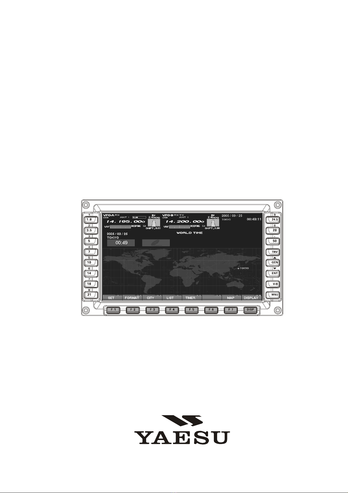
FTDX9000 TFT OPERATION MANUAL
When turning on the transceiver for the first time, please set the local time as soon as possible. If this is not
done, the various functions of the World Clock and Great Circle Map will not function correctly.
Note: If you wish to add a city to the City List that was programmed at the factory, you will need to supply your
own USB or PS2 Keyboard. If you utilize one of the pre-loaded cities, a keyboard is not necessary.
You may also set up the local time for other locations, without a keyboard, using the cities that have been pre-
loaded at the factory.
PLEASE READ THIS FIRST
1. Powering Up the Transceiver
On the rear panel, move the Power switch to the
“I” position to apply power from the power supply.
The transceiver will not turn on yet, but power will
now be supplied to the OCXO.
Hold in the front panel POWER switch to turn the
transceiver on.
Note: The opening screen will appear on the TFT
display, and the self-check function of the CPU in-
side the radio will begin. Then, the µ-Tuning circuitry
will receive the data from the CPU, and it will perform
its own self-check, and will preset itself to the proper
settings for the current operating frequency.
While the µ-Tuning circuitry is obtaining the data, the
drive mechanism will move from one end of its range
to the other end (fast), and this will cause a tempo-
rary “motor” noise that can be heard; this, does not
represent any trouble or problem.
When the radio is turned on for the first time, it takes
about 50 seconds (from turning the radio on to com-
pleting the self- check) until the radio becomes ready
to use; however, from the next time you turn it on, it
will take around 10 seconds until the transceiver is
ready for full operation.
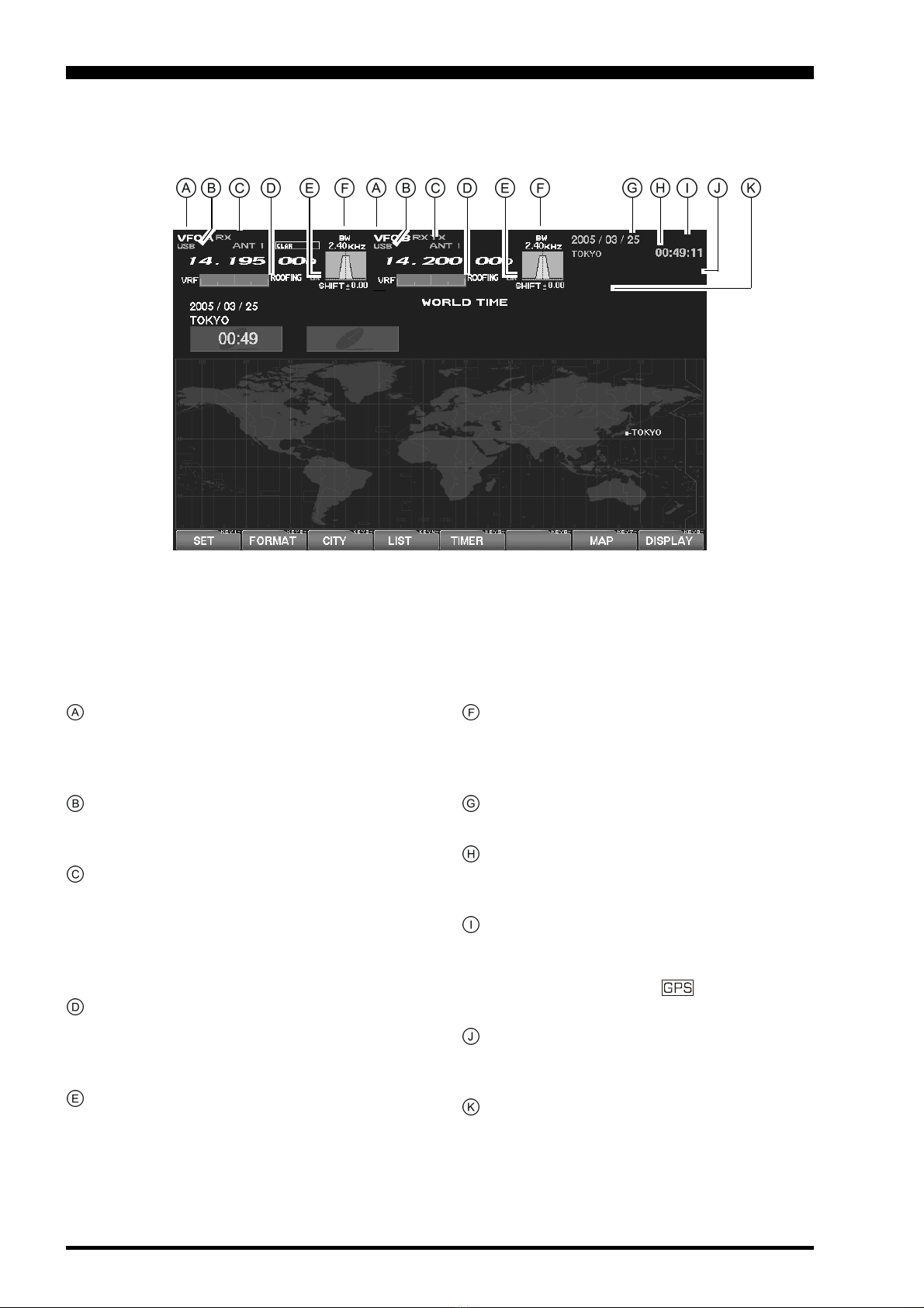
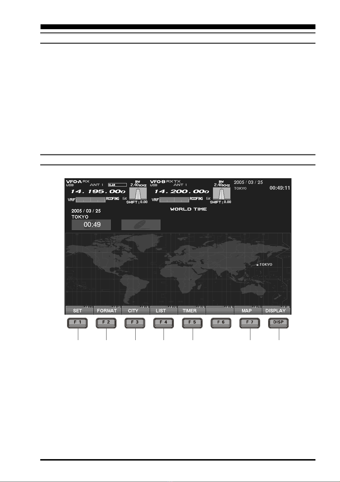
2. Local Time Setup
On the TFT, there should be a World Map dis-
played; if the World Map does not appear, find the
[DISP](Display)key below and to the right of the
TFT; press this key as many times as required to
get the World Map to display on the TFT.
Below the TFT, press the [F1](SET)key; the TFT
should now show LOCAL TIME -1; this setting
has been pre-set for Japanese time at the fac-
tory.
3. Changing the Location
To set the (highlighted) Time Zone, press the
[F7](SELECT)key to engage setting of the de-
sired Time Zone. Use the [F1]()~ [F4]()keys
to choose the Time Zone, then press the
[F7](SELECT)key once more.
The name of the country associated with the high-
lighted Time Zone may now be selected using the
[F1]()~ [F1]()keys. Press [F7](SELECT)when
you have made your selection.
You may now choose one of the cities displayed
in the same way. When you have made your
choice, press the [F7](SELECT)key.
Advice: Depending on the country, there may be only
one city (or no cities) listed. In these instances, to
modify the setting, please first select the city name
on the list, even if you do not see the city you want on
the list; you may modify the city name later.
4. Changing the City Name
(Please connect a PS/2 or USB Keyboard (not sup-
plied) to do manual entry of a city name. If you are
not entering a new city name, please skip to step (5)
below).
Use the [F1]()and [F2]()keys to highlight the
city name you wish to change. Now, press the
[F7](SELECT)key, then enter the name of the de-
sired city.
When you have completed your input, press the
[F7](SELECT)key once more.
5. Correcting the Date
Use the [F1]()and [F2]()keys to highlight
“DATE,” then press the [F7](SELECT)key.
Use the [F3]()and [F4]()keys to navigate to
each column of the date, then use the [F1]()
and [F2]()keys to select the desired numbers
in each column. Repeat for each column, to com-
plete the date.
When entry is complete, press the [F7](SELECT)
key.