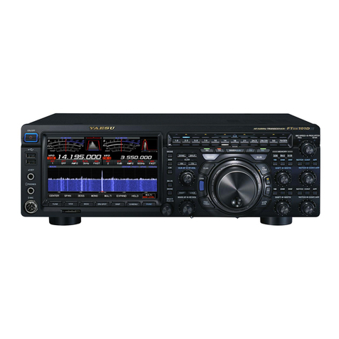
Yaesu FTdx5000 Series User manual

HF/50 MH
Z
T
RANSCEIVER
FT
DX
5000 S
ERIES
O
PERATING
M
ANUAL
VERTEX STANDARD CO., LTD.
4-8-8 Nakameguro, Meguro-Ku, Tokyo 153-8644, Japan
VERTEX STANDARD
US Headquarters
10900 Walker Street, Cypress, CA 90630, U.S.A.
YAESU UK LTD.
Unit 12, Sun Valley Business Park, Winnall Close
Winchester, Hampshire, SO23 0LB, U.K.
VERTEX STANDARD HK LTD.
Unit 5, 20/F., Seaview Centre, 139-141 Hoi Bun Road,
Kwun Tong, Kowloon, Hong Kong
VERTEX STANDARD (AUSTRALIA)PTY., LTD.
Normanby Business Park, Unit 14/45 Normanby Road
Notting Hill 3168, Victoria, Australia


Page 16 FTDX5000 OPERATING MANUAL
[POWER]Switch
Press and hold in this switch for two seconds to turn
the transceiver on, after first setting the rear panel
[MAIN POWER]switch to the “I” position. Press
and hold in this switch for two seconds, similarly, to
turn the transceiver off. If the rear panel [MAIN
POWER]switch is set to the “O” position, the front
panel [POWER]switch will not function.
ADVICE:
If you press this switch briefly while the transceiver
is turned on, the transceiver’s audio will be muted
for three seconds.
This is the actual power On/Off switch for turning
on the transceiver. When the rear panel [MAIN
POWER]switch is set to the “I” position, power
is supplied to the OCXO to stabilize the reference
oscillator, and the remainder of the transceiver is
set in a “stand-by” mode, awaiting the command
for the transceiver to switch on via the front panel
[POWER]switch. For further information on the
rear panel [MAIN POWER]switch, please see the
discussion on page ??.
CAT Indicator
This LED indicator will flash red when the transmit
and receive serial CAT command signals are being ex-
changed.
ADVICE:
You may disable the LED function (flashes in conjunc-
tion with CAT command) via Menu item “031 GEnE
CAT IND.” See page ??? for details.
PHONES Jack
A 1/4-inch, 3-contact jack accepts either monaural or
stereo headphones with 2- or 3-contact plugs. When a
plug is inserted, the loudspeaker is disabled. With ste-
reo headphones such as the optional YH-77STA, you
can monitor both VFO-A and VFO-B receiver chan-
nels at the same time during Dual Receive operation.
NOTE:
When wearing headphones, we recommend that you
turn the AF Gain levels down to their lowest settings
before turning power on, to minimize the impact on
your hearing caused by audio “pops” during switch-on.
KEY Jack
This 1/4-inch, 3-contact jack accepts a CW key or keyer
paddles (for the built-in electronic keyer), or output
from an external electronic keyer. Pinout is shown on
page 15. Key up voltage is 5 V, and key down current
is 1 mA. This jack may be configured for keyer, “Bug,”
“straight key,” or computer keying interface operation
via Menu item “054 A1A F-TYPE” (see page ???).
There is another jack with the same name on the rear
panel, and it may be configured independently for In-
ternal Keyer or pseudo-straight-key operation.
NOTE:
You cannot use a 2-contact plug in this jack (to do so
produces a constant “key down” condition).
Microphone Connector
This 8-pin jack accepts input from a microphone uti-
lizing a traditional YAESU HF-transceiver pinout.
FRONT PANEL CONTROLS & SWITCHES

Page 17FTDX5000 OPERATING MANUAL
[DIM]Switch
Press this button to lower the illumination intensity of
the analog meter and the frequency display. Press it
once more to restore full brightness.
ADVICE:
Menu Items “008 diSP DIM MTR” and “009 diSP
DIM VFD” allow you to configure the dimming lev-
els for the analog meter and the frequency display in-
dependently, so you can customize the brightness lev-
els.
[MOX]Switch
Pressing this button engages the PTT (Push to Talk)
circuit, to activate the transmitter (the LED inside this
button will glow red). It must be turned off (the red
LED will be off) for reception. This button replicates
the action of the Push to Talk (PTT) switch on the mi-
crophone. When engaging the [MOX]button (the LED
inside this button glows red) or otherwise causing a
transmission to be started, be certain you have either
an antenna or 50-Ohm dummy load connected to the
selected Antenna jack.
[VOX]Switch
This button enables automatic voice-actuated transmit-
ter switching in the SSB, AM, and FM modes. While
activated, the LED inside this button glows red. The
controls affecting VOX operation are the front panel’s
[VOX]and [DELAY]knobs. By proper adjustment of
these controls, hands-free voice-actuated operation is
possible.
[TUNE]Switch
This is the on/off switch for the FTDX5000’s Auto-
matic Antenna Tuner.
Pressing this button momentarily places the antenna
tuner in line between the transmitter final amplifier and
the antenna jack (“ ” icon will appear in the dis-
play). Reception is not affected.
Pressing and holding in this button for 1/2 second, while
receiving in an amateur band, activates the transmitter
for a few seconds while the automatic antenna tuner
rematches the antenna system impedance for minimum
SWR. The resulting setting is automatically stored in
one of the antenna tuner’s 100 memories, for instant
automatic recall later when the receiver is tuned near
the same frequency.
Pressing this button briefly, while the Tuner is engaged,
will take the Automatic Antenna tuner out of the trans-
mit line.
NOTE:
When the Automatic Antenna Tuner is tuning itself, a
signal is being transmitted. Therefore, be absolutely
certain that an antenna or dummy load is connected to
the selected antenna jack before pressing and holding
in the [TUNE]button to start antenna tuning.
[MONI](Monitor)Switch
This button enables the transmit monitor in all modes.
While activated, the “ ” icon appears in the dis-
play. Adjustment of the Monitor level is accomplished
using the [MONI]knob.
ADVICE:
When using headphones, the Monitor is highly useful
for making adjustments to the Parametric Equalizer or
other voice quality adjustments, because the voice qual-
ity heard in the headphones is such a “natural” repro-
duction of the transmitted audio quality.
[PROC](Processor)Switch
This button enables the Speech Processor for SSB
transmission. While activated, the “ ” icon appears
in the display. Adjustment of the Processor level is ac-
complished using the [PROC]knob.
ADVICE:
The Speech Processor is a tool for increasing the
average power output through a compression tech-
nique. However, if the [PROC]knob is advanced
too far, the increase in compression becomes
counter-productive, as intelligibility will suffer. We
recommend that you monitor the sound of your sig-
nal using the Monitor (with headphones).
When the optional DMU-2000 Data Management
Unit is connected, you may use the Audio Scope/
Oscilloscope page to help you adjust the setting of
the compression level of the Speech Processor for
optimum performance using your voice and micro-
phone.
[RX ANT]Switch
Press this button to use the RX ANT jack on the rear
panel while receive.
The “RX” icon appears in the display when the RX
ANT is used.
[ANT 1-4]Switch
Move this knob up and down to select one of the ANT
1 through 4 jack on the rear panel, and allows conve-
nient antenna switching at the move of knob. The se-
lected antenna jack is indicated in the ANT column of
the Block Diagram Display on the display.
ADVICE:
Press this knob briefly to select the ANT 1 jack for
quick selection.
FRONT PANEL CONTROLS & SWITCHES
Page 18 FTDX5000 OPERATING MANUAL
FRONT PANEL CONTROLS & SWITCHES
[ATT]Switch
Move this knob up and down to select the degree of
attenuation, if any, to be applied to the receiver input.
Available selections are “–6 dB”, “–12 dB”, “–18 dB”,
or “OFF”, and the selected attenuation level appears
in the ATT column of the Block Diagram Display on
the display.
ADVICE:
Press this knob briefly to select the attenuation level
to “OFF” for quick selection.
The Attenuator may be used in conjunction with
the [IPO]switch to provide two stages of signal
reduction when an extremely strong signal is being
received.
[IPO]
(I
NTERCEPT
P
OINT
O
PTIMIZATION
)
Switch
Move this knob up and down to select the optimum
front end characteristics of the receiver circuit for a
very strong-signal environment. Available selections
are “AMP 1”, “AMP 2”, “IPO 1”, or “IPO 2”.
Normally, this selection is set to “AMP1”. If you want
to increase the sensitivity, this selection selects to
“AMP2”. When this selection is set to “IPO1”, the IPO
is improved. When this selection is set to “IPO2”, by-
passes the RF preamplifier, yielding direct feed to the
first mixer. As a result, the IPO is improved more.
ADVICE:
Press this knob briefly to select the IPO setting to
“AMP1” for quick selection.
“IPO 2” selection can not selet in VFO-B.
[R.FLT]Switch
Move this knob up and down to select the bandwidth
for the first IF Roofing Filter. Available selections are
“300 Hz”, “600 Hz”, “3 kHz”, “6 kHz”, “15 kHz”, or
“AUTO” (“300 Hz” and “600 Hz” are select only in
VFO-A, additionally, “300 Hz” is option, except MP
version), and the selected bandwidth appears in the
R.FLT column of the Block Diagram Display on the
display.
ADVICE:
Press this knob briefly to select to “AUTO” for
quick selection.
Because the roofing filter is in the first IF, the pro-
tection it provides against interference is quite sig-
nificant. When set to “AUTO”, the SSB bandwidth
is 6 kHz, while CW is 3 kHz, and FM/RTTY are
15 kHz. On a crowded SSB band, however, you
may wish to select the 3 kHz filter, for the maxi-
mum possible interference rejection.

Page 19FTDX5000 OPERATING MANUAL
FRONT PANEL CONTROLS & SWITCHES
[AGC]Switch
Move this knob up and down to select the AGC char-
acteristics (receiver-recovery time) for the receiver.
Available selections are FAST, MID, SLOW, or AUTO,
and the selected receiver-recovery time appears at the
AGC column of the Block Diagram Display on the dis-
play.
Hold up or hold down this knob for two seconds to
disable the AGC (for testing or weak-signal reception).
ADVICE:
Press this knob briefly to select to AUTO for quick
selection.
If the AGC is set to disabled by holding up or down
the [AGC]knob, the S-meter will no longer de-
flect. Additionally, you will likely encounter dis-
tortion on stronger signals, as the IF amplifiers and
the following stages are probably being overloaded.
[METER]Switch
This control switch determines the function of the meter
during transmission.
COMP: Indicates the speech compressor level (SSB
mode only).
ALC: Indicates the relative ALC voltage.
PO: Indicates the average power output level.
SWR: Indicates the Standing Wave Ratio (Forward:
Reflected).
ID: Indicates the final amplifier drain current.
VDD: Indicates the final amplifier drain voltage.
[MONI] [PROC]Knobs
[MONI]Knob
The inner [MONI]knob adjust the audio level of
the transmit RF monitor during transmission (rela-
tive to the AF GAIN control), when activated by
the [MONI]button.
[PROC]Knob
The outer [PROC]knob sets the compression (in-
put) level of the transmitter Speech Processor in
the SSB, AM, and FM modes, when activated by
the [PROC]button.
ADVICE:
The SUB DISPLAY-
III
will show the relative com-
pression level of the Speech Processor for 3 sec-
onds whenever the outer [PROC]knob is turned.
You may disable this feature (displaying the rela-
tive compression level) via Menu item “015 diSP
LVL IND.” See page 113 for details.
(VFO-B)[NB][SQL]Knobs
[NB]Knob
The inner [NB]knob adjusts the VFO-B noise
blanking level when the (analog) IF noise blanker
is activated by pressing the [NB]button.
[SQL]Knob
The outer [SQL]knob sets the signal level thresh-
old at which the VFO-B receiver audio is muted, in
all modes. It is very useful during local rag-chews,
to eliminate noise between incoming transmissions.
This control is normally kept fully counter-clock-
wise (off), except when scanning and during FM
operation.
(VFO-A)[NB][SQL]Knobs
[NB]Knob
The inner [NB]knob adjusts the VFO-A noise
blanking level when the (analog) IF noise blanker
is activated by pressing the [NB]button.
[SQL]Knob
The outer [SQL]knob sets the signal level thresh-
old at which the VFO-A receiver audio is muted, in
all modes. It is very useful during local rag-chews,
to eliminate noise between incoming transmissions.
This control is normally kept fully counter-clock-
wise (off), except when scanning and during FM
operation.

Page 20 FTDX5000 OPERATING MANUAL
FRONT PANEL CONTROLS & SWITCHES
[MIC] [RF PWR]Knobs
[MIC]Knob
The inner [MIC]knob adjusts the microphone in-
put level for (non-processed) SSB transmission.
ADVICE:
If you adjust the MIC Gain while speaking in a
somewhat-louder-than-normal voice level,
watch the ALC level and adjust the MIC Gain
so that the ALC reaches just to the right edge of
the ALC scale. Then, when you speak in a more
normal voice level, you’ll be certain not to be
over-driving the mic amplifier stage.
The SUB DISPLAY-
III
will show the relative
Microphone Gain level for 3 seconds whenever
the inner [MIC]knob is turned.
You may disable this feature (displaying the rela-
tive Microphone Gain level) via Menu item “015
diSP LVL IND.” See page 113 for details.
[RF PWR]Knob
The outer [RF PWR]knob is the main RF Power
output control for the transceiver, active in all op-
erating modes. Clockwise rotation increases the
power output. Adjust this control for the desired
power output from the FTDX5000.
ADVICE:
The SUB DISPLAY-
III
will show the RF Power
Output for 3 seconds whenever the outer [RF
PWR]knob is turned.
You may disable this feature (displaying the RF
Power Output) via Menu item “015 diSP LVL
IND.” See page 113 for details.
[SPEED] [PITCH]Knobs
[SPEED]Knob
The inner [SPEED]knob adjusts the keying speed
of the internal CW keyer (4 ~ 60 WPM). Clock-
wise rotation increases the sending speed.
When turning this knob while pressing the
[KEYER]button, the Sub (VFO-B) frequency dis-
play shows the keying speed.
ADVICE:
The SUB DISPLAY-
III
will show the keying speed
for 3 seconds whenever the inner [SPEED]knob
is turned.
You may disable this feature (displaying the key-
ing speed) via Menu item “015 diSP LVL IND.”
See page ??? for details.
[PITCH]Knob
The outer [PITCH]knob selects your preferred CW
tone pitch (from 300 ~ 1050 Hz, in 50 Hz incre-
ments). The Tx sidetone, receiver IF passband, and
display offset from the BFO (carrier) frequency are
all affected simultaneously. The Pitch control set-
ting also affects the operation of the CW Tuning
Indicator, as the center frequency of the CW Tun-
ing Indicator will follow the setting of this control.
ADVICE:
The SUB DISPLAY-
III
will show the CW tone
pitch frequency for 3 seconds whenever the outer
[PITCH]knob is turned.
You may disable this feature (displaying the CW
tone pitch frequency) via Menu item “015 diSP
LVL IND.” See page ??? for details.

Page 21FTDX5000 OPERATING MANUAL
FRONT PANEL CONTROLS & SWITCHES
[VOX] [DELAY]Knobs
[VOX]Knob
The inner [VOX]knob sets the gain of the VOX
circuit, to set the level of microphone audio needed
to activate the transmitter during voice operation
while the [VOX]switch is engaged. The [VOX]
switch must be switched “ON” to engage the VOX
circuit.
[DELAY]Knob
The outer [DELAY]knob sets the hang time of the
VOX circuit for voice operation and keying delay
for CW operation.
During voice operation, this knob sets the hang time,
between the moment you stop speaking, and the
automatic switch from transmit back to receive.
Adjust this for smooth VOX operation, so the re-
ceiver is only activated when your transmission is
ended and you wish to receive.
For CW operation, this knob sets the keying delay,
between the moment you stop sending, and the au-
tomatic switch from transmit back to receive dur-
ing “Semi-break-in” operation. Adjust this just long
enough to prevent the receiver from being restored
during word spaces at your preferred sending speed.
ADVICE:
The SUB DISPLAY-
III
will show the hang time of
the VOX circuit for 3 seconds whenever the outer
[DELAY]knob is turned.
You may disable this feature (displaying the hang
time of the VOX circuit) via Menu item “015 diSP
LVL IND.” See page ??? for details.
(VFO-B)[AF GAIN][RF GAIN]Knobs
[AF GAIN]Knob
The inner [AF GAIN]knob sets the VFO-B
receiver’s audio volume level. Typically, you will
operate with this control set between the 9 o’clock
and 10 o’clock positions.
[RF GAIN]Knob
The outer [RF GAIN]knob is the VFO-B receiver’s
RF gain control, which adjusts the gain of the VFO-
B receiver’s RF and IF amplifier stages. This con-
trol is normally left in the fully clockwise position.
(VFO-A)[AF GAIN][RF GAIN]Knobs
[AF GAIN]Knob
The inner [AF GAIN]knob sets the VFO-A
receiver’s audio volume level. Typically, you will
operate with this control set between the 9 o’clock
and 10 o’clock positions.
[RF GAIN]Knob
The outer [RF GAIN]knob is the VFO-A receiver’s
RF gain control, which adjusts the gain of the VFO-
A receiver’s RF and IF amplifier stages. This con-
trol is normally left in the fully clockwise position.
[A], [B]Switches
Pressing the [A]or [B]button will illuminate the re-
spective indicator imbedded within the switch, allow-
ing adjustment of the major functions (such as mode
and band selection etc) on the VFO-A or VFO-B band.
Usually, the [A]button glow red, signifying that the
VFO-A is being adjusted. Similarly, pressing the [B]
button will cause its indicator glow orange, signifying
VFO-B adjustment.
ADVICE:
The [A]/[B]switch’s function is effect for following
switches:
y[RX ANT]switch
y[ANT 1-4]switch
y[ATT]switch
y[IPO]switch
y[R.FLT]switch
y[AGC]switch
y[NAR]switch
y[BAND]switches
y[MODE]switches
y[NB]switch
y[RX ANT]switch
QMB (Quick Memory Bank)Switches
[STO](Store)Button
Pressing this button copies operating information
(frequency, mode, bandwidth, and also repeater di-
rection/shift frequency and CTCSS functions on the
FM mode) into consecutive QMB Memories.
[RCL](Recall)Button
Pressing this button recalls one of up to five Quick
Memory Bank memories for operation.
[NAR](Narrow)Switch
This button is used to set the DSP (digital) filters to
narrow bandwidth. The default values are follows:
Ú:You may enable to adjust the bandwidth by the
[WIDTH]knob.
OFF
2.4 kHzÚ
(1.8 kHz - 4.0 kHz / 16 steps)
2.4 kHzÚ
(500 Hz - 2.4 kHz / 7 steps)
500 HzÚ
(500 Hz - 2.4 kHz / 7 steps)
500 HzÚ
(500 Hz - 2.4 kHz / 7 steps)
25 kHz
(±5.0 kHz Deviation)
9 kHz
25 kHz
(±5.0 kHz Deviation)
ON
1.8 kHzÚ
(200 Hz - 1.8 kHz / 9 steps)
500 HzÚ
(50 Hz - 500 Hz / 10 steps)
300 HzÚ
(50 Hz - 500 Hz / 10 steps)
300 HzÚ
(50 Hz - 500 Hz / 10 steps)
12.5 kHz
(±2.5 kHz Deviation)
6 kHz
12.5 kHz
(±2.5 kHz Deviation)
MODE
LSB/USB
CW
RTTY
(LSB)
PKT
(LSB/USB)
PKT
(FM)
AM
FM
NAR SWITCH

Page 22 FTDX5000 OPERATING MANUAL
FRONT PANEL CONTROLS & SWITCHES
[SPLIT]Switch
Pressing this button to activate split frequency opera-
tion between the VFO-A, used for reception, and the
VFO-B, used for transmission. If you press and hold
in this button for two seconds, the “Quick Split” fea-
ture will be engaged, whereby the VFO-B will auto-
matically be set to a frequency 5 kHz higher than the
VFO-A frequency with same operating mode, and the
transceiver will be placed in the Split mode.
[TXW](TX Watch)Switch
Pressing this button lets you monitor the transmit fre-
quency when split frequency operation is engaged.
Release the button to return to normal operation.
[CLASS-A]Switch
Pressing this button engages the Class-A capability for
the transmitter. The power output will be reduced to a
maximum of 75 Watts, however, the Class-A opera-
tion provides an ultra-clean SSB wave-form. When
Class-A operation is engaged, the “CLASS-A” icon
appears in the display. Press this button once more to
return to Class-AB operation at a maximum power
output of 200 Watts; the “CLASS-A” icon disappears
to confirm Class-AB operation.
ADVICE:
You may adjust the bias level between “Class-AB” and
“Class-A” via Menu item “015 tGEn BAIS”. See page
??? for details.
[C.S]Switch
Press this button briefly to recall a favorite Menu Se-
lection directly.
To program a Menu selection as the short-cut, press
the [MENU]button to enter the Menu, then select the
Menu item you want to set as the short-cut. Now press
and hold in the [C.S]button for two seconds; this will
lock in the selected Menu item as the short-cut.
(VFO-A)[RX]Indicator/Switch
This button, when pressed, engages the VFO-A re-
ceiver; the LED inside this button will glow green when
the VFO-A receiver is active.
When the VFO-A receiver is active, pressing this but-
ton briefly will mute the receiver, and the indicator will
blink. Pressing the button once more will restore re-
ceiver operation, and the indicator will glow green
steadily.
(VFO-A)[TX]Indicator/Switch
When this button is pressed, the LED inside this but-
ton will glow red, and the transmitter will be engaged
on the same frequency and mode as set up for the VFO-
A (subject to any Clarifier offset, of course).
ADVICE:
If this indicator is not illuminated, it means that the
VFO-B TX indicator has been selected (it will be glow-
ing red). In this case, transmission will be effected on
the frequency and mode programmed for the VFO-B.

Page 23FTDX5000 OPERATING MANUAL
FRONT PANEL CONTROLS & SWITCHES
Main Tuning Dial Knob
This large knob adjusts the operating frequency of the
VFO-A or a recalled memory. Clockwise rotation of
this knob increases the frequency. Default tuning in-
crements are 10 Hz (100 Hz in AM and FM modes);
when the [FAST]button is pressed, the tuning steps
increase. The available steps are:
ADVICE::
::
:
The tuning steps for the Main Tuning Dial knob are
set, at the factory, to 10 Hz per step. Via Menu item
“118 tun DIAL STEP,” however, you may change this
setting from 10 Hz to 5 Hz or 1 Hz instead. When press
the [FAST]button, the tuning step change to 100 Hz.
[FAST]Switch
Pressing this button will change the VFO-A’s tuning
step to 100 Hz.
When this function is activated, the “ ” icon ap-
pears in the display.
[LOCK]Switch
This button toggles locking of the Main Tuning Dial
knob, to prevent accidental frequency changes. When
the button is active, the Main Tuning Dial knob can
still be turned, but the VFO-A frequency will not
change, and the “ ” icon appears in the display.
[A
X
B]Switch
Press this button briefly to transfer data from the VFO-
A frequency (or a recalled memory channel) to the
VFO-B, overwriting any previous contents in the VFO-
B. Use this button to set both VFO-A and VFO-B re-
ceivers to the same frequency and mode.
[A
X
W
B]Switch
Pressing this button momentarily exchanges the con-
tents of the Main band (VFO-A) (or a recalled memory
channel) and the Sub band (VFO-B).
[V/M]Switch
This button toggles VFO-A receiver operation between
the memory system and the VFO. Either “ ” or
“” will be displayed to the under the main fre-
quency display field to indicate the current selection.
If you have tuned off of a Memory channel frequency
(MT), pressing this button returns the display to the
original memory contents (MR), and pressing it once
more returns operation to the VFO-A (no icon).
OPERATING MODE
LSB/USB/CW/RTTY/PKT(SSB)
AM/FM/PKT(FM)
Numbers in parentheses indicate steps when the [FAST]button is On.
1 STEP
10 Hz (100 Hz)
100 Hz (1 kHz)
1 DIAL ROTATION
10 kHz (100 kHz)
100 kHz (1 MHz)
[M
X
A]Switch
Pressing this button momentarily displays the contents
of the currently-selected memory channel for three sec-
onds.
Holding this button in for 2 seconds copies the data
from the currently-selected memory to the VFO-A, as
two beeps sound. Previous data in the VFO-A will be
overwritten.
[A
X
M]Switch
Pressing and holding in this button for 1/2 second (un-
til the double beep) copies the current operating data
from the VFO-A into the currently selected memory
channel, overwriting any previous data stored there.
See page ??? for details.
Also, pressing and holding in this button after recall-
ing a memory, without first retuning, causes the memory
channel to be “masked,” and repeating the process re-
stores the masked memory.
[MENU]Switch
This button is used for gaining access to the Menu sys-
tem, for configuring various transceiver characteris-
tics. Menu operation is described in detail, in this
manual, beginning on page ???.
IMPORTANT NOTE:
Pressing this button briefly activates the Menu, and
the Menu items will appear on the SUB DISPLAYs;
once you are finished, you must press and hold in the
[MENU]button for two seconds to save any configu-
ration changes (momentarily pressing the [MENU]
button to exit will not save the changes).
[BAND]Keys
These buttons allow one-touch selection of the desired
amateur band (1.8 ~ 50 MHz).
What’s more, these buttons may be used for direct en-
try of a desired operating frequency during VFO op-
eration.
[MODE]Switches
Pressing one of these buttons, selects the operating
mode. Repeated presses of a particular switch will
toggle to the alternate mode, or step through the avail-
able selections, as shown in the chart below.

Page 24 FTDX5000 OPERATING MANUAL
[NB]Switch
This button turns the IF Noise Blanker on and off.
Press this button briefly to reduce a short-duration pulse
noise; the “ ” icon will appear in the display.
Press and hold in this button for one second to reduce
a longer-duration man-made pulse noise; the “ W”
icon will appear in the display.
Press this button again to disable the noise blanker;
the “ ” or “ W” icon will disappear.
[KEYER]Switch
This button toggles the internal CW keyer on and off.
While activated, the “ ” icon appears in the dis-
play. The keyer sending speed is adjusted via the front
panel’s [SPEED]knob and the CW Hang Time is ad-
justed via the Menu item “044 A1A DELAY”.
ADVICE:
When press an holding this button to shows the keying
speed on the SUB DISPLAY-
III
.
You may disable this feature (displaying the keying
speed) via Menu item “015 diSP LVL IND.” See page
??? for details.
[SPOT]Switch
This button turns on the CW receiver spotting tone; by
matching the SPOT tone to that of the incoming CW
signal (precisely the same pitch), you will be “zero
beating” your transmitted signal on to the frequency of
the other station.
ADVICE:
The SUB DISPLAY-
III
will indicate the offset tone
frequency when this button is pressed.
[BK-IN]Switch
This button turns the CW break-in capability on and
off. While the CW break-in is activated, the “ ”
icon appears in the display.
[T(DOWN)]/[S(UP)] Switches
These buttons adjust the operating frequency of the
VFO or a recalled memory in 100 kHz step.
SUB DISPLAY-I
This LCD display shows the VFO-B frequency, and it
indicates the Menu List while the Menu Mode is ac-
tive.
FRONT PANEL CONTROLS & SWITCHES
Page 25FTDX5000 OPERATING MANUAL
[RX CLAR(FAST)] Switch
The function of this button is different by the setting of
the [A/B] button (described later).
When the imbedded LED of the [A/B]button is turned
off,pressing this button activates the RX Clarifier, to
allow offsetting the VFO-A receiving frequency tem-
porarily. Press this button once more to return the Main
receiver to the frequency shown on the main frequency
display field; the Clarifier offset will still be present,
though, in case you want to use it again. To cancel the
Clarifier offset, press the [CLEAR]button.
When the imbedded LED of the [A/B]button glows
orange, pressing this button will change the VFO-B’s
tuning step to 100 Hz.
When this function is activated, the “ ” icon ap-
pears in the display.
[CLEAR]Switch
Pressing this button clears out any frequency offset you
have programmed into the Clarifier register (thereby
setting the offset to “Zero”).
[TX CLAR/LOCK]Switch
The function of this button is different by the setting of
the [A/B] button (described later).
When the imbedded LED of the [A/B]button is turned
off,pressing this button activates the TX Clarifier, to
allow offsetting the VFO-A transmit frequency tempo-
rarily. Press this button once more to return the trans-
mitter to the VFO-A frequency shown on the main fre-
quency display field; the Clarifier offset will still be
present, though, in case you want to use it again. To
cancel the Clarifier offset, press the [CLEAR]button.
When the imbedded LED of the [A/B]button glows
orange, this button toggles locking of the
[CLAR(VFO-B)] knob, to prevent accidental fre-
quency changes. When this button is active, the
[CLAR(VFO-B)] knob can still be turned, but the
VFO-B frequency will not change, and the “ ”
icon appears in the display.
[CLAR/GRP]Switch
This button has two functions.
When press this button briefly, the [CLAR/VFO-B]
knob will be enabled for the purpose of unilizing the
[CLAR/VFO-B]knob as an “offset tuning” control to
allow tuning away from the VFO-A, and the imbedded
LED of the [CLAR/GRP]button is glows red.
When press and hold this button for one second, al-
lows you to select the memory group using the
[CLAR(VFO-B)] knob, and the imbedded LED of the
[CLAR/GRP]button is glows yellow.
[BAND(MCH)] Switch
This button has two functions.
When press this button briefly, allows you to select
the VFO-A operating band (Amateur bands) using the
[CLAR(VFO-B)] knob, and the LED inside of the
[CLAR/GRP)] button is glows red.
When press and hold this button for one second, al-
lows you to select the memory channel using the
[CLAR(VFO-B)] knob, and the imbedded LED of the
[CLAR/GRP]button is glows yellow.
[A/B]Switch
This button determines whether the actions of the
[CLAR(VFO-B)] knob will be applied to the VFO-A
or the VFO-B.
Pressing this button once causes the imbedded LED of
this button glows yellow; in this case, rotation of the
[CLAR(VFO-B)] knob affects operation on the VFO-
B (tuning, etc.). Pressing this button once more causes
the imbedded LED of this button to turn off; in this
instance, rotation of the [CLAR(VFO-B)] knob affects
operations associated with the VFO-A (Clarifier func-
tion, etc.).
(VFO-B)[RX]Indicator/Switch
This is the button that turns the VFO-B receiver “On”
and “Off”. When this button is pressed to make the
VFO-B receiver active, the imbedded LED will glows
green. Pressing this button again will disable this re-
ceiver, and the imbedded green LED will turn off.
(VFO-B)[TX]Indicator/Switch
This is the button that turns the VFO-B transmitter “On”
and “Off”. When this button is pressed to transfer trans-
mitter control to the VFO-B frequency and mode, the
imbedded LED will glows red. Pressing this button
once more will transfer frequency/mode control back
to theVFO-A side, and the red LED imbedded within
this button will turn off.
FRONT PANEL CONTROLS & SWITCHES
Page 26 FTDX5000 OPERATING MANUAL
[CLAR(VFO-B)]Knob
The function of this knob is different by the setting of
three switches located above this knob. See next page
for details.
SUB DISPLAY-II
This LCD display shows the character of the VFO-A
receiver’s DSP function selected by the five buttons
located below of this display, and the (VFO-
A)[SELECT]knob located below this window works
as an adjustment knob that displayed to this window.
Furthermore, when the Menu Mode is activated, this
LCD display indicates the Menu item.
(VFO-A)[VRF/-T]Switch
This button turns the VFO-A receiver’s contour filter
“on” and “off”, and allows you to adjust the center fre-
quency of the VRF filter by the (VFO-A)[SELECT]
knob. While activated, the red imbedded LED in this
button will light up, and the “ ” icon will appear in
the FLT column of the Block Diagram Display on the
display.
ADVICE:
When the optional RF Tuning Kit is connected, press-
ing this button will engage the -Tuning filter. The
Tuning Kit provides much better RF selectivity than
any other RF filter in the Amateur industry, yielding
outstanding protection from high RF levels not far re-
moved from the current operating frequency.
(VFO-A)[SHIFT]Switch
Pressing this button allows you to move the IF DSP
bandwidth of VFO-A “higher” or “lower” by the (VFO-
A)[SELECT]knob. When the IF passband is shifted,
the red LED imbedded in this button will light up. To
the contrary, when the IF passband is just centered, the
red LED imbedded in this button turns off.
(VFO-A)[CONT/APF]Switch
In the SSB, AM, and FM modes, this button turns the
VFO-A receiver’s contour filter “on” and “off”, and
allows you to adjust the center frequency of the con-
tour filter by the (VFO-A)[SELECT]knob. When the
contour filter is activated, the red imbedded LED in
this button will light up.
In the CW mode, this button turns the VFO-A receiver’s
APF (Audio Peak Filter) “on” and “off”, and allows
you to adjust the bandwidth of the APF filter by the
(VFO-A)[SELECT]knob. When the APF filter is ac-
tivated, the red imbedded LED in this button will light
up.
(VFO-A)[NOTCH]Switch
This button turns the VFO-A receiver’s IF notch filter
“on” and “off”, and allows you to adjust the center fre-
quency of the notch filter by the (VFO-A)[SELECT]
knob. When the notch filter is activated, the red im-
bedded LED in this button will light up.
FRONT PANEL CONTROLS & SWITCHES
Page 27FTDX5000 OPERATING MANUAL
FRONT PANEL CONTROLS & SWITCHES
Clarifier Operation
When the the [CLAR/GRP]button is pressed briefly,
the imbedded LED in the button will glow red, and the
[CLAR(VFO-B)] knob may be used to program an
offset of up to ± 9.999 kHz from the VFO-A frequency.
This offset is only applied, however, to the receive or
transmit frequency if the [RX CLAR/FAST]button
and/or [TX CLAR/LOCK]button, respectively, have
been pushed.
To apply the programmed frequency offset to the Re-
ceive frequency, press the [RX CLAR/FAST]button
briefly. To return to the VFO-A frequency, without the
offset, press the [RX CLAR/FAST]button once more.
To apply the programmed frequency offset to the Trans-
mit frequency, press the [TX CLAR/LOCK]button
briefly. To return the transmitter to the VFO-A fre-
quency, without the offset, press the [TX CLAR/
LOCK]button once more.
To reset the Clarifier frequency to “0” offset, press the
[CLEAR]button.
BAND Up / Down Control
When the [BAND/MCH]button is pressed briefly, the
imbedded LED in the button will glow red, and you
may enable the use of the [CLAR(VFO-B)] knob for
selecting the desired amateur band. If you have en-
gaged the “My Bands” feature via Menu #145, the
[CLAR(VFO-B)] knob will select from among just the
amateur bands that you have included in the “My
Bands” list.
Memory Channel / Memory Group Control
Pressing and holding in the [BAND/MCH]button for
two seconds, the imbedded LED in the button will glow
yellow, and you may enable the use of the
[CLAR(VFO-B)] knob for selection of the desired
Memory Channel.
Pressing and holding in the [CLAR/GRP]button for
two seconds, the imbedded LED in the button will glow
yellow, and you may enable the use of the
[CLAR(VFO-B)] knob for selecting the desired
Memory Group.
[CLAR(VFO-B)] Knob Functions
When the imbedded LED of the [A/B]button is turned “off”
In this case, the [CLAR(VFO-B)] knob is used for Clarifier tuning, as well as Up/Down selection of the Amateur
band, Memory Channels, 1 MHz tuning steps, or Memory Groups.
VFO-B FAST Tuning
When the [RX CLAR/FAST]button is pressed, the
“” icon appears in the display, and the VFO-B’s
tuning step changes to 100 Hz. Press the [RX CLAR/
FAST]button once more to return to the normal tun-
ing rate.
When the imbedded LED of the [A/B]button glows orange
When the [A/B]button is pressed, the imbedded LED in the button will glow orange, and the [CLAR(VFO-B)]
knob will now be exercising control functions associated with the VFO-B frequency control register.
VFO-B FAST Tuning
When the [TX CLAR/LOCK]button is pressed, the
“” icon appears in the display, and the the
[CLAR(VFO-B)] knob is locked. Press the [RX
CLAR/FAST]button once more to disable the lock
feature.
(VFO-A)[WIDTH]Switch
Pressing this button allows you to adjust the overall
bandwidth of the VFO-A receiver’s IF DSP filter by
the (VFO-A)[SELECT]knob. When the bandwidth
is set to different than the factory default, the red im-
bedded LED in this button will light up. To the con-
trary, when the bandwitdh is set to default, the red im-
bedded LED in this button turns off.
(VFO-A)[CLEAR]Switch
Pressing this button will reset to factory default the
function, which are selected with five buttons located
at the upper left of this button.
(VFO-A)[DNR]Knob
This button toggles the VFO-Areceiver’s Digital Noise
Reduction circuit “on” and “off”, and allows you to
adjust the noise reduction level by the (VFO-
A)[SELECT]knob. When the Digital Noise Reduc-
tion is activated, the red LED imbedded with in this
button will light up.
(VFO-A)[SELECT]Knob
This knob is used to adjust status of the functions se-
lected by the five buttons located above the knob.
(VFO-A)[DNF]Switch
This button toggles the VFO-Areceiver’s Digital Notch
Filter “on” and “off”. When the Digital Notch Filter is
activated, the red LED imbedded in this button will
light up. This is an automatic circuit, and there is no
adjustment knob for the DNF.

Page 28 FTDX5000 OPERATING MANUAL
SUB DISPLAY-III
This LCD display shows the character of the VFO-B
receiver’s DSP function selected by the five buttons
located below of this display, and the (VFO-
B)[SELECT]knob located below this window works
as an adjustment knob that displayed to this window.
Furthermore, when the Menu Mode is activated, this
LCD display indicates the current setting.
(VFO-B)[VRF]Switch
This button turns the VFO-B receiver’s contour filter
“on” and “off”, and allows you to adjust the center fre-
quency of the VRF filter by the (VFO-B)[SELECT]
knob. While activated, the orange imbedded LED in
this button will light up, and the “ ” icon will ap-
pear in the FLT column of the Block Diagram Display
on the display.
(VFO-B)[SHIFT]Switch
Pressing this button allows you to move the IF DSP
bandwidth of VFO-B “higher” or “lower” by the (VFO-
B)[SELECT]knob. When the IF passband is shifted,
the orange LED imbedded in this button will light up.
To the contrary, when the IF passband is just centered,
the red LED imbedded in this button turns off.
(VFO-B)[CONT/APF]Switch
In the SSB, AM, and FM modes, this button turns the
VFO-B receiver’s contour filter “on” and “off”, and
allows you to adjust the center frequency of the con-
tour filter by the (VFO-B)[SELECT]knob. When the
contour filter is activated, the orange imbedded LED
in this button will light up.
In the CW mode, this button turns the VFO-B receiver’s
APF (Audio Peak Filter) “on” and “off”, and allows
you to adjust the bandwidth of the APF filter by the
(VFO-B)[SELECT]knob. When the APF filter is ac-
tivated, the orange imbedded LED in this button will
light up.
(VFO-B)[NOTCH]Switch
This button turns the VFO-B receiver’s IF notch filter
“on” and “off”, and allows you to adjust the center fre-
quency of the notch filter by the (VFO-B)[SELECT]
knob. When the notch filter is activated, the orange
imbedded LED in this button will light up.
(VFO-B)[WIDTH]Switch
Pressing this button allows you to adjust the overall
bandwidth of the VFO-B receiver’s IF DSP filter by
the (VFO-B)[SELECT]knob. When the bandwidth
is set to different than the factory default, the orange
imbedded LED in this button will light up. To the con-
trary, when the bandwitdh is set to default, the orange
imbedded LED in this button turns off.
FRONT PANEL CONTROLS & SWITCHES

Page 29FTDX5000 OPERATING MANUAL
FRONT PANEL CONTROLS & SWITCHES
(VFO-B)[CLEAR]Switch
Pressing this button will reset to factory default the
function, which are selected with five buttons located
at the upper left of this button.
(VFO-B)[DNR]Knob
This button toggles the VFO-B receiver’s Digital Noise
Reductio””n circuit “on” and “off”, and allows you to
adjust the noise reduction level by the (VFO-
B)[SELECT]knob. When the Digital Noise Reduc-
tion is activated, the orange LED imbedded with in
this button will light up.
(VFO-B)[SELECT]Knob
This knob is used to adjust status of the functions se-
lected by the five buttons located above the knob.
(VFO-A)[DNF]Switch
This button toggles the VFO-Areceiver’s Digital Notch
Filter “on” and “off”. When the Digital Notch Filter is
activated, the orange LED imbedded in this button will
light up. This is an automatic circuit, and there is no
adjustment knob for the DNF.

Page 30 FTDX5000 OPERATING MANUAL
(VFO-A)Block Diagram Display
ANT (1, 2, 3, 4, RX):
Indicates the antenna selected for operation by the front
panel [ANT 1-4]and [RX ANT]switches.
ATT (OFF, –6 dB, –12 dB, –18 dB):
Indicates the attenuation level selected for operation
by the front panel [ATT]button.
FLT (VRF, -TUNE, THRU):
Indicates the RF filter selected for operation by the
front panel (VFO-A)[VRF/-T]button.
ADVICE:
The -TUNE filter is an option. The “ ” icon will
not appear when the optional -TUNE unit is not con-
nected.
IPO (AMP1, AMP2, IPO1, IPO2):
Indicates the front end RF amplifier selected for op-
eration by the front panel [IPO]button.
R.FLT (300, 600, 3k, 6k, 15k):
Indicates the 1st IF Roofing Filter selected for opera-
tion by the front panel [R.FLT]button.
ADVICE:
The 300 Hz Roofing Filter is an option except the MP
version. The “300” icon will not appear when the op-
tional 300 Hz Roofing Filter is not installed.
AGC (AUTO, FAST, MID, SLOW):
Indicates the AGC decay time selected for operation
by the front panel [AGC]switch.
(VFO-A)Status Indicator
:
This indicator appears during transmission on the VFO-
A frequency.
:
This indicator appears whenever the VFO-A receiver
squelch is open. If this indicator is not showing, and
reception seems to have been lost on the VFO-A re-
ceiver for no apparent reason, check the position of
the (VFO-A)[SQL]knob and rotate it fully counter-
clockwise to restore reception.
:
This indicator appears when the Main Tuning Dial
knob’s tuning rate is selected to fast.
:
This indicator appears when the Main Tuning Dial knob
is locked.
, , , , , ,
Displays the currently-selected operating mode for the
VFO-A.
This indicator appears whenever the VFO-A receiver’s
narrow IF DSP filter is engaged.
The “ ” icon appears when the VFO-A receiver’s
(short duration) Noise Blanker is activated.
The “ ” icon appears when the VFO-Areceiver’s
(longer-pulse) Noise Blanker is activated.
DISPLAY INDICATIONS (LEFT SIDE)

Page 31FTDX5000 OPERATING MANUAL
(VFO-B)Block Diagram Display
ANT (1, 2, 3, 4, RX):
Indicates the antenna selected for operation by the front
panel [ANT 1-4]and [RX ANT]switches.
ATT (OFF, –6 dB, –12 dB, –18 dB):
Indicates the attenuation level selected for operation
by the front panel [ATT]button.
FLT (VRF, THRU):
Indicates the RF filter selected for operation by the
front panel (VFO-A)[VRF]button.
ADVICE:
The -TUNE filter is an option. The “ ” icon will
not appear when the optional -TUNE unit is not con-
nected.
IPO (AMP1, AMP2, IPO1, IPO2):
Indicates the front end RF amplifier selected for op-
eration by the front panel [IPO]button.
R.FLT (3k, 6k, 15k):
Indicates the 1st IF Roofing Filter selected for opera-
tion by the front panel [R.FLT]button.
AGC (AUTO, FAST, MID, SLOW):
Indicates the AGC decay time selected for operation
by the front panel [AGC]switch.
This indicator appears whenever the Digital Noise Re-
duction feature is activated.
(VFO-B)Receiver S-Meter
Displays the strength of signals received on the VFO-
B.
(VFO-B)Status Indicator
:
This indicator appears during transmission on the VFO-
B frequency.
:
This indicator appears whenever the VFO-B receiver
squelch is open. If this indicator is not showing, and
reception seems to have been lost on the VFO-B re-
ceiver for no apparent reason, check the position of
the (VFO-B)[SQL]knob and rotate it fully counter-
clockwise to restore reception.
:
This indicator appears when the [CLAR(VFO-B)]
knob’s tuning rate is selected to fast.
:
This indicator appears when the [CLAR(VFO-B)]
knob is locked.
, , , , , ,
Displays the currently-selected operating mode for the
VFO-B.
This indicator appears whenever the VFO-B receiver’s
narrow IF DSP filter is engaged.
The “ ” icon appears when the VFO-B receiver’s
(short duration) Noise Blanker is activated.
The “ ” icon appears when the VFO-B receiver’s
(longer-pulse) Noise Blanker is activated.
DISPLAY INDICATIONS (LEFT SIDE)

Page 32 FTDX5000 OPERATING MANUAL
This indicator appears whenever the transmit monitor
circuit is activated.
This indicator appears whenever the internal CW keyer
is activated.
This indicator appears whenever CW break-in opera-
tion is activated.
This indicator appears whenever the DSP Speech Pro-
cessor is activated.
This indicator appears when the internal Automatic An-
tenna Tuner is activated.
This indicator appears if the directional coupler and
microprocessor detect an abnormally high SWR con-
dition (over 3.0:1) that cannot be resolved by the Au-
tomatic Antenna Tuner.
NOTE:
If this indicator appears, check to be sure that you have
the correct antenna selected on the current operating
band. If so, you will need to check the condition of the
antenna, its coaxial cable, and/or the connectors on the
cable so as to locate and correct the fault.
VFO-A Frequency Display
This is the VFO-A frequency display.
This indicator appears while the voice recorder is play-
ing back the recorded audio, and/or the memory is play-
ing back the recorded CW or voice message.
This indicator appears while the voice recorder is re-
cording the receiver audio, and/or the memory is re-
cording your CW or voice message.
This indicator appears whenever the Three-Band Para-
metric Microphone Equalizer is activated via the Menu.
This indicator appears when Class-A operation is en-
gaged.
Tuning Offset Indicator
This is a tuning scale that, as configured from the fac-
tory, provides a visual CW tuning indication of the in-
coming signal’s offset from your transceiver’s CW car-
rier frequency, as programmed by the relative clarifier
offset, or the peak position of the VRF/-TUNE filter.
CLAR
This indicator appears whenever the Clarifier function
is activated.
This indicator appears when the transceiver is in the
Memory Recall mode.
This indicator appears when the transceiver is in the
Memory Tune mode to indicate that the memory con-
tents have been temporarily changed.
DISPLAY INDICATIONS (RIGHT SIDE)

Page 33FTDX5000 OPERATING MANUAL
REAR PANEL CONNECTIONS
IF OUT Jacks
This RCA output jack is used for connection to the
optional SM-5000 Station Monitor.
ANT 1, 2, 3, 4 Jacks
Connect your main antenna(s) here, using a type-M
(PL-259) plug and coaxial feedline for each. These an-
tenna ports are always used for transmission, and also
are used for reception unless a separate receive an-
tenna is also used for the receiver. The internal antenna
tuner affects only the antenna(s) connected here, and
only during transmission.
RX ANT IN Jack
The BNC jack provides output of the receiver signal
lines from the Antenna jacks which are connected to
“RX” side of the transceiver’s main T/R switching cir-
cuitry.
The type-M jack is for a separate receive-only antenna.
An antenna connected here can be used when the [RX
ANT]button on the front panel is pressed.
If you want to use some special kind of external
bandpass filter or preamplifier, you may connect it
between the “RX ANT OUT” and “RX ANT IN” jacks.
GND
Use this terminal to connect the transceiver to a good
earth ground, for safety and optimum performance. Use
a large diameter, short braided cable for making ground
connections, and please refer to page 9 for other notes
about proper grounding.
-TUNE Jacks
These jacks are used for signal input/output of the op-
tional RF Tuning Kit.
ROTATOR Jack
This 6-pin MINI-DIN Jack accepts a cable connected
to a YAESU G-800DXA/-1000DXA/-2800DXA An-
tenna Rotator (listed models are current as of early
2010). You may control the antenna azimuth rotation
(and rotation speed) using the Function buttons on the
front panel.
BAND DATA Jack
This 8-pin output jack provides band selection data
which may be used for control of optional accessories
such as the VL-1000 Solid-state Linear Amplifier.
PACKET Jack
This 5-pin input/output jack provides receiver audio
and squelch signals, and accepts transmit (AFSK) au-
dio and PTT control, from an external Packet TNC.
Pinout is shown on page 15. The receiver audio level
at this jack is approximately 100 mVp-p (@600 Ohms).
RTTY Jack
This 4-pin input/output jack provides connections for
an RTTY terminal unit. Pinout is shown on page 15.
The receiver audio level at this jack is at a constant
100-mV (@600 Ohms) level. FSK keying at this jack
is accomplished by a closure of the SHIFT line to
ground by the terminal unit.
Other manuals for FTdx5000 Series
3
Table of contents
Other Yaesu Transceiver manuals

Yaesu
Yaesu FT-950 Technical manual

Yaesu
Yaesu FT-2500M Manual

Yaesu
Yaesu FT-207R User manual

Yaesu
Yaesu FTM-400DR/DE Manual

Yaesu
Yaesu FT-857D User manual

Yaesu
Yaesu FTM-350 - APRS User manual

Yaesu
Yaesu FT-60R/E Manual

Yaesu
Yaesu FT-757GX II User manual

Yaesu
Yaesu FT-710 Use and care manual

Yaesu
Yaesu VX-7R User manual

Yaesu
Yaesu PEP2000 - UPDATE V0150 AND V11.53 Technical manual

Yaesu
Yaesu FT-710 User manual

Yaesu
Yaesu FTC-4610 Manual

Yaesu
Yaesu FT-891 User manual

Yaesu
Yaesu FTA-850L User manual

Yaesu
Yaesu FT-212RH Manual

Yaesu
Yaesu FT-1802M User manual

Yaesu
Yaesu GX1280S User manual

Yaesu
Yaesu 600 User manual

Yaesu
Yaesu FT-One User manual