Yaesu FTDX101D User manual

Operation Manual


1
About this Manual
The FTDX101D is a leading-edge transceiver with a number of new and exciting features, some of which
may be unfamiliar to you. In order to gain the most enjoyment and operating efficiency from the FT-
DX101D, we recommend that you read this manual in its entirety, and keep it handy for reference as you
explore the many capabilities of this new transceiver.
Before using the FTDX101D, be sure to read this manual.
How to read this operation manual
Two methods are used to select an item displayed on the FTDX101 Function Screen: “Operate by
touching the item directly on the display”;and “Turn the [MULTI] knob to select the item and then
press the [MULTI] knob”.
Subsequently, in this manual, the operations that can be performed either by touching the Function
Screen, or by turning and pressing the [MULTI] knob are abbreviated to “Select [DISPLAY SETTING] →
[DISPLAY] → [TFT DIMMER]”; as described in the following:
Example: How to adjust the brightness of the display
1. Press the [FUNC] key to display the function screen.
2. Touch [DISPLAY SETTING] on the function screen, or rotate the [MULTI] knob to select [DISPLAY
SETTING] and then press the [MULTI] knob.
3. Touch [DISPLAY] on the display or rotate the [MULTI] knob to select [DISPLAY] and then press the
[MULTI] knob.
4. Touch the setting section of [TFT DIMMER] on the display, or rotate the [MULTI] knob to select [TFT
DIMMER] and then press the [MULTI] knob.
5. Rotate the [MULTI] knob to adjust the brightness.
The following notations are also used in this manual:
This icon indicates cautions and alerts the user should be aware of.
This icon indicates helpful notes, tips and information.

2
Table of Contents
General Description........................................4
Safety Precautions .........................................6
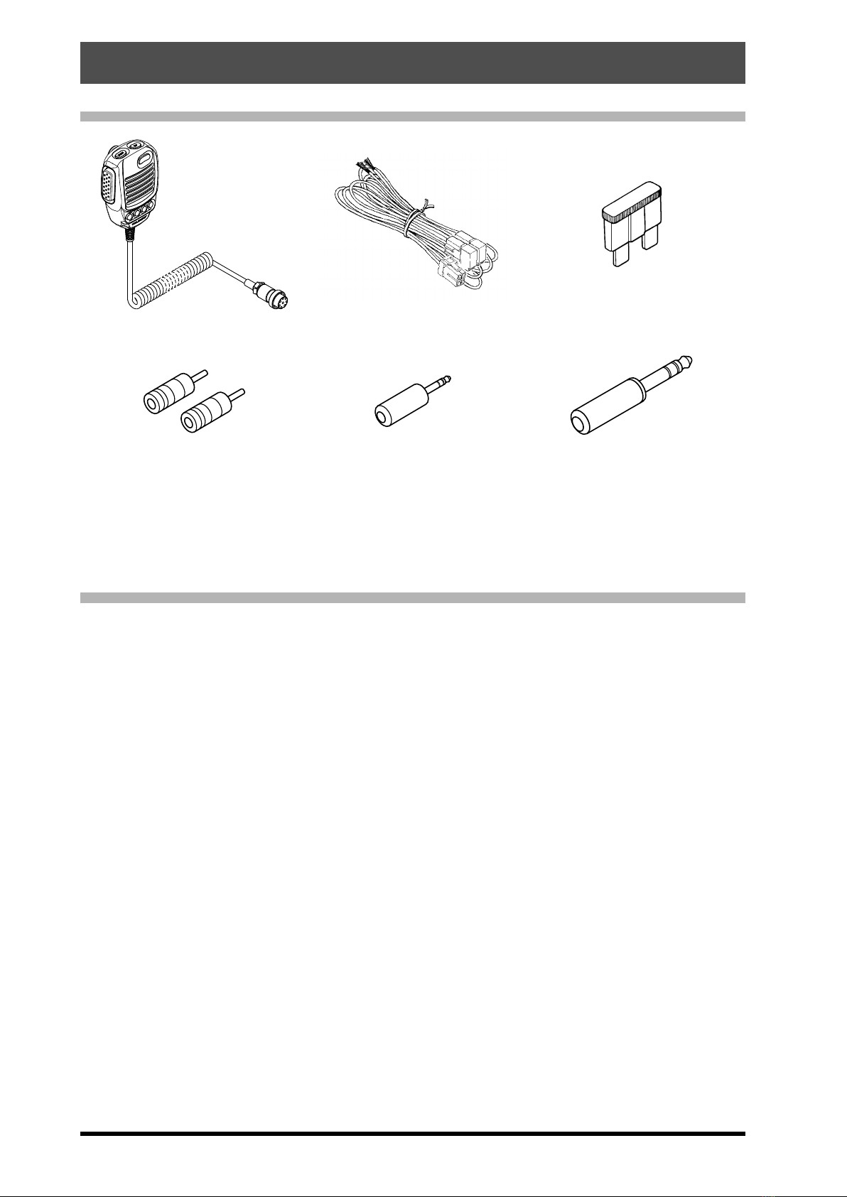
Accessories & Options ...................................8
Supplied Accessories ........................................ 8
Available options ............................................... 8
Installation and Interconnections....................9
Antenna Considerations .................................... 9
Antenna and Power Cable Connections ........... 9
Microphone, Headphone, Key, Keyer
and FH-2 Connections .................................... 10
Linear Amplier Interconnections .................... 11
VL-1000 Linear Amplier Interconnections.. 11
Interfacing to Other Linear Ampliers .......... 11
Rear Panel....................................................12
SSM-75G Microphone Switches...................14
Be sure to study this information to
maximize the receiver performance
of the high-class FTDX101D shortwave
transceiver. ...................................................15
Display Indications........................................16
Meter Display .................................................. 16
Filter Function Display..................................... 17
Display only DSP lter
bandwidth information ................................. 17
Frequency Display........................................... 17
Keyboard Frequency Entry.......................... 17
Tuning in 1 MHz or 1 kHz Steps.................. 17
Important Receiver Settings ............................ 18
ANT (Switching the Antenna) .......................... 18
ATT (Attenuator) .............................................. 18
IPO ................................................................. 18
R.FIL (
Roong Filter Switching
).......................... 19
AGC (
Automatic Gain Control
).......................... 19
Scope Display Setting ..................................... 20
CENTER...................................................... 20
CURSOR..................................................... 20
FIX............................................................... 21
SPEED ........................................................ 23
PEAK........................................................... 23
MARKER ..................................................... 23
COLOR........................................................ 23
LEVEL ......................................................... 23
Other On-Screen Indications........................... 25
Screen Saver................................................... 26
Adjust contrast................................................. 26
Adjusting the brightness .................................. 26
(Dimmer) ......................................................... 26
Font setting for ............................................... 26
frequency display ............................................ 26
Inputting the Call Sign ..................................... 26
Front Panel Controls & Switches..................28
Adjusts the VOX GAIN ................................ 29
Adjusts the VOX Delay Time ....................... 29
Adjusts the VOX anti-trip sensitivity ............ 29
QMB Channel Storage ................................ 31
QMB Channel Recall................................... 31
Conrm the contents of QMB ...................... 31
Changing the number of ............................. 31
QMB channels............................................. 31
Mark the operation band ............................. 31
Quick Split Operation .................................. 33
Direct input of offset frequency.................... 33
Clarier ............................................................ 35
RX Clarier ................................................. 35
Adjust transmit frequency to the
offset frequency........................................... 35
TX Clarier .................................................. 35
To offset the frequency with the
TX Clarier Adjust receive frequency .......... 35
VC TUNE......................................................... 36
Fine tune the tuning point............................ 36
C.S (Custom Select)........................................ 36
How to assign functions .............................. 36
MAIN/SUB ....................................................... 36
Switching the operation of the
[RF/SQL] knob............................................. 38
MAIN Band Operation ..................................... 40
Adjusting the Noise Attenuation .................. 40
Reduces longer duration pulse noise.......... 40
Set the MULTI knob to NB level
adjustment knob .......................................... 40
Adjust the GAIN of the CONTOUR Circuit .. 42
Sets the Bandwidth (“Q”) of the
CONTOUR Circuit ....................................... 42
Voice Communications (SSB and AM) .........46
When transmitting in SSB or AM mode ........... 46
Speech Processor ........................................... 47
RF Power output control.................................. 47
Parametric Microphone Equalizer ................... 48
Setup the Parametric
Microphone Equalizer.................................. 48
Activate the Parametric
Microphone Equalizer.................................. 48
Voice Memory.................................................. 50
Recording Your Own Voice in Memory........ 50
Checking the Recording .............................. 50
Transmitting the Recorded Message .......... 50
Adjustable Receiver Audio Filter ..................... 51
Using the Automatic Antenna Tuner ................ 52
ATU Operation............................................. 52

3
CW Mode Operation.....................................54
Adjusting the Sidetone Audio level .............. 54
CW Delay Time Setting ............................... 54
CW Decode ..................................................... 55
CW Spotting (Zero-Beating) ............................ 55
Setting of the Electronic Keyer ........................ 56
Adjusting the Keyer Speed.......................... 56
Setting the Keyer Weight (Dot/Dash) Ratio
... 56
Reversing the Keyer Polarity....................... 56
Selecting the Keyer Operating Mode .......... 56
Contest Memory Keyer.................................... 57
Message Memory........................................ 57
Storing a Message into Memory.................. 57
Message Memory Programming
(Using your Paddle)..................................... 57
Checking the CW Memory Contents ........... 58
On-The-Air CW Message Playback ............ 58
TEXT Memory ............................................. 59
Text Memory Storage .................................. 59
Text Message Programming........................ 59
Checking the CW Memory Contents ........... 60
On-The-Air CW Message Playback ............ 60
FM Mode Operation......................................61
Repeater Operation......................................... 61
Tone Squelch Operation.................................. 61
RTTY (FSK) Operation .................................62
Connecting to a Personal Computer ............... 62
Connecting to the TU (Terminal Unit) .............. 62
RTTY Decode.................................................. 63
RTTY Text Memory.......................................... 64
Text Message Programming on
TFT Screen ................................................. 64
Text Message Programming on
FH-2 Remote Controller .............................. 64
Text Input..................................................... 64
On-The-Air RTTY Text Message Playback.. 64
DATA (PSK) Operation .................................65
Connecting to a Personal Computer ............... 65
Connecting to the Data Communications
Device ............................................................. 65
PSK Decode.................................................... 66
PSK Text Memory............................................ 67
Text Message Programming on
TFT Screen ................................................. 67
Text Message Programming on
FH-2 Remote Controller .............................. 67
Text Input..................................................... 67
On-The-Air PSK Text Message Playback.... 67
Memory Operation........................................68
Memory Storage.......................................... 68
Erasing Memory Channel Data ................... 68
Check Memory Channel Status................... 69
Recall a Memory Channel other than
the last used VFO frequency....................... 69
Memory Tune Operation.............................. 69
Moving Memory Data to the VFO register... 70
Labeling Memories ...................................... 70
Displaying the Memory Tag ......................... 70
Scan Skip Setting ........................................ 70
Memory Groups............................................... 71
Choosing the Desired Memory Group............. 71
VFO and Memory Scanning .........................72
VFO/Memory Scan.......................................... 72
Programmable Memory Scan (PMS) .............. 73
Other Functions............................................74
Band Stack Operation ..................................... 74
TOT (Time Out Timer) ..................................... 74
[MULTI] knob Step Increment Setting.............. 74
Operation on Alaska Emergency Frequency:
5167.5 kHz (U.S. Version Only) ...................... 75
Screen capture ................................................ 75
Using the SD Card .......................................... 76
SD Cards that can be used ......................... 76
Installing the SD card .................................. 76
Removing the SD card ................................ 76
Formatting a SD card .................................. 76
Saving Memory data and Setting
Menu data ................................................... 77
Reading Memory and Set Menu data.......... 78
Display the SD Card Information................. 78
Setting Menu ................................................79
Using the Menu ............................................... 79
Resetting the Microprocessor.....................107
Optional Accessories..................................108
FC-40 External Automatic Antenna Tuner
(for Wire Antenna) ......................................... 108
Interconnections to FTDX101D ................. 108
Setup the FTDX101D ................................ 109
Optional FH-2 Control ................................... 110
Specications ............................................. 111
General...........................................................111
Transmitter .....................................................111
Receiver ........................................................ 112
Index........................................................... 113
YAESU LIMITED WARRANTY................... 116

4
General Description
Hybrid SDR conguration
In addition to the narrow band SDR receiver that boasts awesome basic performance, the FTDX101D has
a hybrid SDR conguration utilizing an integrated direct sampling SDR receiver, which permits visualiza-
tion of the spectrum of the entire band in real time.
By adopting the hybrid SDR method, and utilizing the features of the direct sampling method, wide-view
displays of the information in the entire band in real time, and improved performance of the entire receiv-
ing circuit with the narrow band SDR technology down conversion method are possible.
Comes equipped with three types of roong lters
This transceiver is equipped with three types of roong lters for 600 Hz, 3 kHz and 12 kHz bandwidths.
These narrow band lters are especially useful on a very crowded band during contests, because they
can dramatically attenuate powerful out-of-band signals in the rst IF stage, and thus reduce their impact
in the second stage. Further, the excellent dynamic range and IP3 characteristics optimize the processing
of all signals ranging from faint to powerful.
Adopts 3DSS/Hybrid Dual SDR Display
In addition to the conventional waterfall display, a 3DSS (3 Dimensions Spectrum Stream) image method
has been newly adopted. The 3DSS image uses the horizontal axis (X axis) for frequency, the vertical
axis (Y axis) for signal intensity, and the Z axis for time. Compared to the conventional waterfall method,
the signal strength is displayed in three dimensions as well as in color, recognition of changes in the band
conditions is instant, convenient and intuitive.
The 3DSS waterfall display has a choice of the mono display that displays only the MAIN frequency band;
or the dual display that illustrates both the MAIN and SUB frequency bands.
The Hybrid Dual SDR Display presents two SDR outputs, narrow band SDR and direct sampling SDR,
combined the same screen. Since the display color of each SDR output can be changed, the band re-
ceived by the narrow band SDR receiver can be viewed while also observing the condition of the entire
band.
High-brightness TFT full-color display with touch-panel functionality
The FTDX101D is equipped with a 7-inch full-color TFT display. Operating functions, including the receiv-
ing band noise and signal interference reduction tools, are graphically displayed. Even while involved in
rigorous operations, such as DXpeditions and contests, the operator may instantly grasp the status of
each function.
Filter Function Display monitors the status of the passband
In the upper part of the display, an S meter and a lter function display present the state of the pass-band.
They are arranged independently for the MAIN Band and SUB Band respectively. In addition to the oper-
ating state of the interference removal functions, the lter function information is displayed. Not only can
you grasp the operating status of WIDTH, SHIFT, NOTCH and CONTOUR at a glance, you can also view
the status of the RF spectrum in the passband.
RF Pre-selector, Continuously Variable RF, & VC-TUNE
The newly developed VC tuning circuit drives a variable capacitor with a high-precision stepping motor
and is comparable with a µ-Tuning mechanism, it achieves remarkable interference reduction character-
istics with signicant downscaling and maximum attenuation of -70 dB. When compared with the conven-
tional preset method, which switches a coil and a capacitor with a relay, the high-precision stepping motor
continuously follows the frequency inside the pass-band, there is no sense of discomfort as there is with
relay switching. Even when there are multiple powerful signals in the band, ne adjustment to the optimal
tuning point is possible.
Two selectable RF Stages amplify the desired signals from low band to
high band
Push-pull RF amplier AMP1, and AMP2 are low noise negative feedback RF ampliers that may be se-
lected or combined in series as is needed for various low-band, high-band, frequency and noise conditions.
In addition, the IPO (Intercept Point Optimization) function maximizes the dynamic range and enhances
the close multi-signal and inter-modulation characteristics of the receiver. The inuence of strong broad-
casting stations, especially in the low bands, can be minimized.

5
WIDTH and the continuously variable Bandwidth SHIFT features per-
mit elimination of interfering signals
The WIDTH feature allows the bandwidth to be narrowed by rotating the WIDTH knob. The SHIFT feature,
can eliminate interference in one side of the passband. Often, weak signals disappear due to interfering
signals (including pile-ups). The interfering signals may be extracted, leaving only the desired signal, be-
cause of the unique DSP sharp ltering characteristics.
CONTOUR feature is renowned for effective noise reduction
Rather than using the DSP extremely sharp attenuation characteristics, the CONTOUR circuit provides
gentle shaping of the DSP passband lter, and can thus attenuate or peak bandwidth components in seg-
ments. The interfering signal can be naturally shaped without having part of the signal suddenly disrupted.
The contour function is very effective in making the desired signal rise out of the interference.
DNR (Digital Noise Reduction) by DSP digital processing
The incorporated digital noise reduction circuit may be set to the optimal working algorithm by varying the
15 step parameters according to the noise type.
NOTCH feature can eliminate an unwanted heterodyne, and the DNF
feature can instantly attenuate multiple heterodyne signals
When interfering beat signals are present in the receiver passband, the IF NOTCH feature can signicant-
ly eliminate a narrow portion of the passband and remove the interfering signal. Moreover, when there are
multiple interfering signals, the DSP DNF (Digital Notch Filter) Automatic Tracking System can be effec-
tive, even when an interfering frequency is changing.
ABI (Active Band Indicator)
Band keys are arranged in a row at the top above the main dial so that the operation status of the MAIN
and SUB Bands can be checked at a glance. The band selected on the MAIN side is white, the band se-
lected on the SUB side is blue. The white and blue correspond to the colors of the MAIN and SUB Band
Switches.
When transmitting, the LED on the transmission band turns red. It is possible to instantly distinguish which
band is transmitting and thus prevent erroneous operation.
Additionally, when the band key is pressed and held, the LED lights up in orange, so you can use this to
display a band connected with an antenna, display a band to be operated with a DXpedition, etc., or as a
MEMO.
MPVD (MULTI PURPOSE VFO OUTER DIAL)
A large multi-functional ring, cut from high-grade aluminum is placed on the outside of the Main Dial. It is
frequently used for the SUB VFO dial, VC tune, Clarier or a CS (Custom select) function. The operator
may assign favorite functions to the MPVD that can then be operated with one touch. The ring can be
used to adjust important functions without releasing your hand from the Main Dial. This feature can be a
great convenience in the ever-changing shortwave radio communications.
Reliable High-output Final Amplier Stage
The nal amplier utilizes a pair of RD100HHF1 transistors in a push-pull RF arrangement that delivers
100 watts of low-distortion, high-quality transmitter power.

6
Safety Precautions
Note beforehand that the company shall not be liable for any damages suffered by the customer or third
parties in using this product, or for any failures and faults that occur during the use or misuse of this prod-
uct, unless otherwise provided for under the law.
Type and meaning of the marks
DANGER This mark indicates an imminently hazardous situation, which, if not avoided, could result in
death or serious injury.
WARNING This mark indicates a potentially hazardous situation, which, if not avoided, could result in
death or serious injury.
CAUTION This mark indicates a potentially hazardous situation, which, if not avoided, may result in minor
or moderate injury or only property damage.
Type and meaning of symbols
Prohibited actions that must not be attempted, in order to use this radio safely.
For example, signifies that disassembly is prohibited.
Precautions that must be adhered to in order to use this radio safely. For example, signifies that the power
supply is to be disconnected.
DANGER
Do not use the device in “regions or aircrafts
and vehicles where its use is prohibited” such
as in hospitals and airplanes.
This may exert an impact on electronic and med-
ical devices.
Do not operate the device when flammable
gas is generated.
Doing so may result in fire and explosion.
Do not use this product while driving or riding
a motorbike. This may result in accidents.
Make sure to stop the car in a safe location first
before use if the device is going to be used by
the driver.
When an alarm goes off with the external an-
tenna connected, cut off the power supply to
this radio immediately and disconnect the ex-
ternal antenna from this radio.
If not, this may result in fire, electric shock and
equipment failure due to thunder.
Do not transmit in crowded places in consid-
eration of people who are fitted with medical
devices such as heart pacemakers.
Electromagnetic waves from the device may af-
fect the medical device, resulting in accidents
caused by malfunctions.
Do not touch any liquid leaking from the liquid
display with your bare hands.
There is a risk of chemical burns occurring when
the liquid comes into contact with the skin or gets
into the eyes. In this case, seek medical treat-
ment immediately.
Never touch the antenna during transmission.
This may result in injury, electric shock and equip-
ment failure.
WARNING
Do not use voltages other than the specified
power supply voltage.
Doing so may result in fire and electric shock.
Do not transmit continuously for long periods
of time.
This may cause the temperature of the main body
to rise and result in burns and failures due to
overheating.
Do not dismantle or modify the device.
This may result in injury, electric shock and equip-
ment failure.
Do not handle the power plug and connector
etc. with wet hands. Also do not plug and un-
plug the power plug with wet hands.
This may result in injury, liquid leak, electric shock
and equipment failure.
Do not use fuses other than those specified.
Doing so may result in fire and equipment failure.
When smoke or strange odors are emitted
from the radio, turn off the power and discon-
nect the power cord from the socket.
This may result in fire, liquid leak, overheating,
damage, ignition and equipment failure. Please
contact our company customer support or the re-
tail store where you purchased the device.
Keep the power plug pins and the surround-
ing areas clean at all times.
This may result in fire, liquid leak, overheating,
breakage, ignition etc.
Disconnect the power cord and connection
cables before incorporating items sold sepa-
rately and replacing the fuse.
This may result in fire, electric shock and equip-
ment failure.
Never cut off the fuse holder of the DC power
cord.
This may cause short-circuiting and result in igni-
tion and fire.

7
Do not allow metallic objects such as wires
and water to get inside the product.
This may result in fire, electric shock and equip-
ment failure.
Do not place the device in areas that may get
wet easily (e.g. near a humidifier).
This may result in fire, electric shock and equip-
ment failure.
When connecting a DC power cord, pay due
care not to mix up the positive and negative
polarities.
This may result in fire, electric shock and equip-
ment failure.
Do not use DC power cords other than the one
enclosed or specified.
This may result in fire, electric shock and equip-
ment failure.
Do not bend, twist, pull, heat and modify the
power cord and connection cables in an un-
reasonable manner.
This may cut or damage the cables and result in
fire, electric shock and equipment failure.
Do not pull the cable when plugging and un-
plugging the power cord and connection ca-
bles.
Please hold the plug or connector when unplug-
ging. If not, this may result in fire, electric shock
and equipment failure.
Refrain from using headphones and ear-
phones at a loud volume.
Continuous exposure to loud volumes may result
in hearing impairment.
Do not use the device when the power cord
and connection cables are damaged, and
when the DC power connector cannot be
plugged in tightly.
Please contact our company customer support or
the retail store where you purchased the device
as this may result in fire, electric shock and equip-
ment failure.
Follow the instructions given when installing
items sold separately and replacing the fuse.
This may result in fire, electric shock and equip-
ment failure.
Do not use the device when the alarm goes
off.
For safety reasons, please pull the power plug of
the DC power equipment connected to the prod-
uct out of the AC socket.
Never touch the antenna as well. This may result
in fire, electric shock and equipment failure due
to thunder.
CAUTION
Do not place this device near a heating instru-
ment or in a location exposed to direct sun-
light.
This may result in deformation and discoloration.
Do not place this device in a location where
there is a lot of dust and humidity.
Doing so may result in fire and equipment failure.
Stay as far away from the antenna as possible
during transmission.
Long-term exposure to electromagnetic radiation
may have a negative effect on the human body.
Do not wipe the case using thinner and ben-
zene etc.
Please use a soft and dry piece of cloth to wipe
away the stains on the case.
Keep out of the reach of small children.
If not, this may result in injuries to children.
Do not put heavy objects on top of the power
cord and connection cables.
This may damage the power cord and connection
cables, resulting in fire and electric shock.
Do not transmit near the television and radio.
This may result in electromagnetic interference.
Do not use optional products other than those
specified by our company.
If not, this may result in equipment failure.
When using the device in a hybrid car or fu-
el-saving car, make sure to check with the car
manufacturer before using.
The device may not be able to receive transmis-
sions normally due to the influence of noises from
the electrical devices (inverters etc.)fitted in the
car.
Do not turn on the volume too high when us-
ing a headphone or earphone.
This may result in hearing impairment.
For safety reasons, switch off the power and
pull out the DC power cord connected to the
DC power connector when the device is not
going to be used for a long period of time.
If not, this may result in fire and overheating.
Do not throw or subject the device to strong
impact forces.
This may result in equipment failure.
Do not the put this device near magnetic cards
and video tapes.
The data in the cash card and video tape etc. may
be erased.
Do not place the device on an unsteady or
sloping surface, or in a location where there
is a lot of vibration.
The device may fall over or drop, resulting in fire,
injury and equipment failure.
Do not stand on top of the product, and do not
place heavy objects on top or insert objects
inside it.
If not, this may result in equipment failure.
Do not use a microphone other than those
specified when connecting a microphone to
the device.
If not, this may result in equipment failure.

8
Accessories & Options
Supplied Accessories
Hand Microphone SSM-75G DC Power Cord Spare Fuse (25A)
RCA Plug 3.5 mm 3-contact Plug 6.3 mm 3-contact Plug
• Operation Manual
• World Map
• Sticker
• Circuit Diagrams
Available options
• Hand Microphone (equivalent to the supplied microphone) SSM-75G
• Reference Microphone M-1
• Dual Element Microphone M-100
• Ultra-High-Fidelity Desktop Microphone MD-200A8X
• Desktop Microphone MD-100A8X
• Lightweight Stereo Headphone YH-77STA
• External Speaker SP-101
• External Automatic Antenna Tuner FC-40
• Remote Control Keypad FH-2
• Linear Amplier/AC Power Supply VL-1000/VP-1000
• VL-1000Linear Amplier Connection Cable CT-178
Please contact YAESU for the following options.
• VC-Tuning Unit (for SUB Band) VCT-101
• CW Narrow Filter (C/F: 9.005MHz, B/W: 300Hz, for MAIN Band) XF-128CN
• CW Narrow Filter (C/F: 8.900MHz, B/W: 300Hz, for SUB Band) XF-129CN
• SSB Narrow Filter (9.005MHz, B/W: 1.2kHz, for MAIN Band) XF-128SN
• SSB Narrow Filter (8.900MHz, B/W: 1.2kHz, for SUB Band) XF-129SN

9
Installation and Interconnections
Antenna Considerations
The FTDX101D is designed to connect to a 50 Ohm resistive impedance antenna at the Amateur oper-
ating frequencies. Select an appropriate antenna (dipole antenna, YAGI antenna, cubical quad antenna,
etc.) that is suitable for the chosen operation and bands.
Construct the antenna and coaxial cable, or use a suitable antenna tuner, to maintain the impedance
presented to the FTDX101D antenna connector for an SWR of 1.5 or less. Careful preparation of the an-
tenna and/or tuner will permit maximum performance, and protect the transceiver from damage.
High transmitter RF voltages may be present on the antenna; install it so it will not be easily touched when
in operation.
Antenna and Power Cable Connections
Carefully follow the illustration regarding the proper connection of antennas and coaxial cables, as well as
the DC power cable.
ANT 1 ANT 2
EXT SPKR KEY
ACC TUNER
PTT
METER
GND
LINEAR +13.8V
REM EXT ALC RS-232C
A B
RED
FUSE: 25A
DC power cord (supplied)
BLACK
To prevent damage from lightning, atmospheric electrical
discharges, electric shock etc., provide a good earth ground.
Use a short, thick, braided cable to connect the station equipment
to the buried ground rod (or alternative earth ground system).

10
Microphone, Headphone, Key, Keyer and FH-2 Connections
ANT 1 ANT 2
EXT SPKR KEY
ACC TUNER
PTT
METER
GND
LINEAR +13.8V
REM EXT ALC RS-232C
A B
SW1
+5V
SW2
FAST
GND
PTT
MIC GND
MIC
φ6.3mm
(as viewed from front panel)
Remote Control Keypad
FH-2
Key-up voltage on the front key jack is approximately +3.3 V DC, and key-down current is approximately 1 mA.
Key-up voltage on the rear key jack is approximately +5.0 V DC, and key-down current is approximately 3 mA.

11
Linear Amplier Interconnections
• VL-1000 Linear Amplier Interconnections
Be sure that both the FTDX101D and VL-1000 are turned OFF, and then follow the installation recommenda-
tions contained in the bellow illustration.
• Refer to the VL-1000 Operating Manual for details regarding amplier operation.
• Do not attempt to connect or disconnect coaxial cables when your hands are wet.
ANT 1 ANT 2
EXT SPKR KEY
ACC TUNER
PTT
METER
GND
LINEAR +13.8V
REM EXT ALC RS-232C
A B
DC IN
LINEAR ALC 2BAND-DATA 2
“CT-178” Connection Cable (option)
HF/50MHz Antenna
Coaxial Cable (50 ohm)
Connect to “INPUT 2” of the VL-1000
GND GND
CONTROL
VL-1000
DC 48V IN
VP-1000
ANT 1
ANT 2
ANT 3
INPUT 2
ANT 1
• Interfacing to Other Linear Ampliers
• The TX GND OUT pin (pin 2) of the LINEAR jack is a transistor “open collector” circuit. It is capable of
handling positive relay coil voltages up to +60VDC at 200 mA or +30 VDC at 1 A.
• When using multiple linear ampliers for different bands, you must provide external band switching of the
“Linear Tx” relay control line from the “TX GND OUT” line at the LINEAR jack.
Do not exceed the maximum voltage or current ratings for the “TX GND OUT” pin (pin 2) of the LINEAR jack.
This line is not compatible with negative DC voltages, or AC voltages of any magnitude.
ANT 1 ANT 2
EXT SPKR KEY
ACC TUNER
PTT
METER
GND
LINEAR +13.8V
REM EXT ALC RS-232C
A B
DC IN
LINEAR
D-sub 15 pin
HF/50 MHz Antenna
Antenna Cable (50 ohms)
GND GND
RF OUT RF IN
GND
EXT ALC
TX GND
ANT 1
ANT 1 ANT 2
EXT SPKR KEY
ACC TUNER
PTT
METER
GND
LINEAR +13.8V
REM EXT ALC RS-232C
A B
EXT ALC
DC IN
GND GND
TX GND
Coaxial Cable (50 ohm)
HF/50 MHz Antenna
RF OUTRF IN
ANT 1

12
Rear Panel
ANT 1 ANT 2
EXT SPKR KEY
ACC TUNER
PTT
METER
GND
LINEAR +13.8V
REM EXT ALC RS-232C
A B
Cooling FAN
ANT 1, 2, 3/RX
Connect the main antenna(s) here, using type-M
(PL-259) connectors and coaxial feed lines. The
internal antenna tuner affects only the antenna(s)
connected here, and only during transmission.
EXT SPKR
This 3.5-mm, 2-contact, jacks provide audio output
for external loudspeakers. The impedances at the
jacks are 4 - 8 Ohms, and the volume varies ac-
cording to the setting of the front panel [AF] knob.
Inserting plugs into the jacks alters the inter-
nal loudspeaker conguration.
Depending on the plugs connected to the jacks, the
conguration of the internal and external speakers
varies.
A B Internal
Speaker
Connect to
A only
MAIN and
SUB audio - -
Connect to
B only - MAIN audio SUB audio
Connect to
both A and B SUB audio MAIN audio -
SIGNAL GND
KEY
This 1/4-inch 3-contact jack accepts a CW key or
keyer paddle. A two-contact plug cannot be used
in this jack. Key-up voltage is +5.0 V DC, and key-
down current is 3 mA.
KEY
KEY
NC GND
GND
When connecting a single straight key
DOT DASH COMMON
DOT DASH COMMON
When connecting an electronic keyer paddle
AF-OUT
This 3.5-mm, 3-contact jack provides dual-channel
low-level receiver output, for recording or external
amplication.
The front panel [AF] knobs do not affect
the signals at this jack (300 mVp-p at 10
k-ohms).
AUDIO (MAIN)
AUDIO (SUB)
GND
REM
By plugging the FH-2 Remote Control Keypad into
this jack, direct access to the FTDX101D CPU is
provided for control functions of the contest memo-
ry keying, and also frequency and function control.

13
RTTY/DATA
This 6-pin input/output jack accepts AFSK input
from a Terminal Node Controller (TNC); it also pro-
vides fixed level receiver audio output, and FSK
keying line.
DATA IN
PTT
SHIFT
GND
DATA OUTSQL
METER
This 3.5-mm jack is to connect an external meter.
SIGNAL(MAIN)
SIGNAL(SUB)
GND
EXT ALC
This RCA input jack accepts negative-going exter-
nal ALC (Automatic Level Control) voltage from a
linear amplifier to prevent over-excitation by the
transceiver. Acceptable input voltage range is 0 to
-4 VDC.
USB
Connecting to a computer from this jack with a
commercially available USB cable allows remote
control by CAT commands from the computer. The
jack can also be used for input and output of audio
signals and transmitter control. A USB driver is re-
quired for remote control from a computer. Down-
load the driver from the Yaesu website (http://www.
yaesu.com).
RS-232C
This 9-pin serial DB-9 jack permits external
computer control of the FTDX101D. Connect a
serial cable here and to the RS-232C COM port on
your personal computer (no external interface is re-
quired).
N/A GND
N/A
SERIAL OUT
SERIAL IN
N/A
RTS CTS
NC
GND
Use this terminal to connect the transceiver to a
good earth ground, for safety and optimal perfor-
mance. Use a large diameter, short braided cable
to make ground connections.
DC IN
This is the DC power supply connection for the
transceiver. Use the supplied DC cable to connect
directly to a DC power supply, which must be capa-
ble of supplying at least 23 A @13.8 VDC.
RX OUT (MAIN)
This RCA jack provides output of the RF signal. For
connecting an external receiver and the like.
LINEAR
This 15-pin output jack provides band selection
data, which may be used for control of optional ac-
cessories such as the VL-1000 Solid-state Linear
Amplier.
ACC
This 13-pin jack may be connected to an external
device.
Power ON
GND
DATA1
DATA2
CLOCK
CS
3.3V
13.8V
Reserve
Reserve
CNT RX
CNT TX
Reserve
IF OUT (MAIN)
This RCA jack outputs the receiver 9.005 MHz IF
signal. This signal does not pass through the roof-
ing lter.
TX-GND
This RCA jack’s center pin is closed to ground while
the transceiver’s transmitter is engaged. The tran-
sistor open collector circuit used for this jack is ca-
pable of switching a DC voltage of 60 V at 200 mA,
or DC 30 V at up to 1Amp.
PTT
This RCA input jack may be used to provide manu-
al transmitter activation using a foot switch or other
switching device. Its function is identical to the
[MOX] key on the front panel. Open-circuit voltage
is 5 VDC, and closed-circuit current is 3 mA.
RX OUT (SUB)
This RCA jack provides output of the RF signal. For
connecting an external receiver and the like.
+13.8V
This RCA output jack provides regulated, sepa-
rately fused 13.8 VDC at up to 200 mA, to power
an external device such as a packet TNC. Make
sure your device does not require more current (if it
does, use a separate power source).
TUNER
This 8-pin output jack is used for connection to the
FC-40 External Automatic Antenna Tuner.
+13V OUTTX GND
GND
BAND C
RESET(BAND D)
TX INH
RX D (BAND B)
RX D (BAND A)
EXT-DISPLAY
DVI-I connector for connecting an external monitor.
When using an external monitor, set the setting
menu item “EXT DISPLAY” (page 105) to “ON”.
Connect a monitor that supports 800 x 480
resolution or 800 x 600 resolution.
IF OUT (SUB)
This RCA jack outputs the receiver 8.900 MHz IF
signal. This signal does not pass through the roof-
ing lter.

14
SSM-75G Microphone Switches
MUTE
P1 P2 P3 P4
PTT Switch
Switches Transmit/Receive.
Press to transmit and release to receive.
DWN / UP Key
The [UP]/[DWN] keys may also be used to manual-
ly scan the frequency upward or downward.
● Pressing the [FAST] key engages the “Fast” tun-
ing selection.
● The amount of frequency change depends on the
operation mode (default setting: see table below).
Operating Mode UP DWN
CW / SSB / RTTY
DATA-L / DATA-U / PSK
+10
Hz
[+100Hz]
-10Hz
[-100Hz]
AM / FM
DATA-FM
+5kHz
[
+50kHz
]
-5kHz
[-50kHz]
Numbers in parentheses indicate steps when the [FAST]
key is On.
● The frequency change can be changed in the
setting menu.
Operating Mode Memu Item Step
SSB / CW
RTTY / PSK
DATA-L
DATA-U
SSB/CW DIAL STEP
(page 103) 5/10 (Hz)
AM AM CH STEP
(page 103)
2.5/5/9/10/
12.5/25 (kHz)
FM
DATA-FM
FM CH STEP
(page 103)
5/6.25/10/
12.5/20/25
(kHz)
MUTE Key
While pressing the MUTE key, the receiver audio
from the speaker will be muted.
Microphone
Speak into the microphone in a normal tone of
voice with the microphone 5 cm away from the
mouth.
P1 key
Switches the operation to the MAIN band.
It is the same function as the [MAIN] key on the
front panel of the transceiver.
P2 key
Switches the operation to the SUB band.
It is the same function as the [SUB] key on the front
panel of the transceiver.
P3 key
Switches transmission to the MAIN band.
It is the same function as the MAIN band [TX] key
on the front panel of the transceiver.
P4 key
Switches transmission to the SUB band.
It is the same function as the SUB band [TX] key
on the front panel of the transceiver.

15
Narrow band SDR receiver signal flow and the specific
functions that affect receiver performance.
ATT A/D SDR D/ADSP
RF
AMP
BPF
Speaker
AMP
Narrow Band SDR
Mixer
Local
Roofing
Filter
VC-Tune
Antenna
Selector
Use the VC TUNE
VC-Tune can attenuate interfering signals directly at the receiving
frequency. VC-Tune can be turned ON to attenuate the strong jam-
ming signals that cannot be removed even with the BPF. If there is
no disturbing signal, turn it OFF. Operation is performed with the
outside MPVD ring of the Main Dial.
BPF (Band Pass Filter)
BPF is selected automatically. When a frequency band is selected
on the front panel, the BPF (Band Pass Filter) for that band is auto-
matically connected to the antenna circuit.
Use the ROOFING FILTER
Roofing filters attenuate strong signals that are outside of the de-
sired passband after converting to the 9MHz IF.
The roofing filter can attenuate unwanted frequency components.
Touch [R.FIL] on the TFT screen to select the 3kHz lter for SSB,
the 1.2kHz lter or the 600Hz lter for CW. An optional 300Hz lter
is also available.
Use DSP interference removal functions
DSP interference removal functions include IF SHIFT, IF WIDTH, IF
NOTCH, APF, CONTOUR, and DNR.
Use these functions to adjust for comfortable reception while listen-
ing to the received audio.
To change the sound quality of the received audio, use the CON-
TOUR function to easily improve the sound quality with high and
low frequency cut or emphasis.
Be sure to study this information to maximize
the receiver performance of the high-class
FTDX101D shortwave transceiver.
Received signal flow

16
Display Indications
Meter & Filter images
Frequency area
Function settings
Spectrum Scope
Display setting keys
Meter Display
S-Meter
(MAIN band)
Meter Operations during Transmission
S-Meter
(SUB band)
RF power Output Relative ALC voltage Final amplifier drain voltage
Speech compressor level
Meter operation during transmit
Final amplifier drain current
Standing Wave Ratio
Final transistor
temperature
When the meter display screen is touched, the transmit meter selection screen is shown (the default default
setting is “PO” on the left and “ALC” on the right).
PO
PO COMP
ALC
ALC
TEMP ID
VDD
SWR
LEFT METER RIGHT METER
AMC gain control display
(Displays compression level during speech processor operation)
Make adjustments with the [PROC / PITCH] control.
RF power Output
Final transistor
temperature Standing Wave Ratio
Final amplifier drain voltage
Final amplifier drain current
Relative ALC voltage

17
Filter Function Display
Displays the passband status of the DSP lter. The operation of WIDTH, SHIFT, NOTCH, CONTOUR etc.
can be observed.
The current roofing filter
bandwidth is displayed as
a blue line below the lter
function display.
The roong lter is select-
ed by touching [R. FIL].
Touch the lter function display to toggle between “normal display” and “magnied display”. Touch again to re-
turn to the “normal display”.
• Display only DSP lter bandwidth information
To display only the DSP lter bandwidth information, press and
hold the spectrum area of the lter function display to clear the
spectrum view. To display it, press and hold again.
Frequency Display
The transmit and receive frequencies of the MAIN Band are shown on the left and the transmit and
receive frequencies of the SUB Band are shown on the right.
In split operation, the transmit frequency is displayed in red.
• Keyboard Frequency Entry
1. Touch the “Hz” area of the frequency display.
2. Enter the frequency using the numeric keys.
Clear all entered numbers.
The entered frequency is
confirmed.
The display returns to the
previous screen when
back is touched.
Erases the rightmost digit.
● If there is no operation within 10 seconds,
the input will be canceled.
3. Touch [ENT] to conrm.
● A short-cut for frequencies ending in zero -
press the [ENT] key after the last non-zero
digit.
Example:
To enter 7.00.000MHz
[0] → [7] → [ENT] or [7]→[.] → [ENT]
To enter 7.03.000MHz
[7] → [.] → [0] → [3] → [ENT]
• Tuning in 1 MHz or 1 kHz Steps
To temporarily set the dial knob to 1MHz or 1kHz
steps, touch the “MHz” or “kHz” area of the fre-
quency display.
Touch “MHz” or “kHz” area of the frequency dis-
play to confirm. If there is no operation within 3
seconds, the frequency will be xed.
• Touch the Frequency Display of the inactive
band to change the Operating Band with one
touch.
• Touch the Scope Screen, to easily move to
the touched frequency.
SSB Mode
Roofing filter bandwidth
DSP filter bandwidth
CW Mode RTTY Mode PSK/DATA Mode

18
Important Receiver Settings
The status of various operations that are important during receive, are shown at the bottom of the display.
To change a setting, touch the appropriate location on the display.
Important setting items when receiving
ANT (Switching the Antenna)
The currently used antenna terminal number
(“ANT 1” “ANT 2” “ANT 3 / RX”) is displayed.
After touching ANT, touch the desired number.
The antenna can be set separately for each oper-
ation band.
The antenna terminal “ANT 3 / RX” can be set
to “Receive Only” (Set Menu: “ANT 3 SELECT”
page 97).
ATT (Attenuator)
Displays the current ATT (Amount of receive input
signal attenuation).
When the desired signal is extremely strong or
the noise level is high on a low frequency band,
activate the attenuator to reduce the incoming
signal or noise from the antenna.
After touching [ATT], touch the desired attenua-
tion amount.
The attenuator is set independently for each op-
eration band.
OFF Attenuator is Off
6dB The incoming signal power is reduced by
6dB (Signal voltage reduced to 1/2)
12dB The incoming signal power is reduced by
12dB (Signal voltage reduced to 1/4)
18dB The incoming signal power is reduced by
18dB (Signal voltage reduced to 1/8)
• If the noise level is high or the received signal
is extremely strong, the incoming signal level
can be suppressed with the IPO/ATT settings.
If the S-meter fluctuates S-3 or more in the
noise level, or the received signal is extremely
strong and it causes a high S-meter indication
(+20dB or more), activate the attenuator.
• Since IPO does not only attenuate the incom-
ing signal, but also improves the cross mod-
ulation characteristic, try to activate the IPO
first. If the signal is still strong, also use the
ATT. In this way, you can attenuate the incom-
ing signal and noise effectively.
IPO
The IPO (Intercept Point Optimization) function
can establish the gain of the RF amplier section
to accommodate the connected antenna and the
received signal conditions. IPO can be selected
from three operating conditions.
AMP1: One stage RF amplifier is connected.
This is a well-balanced operation of re-
ceiver sensitivity and characteristics (Ap-
proximately 10 dB gain).
AMP2: Two RF amplifiers are connected in se-
ries to give top priority to sensitivity (Ap-
proximately 20 dB gain).
IPO: The received signal is input to the IF mix-
er without passing through the RF ampli-
fier. This can greatly improve receiving,
especially in the harsh low band signal
environment.
After touching [IPO], touch the desired operating
condition.
• IPO is set independently for each operation
band.
• Normally, select “AMP1”.
• The IPO can not only attenuate the input sig-
nal but also improve the intermodulation char-
acteristics. It is most effective to operate the
IPO rst, and then use the ATT if the signal is
still too strong. The noise level can be attenu-
ated and S/N greatly improved.
Other manuals for FTDX101D
3
Table of contents
Other Yaesu Transceiver manuals

Yaesu
Yaesu VX-7R User manual

Yaesu
Yaesu FT-4XR User manual

Yaesu
Yaesu FT-450 - CAT OPERATION REFERENCE BOOK Service manual

Yaesu
Yaesu FTDX-9000D User manual

Yaesu
Yaesu FTDX10 Manual

Yaesu
Yaesu FTdx3000 Series Product guide

Yaesu
Yaesu FT-8800 Service manual

Yaesu
Yaesu FTDX-9000D General instructions

Yaesu
Yaesu FTM-400XDR User manual

Yaesu
Yaesu VX-5R User manual