Yamaha YDX-MORO Pro User manual

2020
ASSEMBLY MANUAL
YDX-MORO Pro
YDX-MORO
PB65MPL
PB65MPM
PB65MPS
PB65ML
PB65MM
PB65MS
LIT-15666-00-11 X1V-28107-10
X1V-28107-10.book 1 ページ 2020年8月3日 月曜日 午後4時11分

79
FOREWORD
This Assembly Manual contains the information required for the correct assembly of this Yamaha bicycle prior
to delivery to the customer. Since some external parts of the bicycle have been removed at the Yamaha fac-
tory for the convenience of packing, assembly by the Yamaha dealer is required. No adjustment of the power
unit mechanism, which plays the most important part in riding, is necessary because it has been adjusted at
the factory before shipping. It should be noted that the assembled bicycle should be thoroughly cleaned,
checked, and adjusted prior to delivery to the customer.
IMPORTANT
The service specifications given in this assembly manual are based on the model as manufactured. Yamaha
Motor Company, Ltd. is continually striving to improve all of its models. Modifications and significant changes
in specifications or procedures will be forwarded to all authorized Yamaha dealers and will appear in future
editions of this manual where applicable.
The procedures below are described in the order that the procedures are carried out correctly and completely.
Failure to do so can result in poor performance and possible harm to the bicycle and/or rider.
Particularly important information is distinguished in this manual by the following notations.
Follow the instructions in the Dealer Warranty Handbook, Procedure Section.
This is the safety alert symbol. It is used to alert you to potential personal
injury hazards. Obey all safety messages that follow this symbol to avoid pos-
sible injury or death.
A WARNING indicates a hazardous situation which, if not avoided, could result
in death or serious injury.
A NOTICE indicates special precautions that must be taken to avoid damage to
the bicycle or other property.
A TIP provides key information to make procedures easier or clearer.
WARNING
NOTICE
TIP
PB65MPL/PB65MPM/PB65MPS
PB65ML/PB65MM/PB65MS
ASSEMBLY MANUAL
©2020 by Yamaha Motor Corporation, U.S.A.
First edition, July 2020
All rights reserved.
Any reproduction or unauthorized use
without the written permission of
Yamaha Motor Corporation, U.S.A.
is expressly prohibited.
Printed in U.S.A.
P/N LIT-15666-00-11
X1V-28107-10.book 1 ページ 2020年8月3日 月曜日 午後4時11分

PARTS LOCATION
– 1 –
79
Body assembly
PARTS LOCATION
1. Part box 1
2. Front wheel
8Do not use a cutter, scissors, or other sharp object to open the part boxes; otherwise, the included
parts could be damaged.
8Wear suitable protective gear such as gloves when handling and opening the part boxes.
NOTICE
1
2
X1V-28107-10.book 1 ページ 2020年8月3日 月曜日 午後4時11分

INCLUDED PARTS
– 2 –
79
INCLUDED PARTS
The parts listed as follows are included*. Check the parts and their quantities before starting assembly.
Part box 1 details
Part box 2 details
Part box 3 details
* The form of the package is subject to change without notice.
No. Part names Q’ty Remarks
1Front wheel 1
2Part box 1 1
3Part box 2 1
4Part box 3 1
5Front axle 1 YDX-MORO Pro only
6Front axle 1 YDX-MORO only
7Saddle 1
8Pedals 2 1 each for left and right
9Bell 1
0Front reflector 1
qRear reflector 1
wBattery end cap 1
eButton cell battery 1 rin owner’s manual pouch
Standard CR2032
rOwner’s manual 1
tBattery pack 1
yBattery charger 1
X1V-28107-10.book 2 ページ 2020年8月3日 月曜日 午後4時11分

INCLUDED PARTS
– 3 –
79
1
2
3
4
5
0
w
78
9q
er
t
6
y
X1V-28107-10.book 3 ページ 2020年8月3日 月曜日 午後4時11分

INSTALLING THE INCLUDED PARTS
– 4 –
79
INSTALLING THE INCLUDED
PARTS
TIP
8Charge the battery pack following the instruc-
tions in the owner’s manual before starting
installation.
8The letters inside the parts list boxes in the
assembly procedures indicate the following:
A: Part in part box 1
B: Part in part box 2
1. Installing the front wheel and fork end
Remove the spacers bfrom the front disc cali-
per a.
Give the removed spacers bto the customer,
explaining how it is used.
(For YDX-MORO Pro)
Align the holes in the front wheel 1with the
holes in the fork end and install the front wheel
1.
Install it in such a way that the disc rotor cdoes
not touch the disc pad.
Install the front axle 2to the fork end holes
from the right side of the bicycle.
Tighten the bolts and nuts to the specified
torques. Failure to tighten the bolts and nuts to
the specified torques could prevent proper
operation of the bicycle and make it unsafe to
operate.
WARNING
a
b
a
c
1
2
1Front wheel 1
2Front axle 1 A
X1V-28107-10.book 4 ページ 2020年8月3日 月曜日 午後4時11分

INSTALLING THE INCLUDED PARTS
– 5 –
79
Tighten the front axle 2to the specified torque.
(For YDX-MORO)
Align the holes in the front wheel 1with the
holes in the fork end and install the front wheel
1.
Install it in such a way that the disc rotor cdoes
not touch the disc pad.
Install the front axle 2to the fork end holes
from the right side of the bicycle.
Move the lever dof the front axle 2to “OPEN”
facing the notch e.
With the lever dcaught in the notch e, turn
and tighten until there is a little resistance in the
lever.
Free the lever d.
Determine the position to secure the lever d
and fasten it at “CLOSE”.
2
Tightening torque
11 N·m (1.1 kgf·m, 8.1 lb·ft)
Tighten the front axle 2to the specified torque
and install it securely. Otherwise, the front
wheel could come off.
WARNING
a
c
1
2
1Front wheel 1
2Front axle 1 A
e
d
d
d
X1V-28107-10.book 5 ページ 2020年8月3日 月曜日 午後4時11分

INSTALLING THE INCLUDED PARTS
– 6 –
79
TIP
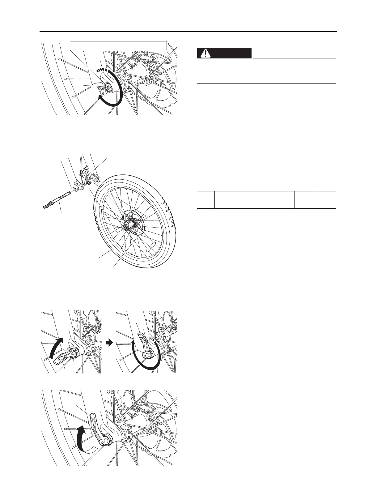
If the lever dof the front axle 2is too hard and
cannot be lowered, or if it is too loose and cannot
be lowered for it to be locked, turn the lever d
again to loosen or tighten it, adjusting so that it can
be fastened securely.
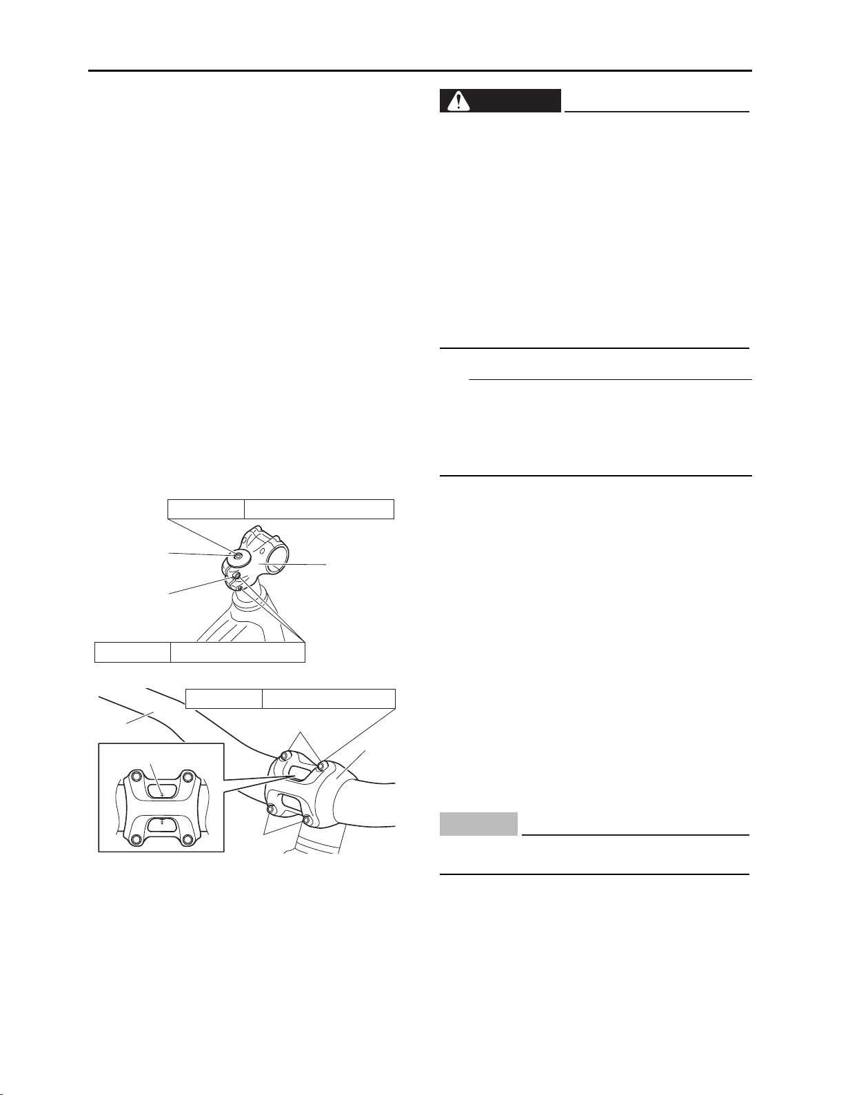
2. Installing the handlebar stem
Position the handlebar stem ain a straight line
with the front wheel.
Tighten the bolts band c, in that order, to the
specified torques.
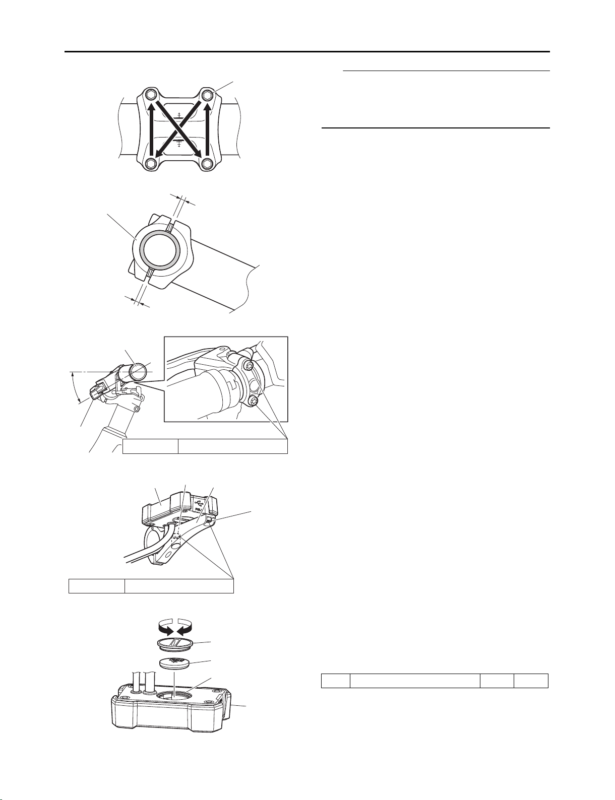
3. Installing the handlebar
Install the handlebar aso that the 3rd horizon-
tal line from the top of the alignment mark b
shown is positioned at the lower end of the hole
in the upper handlebar holder c, and then
tighten the 4 bolts dof the handlebar holder c
to the specified torque.
8Position the lever when it cannot touch
obstacles while the bicycle is moving. If not,
the lever could be unlocked unexpectedly,
causing the front wheel to come off, result-
ing in an accident with severe injury or
death.
8Fasten the lever dat position where the tip
does not touch other parts when the lever
dis lowered.
8Fasten the lever dfacing backward from
the direction of travel in such a way that it
cannot easily touch obstacles that might be
encountered while riding.
WARNING
ba
c
Tightening torque
8 N·m (0.8 kgf·m, 5.9 lb·ft)
Tightening torque
2.5 N·m (0.25 kgf·m, 1.8 lb·ft)
a
c
d
d
b
Tightening torque
6 N·m (0.6 kgf·m, 4.4 lb·ft)
The handlebar ashould not touch the frame
when it is turned fully to the left or right.
NOTICE
X1V-28107-10.book 6 ページ 2020年8月3日 月曜日 午後4時11分

INSTALLING THE INCLUDED PARTS
– 7 –
79
TIP
8Tighten bolts devenly in stages, in the order
shown in the illustration.
8Tighten in such a way that the gaps eabove
and below the handlebar holder care equal.
Install the handlebar aso that the brake lever
fis at a 30angle to the handlebar, as shown
in the illustration.
4. Installing the display unit’s button cell bat-
tery
Loosen the bolts (Torx) aand remove the dis-
play unit bfrom the bracket c.
Turn the button cell battery cover don the back
of the display unit bin direction e, remove it,
then install the button cell battery 1.
Mount the button cell battery cover d, then turn
it in direction funtil it locks.
d
ce
e
30°
a
f
Tightening torque
3.8 N·m (0.38 kgf·m, 2.8 lb·ft)
a
a
c
b
Tightening torque
2.0 N·m (0.20 kgf·m, 1.5 lb·ft)
d
ef
1
b
g1Button cell battery 1 A
X1V-28107-10.book 7 ページ 2020年8月3日 月曜日 午後4時11分

INSTALLING THE INCLUDED PARTS
– 8 –
79
After installing the button cell battery, install the
display unit onto the bracket following the
removal procedure in reverse order.
5. Installing the display unit’s
Maintain a clearance of 1 to 2 mm between the
bracket of the compact multifunction meter set
aand the handlebar holder bas shown, install
the set, and then tighten the bolt cto the spec-
ified torque.
After installing, remove the protective film.
6. Installing the front reflector
Install the front reflector 1, stay 2, and screw
3as shown, and then tighten them together to
the specified torque.
TIP
Adjust so that the front reflector 1faces straight
ahead, then tighten the screw.
7. Installing the bell
Install the bell 1in the shown, then tighten it
with the screw 2.
8Install the button cell battery with the plus
(+) mark facing upward.
8Check that the O-ring gis properly
installed.
NOTICE
a
b
c
1〜2mm
Tightening torque
3.8 N·m (0.38 kgf·m, 2.8 lb·ft)
1
2
3
Tightening torque
1.5 N·m (0.15 kgf·m, 1.1 lb·ft)
1Front reflector 1 A
2Stay 1 A
3Screw 1 A
1
2
Tightening torque
0.8 N·m (0.08 kgf·m, 0.59 lb·ft)
1Bell 1 A
2Screw 1 A
X1V-28107-10.book 8 ページ 2020年8月3日 月曜日 午後4時11分

INSTALLING THE INCLUDED PARTS
– 9 –
79
8. Routing the wires
Confirm that hoses and wires are routed in
order starting from front to back
front brake hose 1
rear brake hose 2
dropper seat wire 3
shift wire 4
compact multifunction meter lead 5
switch unit lead 6
Clamp the front brake hose 1and rear brake
hose 2with the wire clip 7at the position
shown in the illustration.
Clamp the front brake hose 1and dropper seat
wire 3with the wire clip 8at the position
shown in the illustration.
Clamp the front brake hose 1and switch unit
lead 6with the wire clip 9at the position
shown in the illustration.
Clamp the dropper seat wire 3and shift wire 4
with the wire clip 0at the position shown in the
illustration.
Clamp the dropper seat wire 3and compact
multifunction meter lead 5with the plastic lock-
ing ties qat the position shown in the illustra-
tion.
Secure the front brake hose 1with the wire
clamp wat the position shown in the illustra-
tion.
1
2
3
4
5
6
7
8
9
0
q
w
Be sure to route the wires as shown in the illus-
tration. If not, they could interfere with handle-
bar operation which could cause loss of
control.
WARNING
X1V-28107-10.book 9 ページ 2020年8月3日 月曜日 午後4時11分

INSTALLING THE INCLUDED PARTS
– 10 –
79
Make sure that the dropper seat wire 3and
compact multifunction meter lead 5are routed
as shown.
Make sure that the front brake hose 1, rear
brake hose 2, and shift wire 4are routed as
shown.
120 mm
3
5
1
2
4
X1V-28107-10.book 10 ページ 2020年8月3日 月曜日 午後4時11分

INSTALLING THE INCLUDED PARTS
– 11 –
79
Check that the rear brake hose 2, shift wire 4,
and speed sensor lead eare routed as shown
in the illustration.
9. Installing the saddle
Pinch the rail of the saddle 1with the saddle
clamps aand b, and then tighten the seat
post c, bolts d, and nuts eto the specified
torque.
TIP
Face the mark “▲” fof the saddle clamp atoward
the front, and then install the saddle.
4e
2
a
b
c
d
e
1
d
f
Tightening torque
9 N·m (0.9 kgf·m, 6.6 lb·ft)
1Saddle 1 A
X1V-28107-10.book 11 ページ 2020年8月3日 月曜日 午後4時11分

INSTALLING THE INCLUDED PARTS
– 12 –
79
10. Installing the rear reflector
Install the rear reflector 1, band 2, screw 3,
and nut 4as shown, and then tighten them
together to the specified torque.
Secure them to the frame with the band 2.
TIP
8Adjust the rear reflector 1so that it is facing
straight backward, then tighten it.
8When assembling the rear reflector 1to the
frame, adjust the length by cutting the adjust-
ment pad inside the band to fit the frame.
11. Installing the pedals
Install the pedals 1to the crank a, then tighten
to the specified torque.
TIP
8Right-hand screw (marked R) for right pedal
8Left-hand screw (marked L) for left pedal
12. Installing the battery end cap
Make sure that charging of the battery pack 1
is complete.
As shown, arrange the battery pack 1so that
the label acan be read, position the L-shaped
portion of the plate 2downward, and then
install the plate to the battery. Install the battery
end cap 3and collars 4, and then tighten the
bolts 5and screw 6to the specified torque.
12
3
4
Tightening torque
1.5 N·m (0.15 kgf·m, 1.1 lb·ft)
1
1Rear reflector 1 A
2Band 1 A
3Screw 1 A
4Nut 1 A
1
a
L R
Tightening torque
40 N·m (4.0 kgf·m, 30 lb·ft)
1Pedals (left and right) 1
each A
Tightening torque
2.0 N·m (0.20 kgf·m, 1.5 lb·ft)
1
a
2
3
6
54
1
1Battery pack 1 B
2Plate 1 A
3Battery end cap 1 A
4Collar 3 A
5Bolt 3 A
6Screw 1 A
X1V-28107-10.book 12 ページ 2020年8月3日 月曜日 午後4時11分

INSTALLING THE INCLUDED PARTS
– 13 –
79
13. Installing the battery pack
Loosen the bolts a(2 pcs), and then remove
the collars b(2 pcs) and battery cover c.
Loosen the bolts d, and then make sure that
the collar efaces downward as shown.
Insert the battery pack 1into the frame slowly
so that the protrusion fon the battery faces
toward the front of the bicycle as shown.
Insert the battery pack 1all the way into the
frame, turn the collar e180with the collar
pointing upward while holding the battery pack
1with your hand, and then insert the collar e
into the recess gin the battery.
Tighten the bolt dto the specified torque, and
then secure the battery pack 1.
TIP
Because the collar eis equipped with a magnet, it
will attach to the recess gin the battery to prevent
the collar from coming loose.
a
c
b
de
Before installing the battery, make sure that
there are neither foreign materials nor water at
the connection portion between the battery and
the bicycle, or charging connector. Otherwise,
it could lead to heat generation, smoke and/or a
fire.
WARNING
f
1
1Battery pack 1 B
e
g
d
11
d
e
Tightening torque
7 N·m (0.7 kgf·m, 5.2 lb·ft)
X1V-28107-10.book 13 ページ 2020年8月3日 月曜日 午後4時11分

INSTALLING THE INCLUDED PARTS
– 14 –
79
Hook the claw iof the battery cover to the
hook part hof the motor cover, and then install
the battery cover calong the frame.
Install the collars b(2 pcs), and then tighten
the bolts a(2 pcs) to the specified torque.
14. Adjusting the display unit’s time
TIP
Adjust the time with the button cell battery installed.
If the time is adjusted without a battery installed,
the time set will not be kept.
A. Press the power switch ato turn on the power.
B. Press and hold the function select switch b(2
seconds or longer) until the function display c
switches to the main menu display.
C. Press the “▼” assist mode switch d, display
“TIME ADJ” on the main menu display, then
press the function select switch bto set.
D. The hours value increases when the “▲” assist
mode switch fis pressed while the “Hour” sec-
tion of the clock eis flashing.
The hours value decreases when the “▼” assist
mode switch dis pressed.
Press the function select switch bto set the
hours.
a
c
hi
b
Tightening torque
2.0 N·m (0.20 kgf·m, 1.5 lb·ft)
d
ba
c
d
f
e
b
X1V-28107-10.book 14 ページ 2020年8月3日 月曜日 午後4時11分

INSTALLING THE INCLUDED PARTS
– 15 –
79
E. The minutes value increases when the “▲”
assist mode switch fis pressed while the “Min-
ute” section of the clock eis flashing.
The minutes value decreases when the “▼”
assist mode switch dis pressed.
Press the function select switch bto set the
minutes.
F. The time is set and the mode returns to the nor-
mal mode.
TIP
If you make a mistake adjusting the time, start over
from step B.
G. Press the power switch ato complete adjust-
ment of the time.
15. Checking the operation of the speed sensor
A. Press the power switch ato turn on the power.
B. Long-press the power switch a(approximately
10 seconds) within 30 seconds after turning on
the power, check that the display switches to the
diagnosis function selection screen b, then
release the power switch a.
C. Press the “▼” assist mode switch c, display
“SPEED SNSR” on the diagnosis function
selection screen b, then press the function
select switch dto set.
D. Check that the speedometer eis displayed and
that the speed sensor checking mode has been
set.
E. The number displayed on the speedometer e
counts up when the rear wheel is lifted off the
ground and turned.
The number increases by 1 for 1 turn. Check
that the position of the wheel at which the dis-
play counts up is stable.
F. After checking the operation, press the power
switch ato quit.
TIP
Turn the rear wheel at least 3 revolutions and check
that the display reads “3”.
16. Adjusting the opening of the front and rear
brake levers
Before adjusting the opening of the brake
levers, grip the brake levers approximately 10
times to pump them.
Turn the adjusting screw 1to adjust the open-
ing of the tip of the brake lever afrom the tip of
the grip.
f
a
e
d
b
a
b
c
d
a
e
a
b
c
1bdirection Opening gets larger.
cdirection Opening gets smaller.
X1V-28107-10.book 15 ページ 2020年8月3日 月曜日 午後4時11分

INSTALLING THE INCLUDED PARTS
– 16 –
79
TIP
Adjust to a position at which it is easy for the cus-
tomer to operate the front and rear brake levers and
within the range of play of the brake levers.
After adjusting the brake lever opening, check
that the rotation of the front and rear wheels is
not heavy.
NOTICE
X1V-28107-10.book 16 ページ 2020年8月3日 月曜日 午後4時11分

PREDELIVERY INSPECTION
– 17 –
79
PREDELIVERY INSPECTION
8Handlebar orientation, height, angle, and tightening
8Saddle orientation, height, angle, and tightening
* Check that the saddle is firmly fastened.
8Various fittings adjusted to the customer’s riding posture
* Including brake lever angle, fork suspension air pressure, etc.
8Inspection of the wheels, hubs, and spokes
8Tightening of the pedals
8Tightening of the screws of each part
8Brake performance
8Shift changing operation
8Looseness of the chain
8Bell sound
8Battery pack locking operation
* Check that the battery pack locks securely.
8Check of battery pack and battery charger operation
8Operation of the meter, switches, and drive unit
8Installation state of the reflectors
8Maximum tire air pressure
Front tire: 450 kPa (4.5 kgf/cm2, 65 psi)
Rear tire: 450 kPa (4.5 kgf/cm2, 65 psi)
After completing the installation, inspect the items as follows and check that there are no problems
before delivering the bicycle. Adjust controls and saddle height to the customer’s satisfaction
according to this manual.
WARNING
X1V-28107-10.book 17 ページ 2020年8月3日 月曜日 午後4時11分

X1V-28107-10.book 1 ページ 2020年8月3日 月曜日 午後4時11分
This manual suits for next models
7
Table of contents
Other Yamaha Bicycle manuals

Yamaha
Yamaha Tricity MW125A User manual

Yamaha
Yamaha AG200FZ User manual

Yamaha
Yamaha HAIBIKE SDURO HardSeven SL User manual

Yamaha
Yamaha Waverunner FX 160 User manual

Yamaha
Yamaha Urban Rush PW70URL User manual

Yamaha
Yamaha YDX-MORO 07 User manual

Yamaha
Yamaha CROSS CONNECT Series User manual

Yamaha
Yamaha X0S Series User manual

Yamaha
Yamaha Waverunner FX 160 User manual

Yamaha
Yamaha X94 Series User manual