Yamaha ICP1 User manual

SERVICE MANUAL
■ CONTENTS(目次)
SPECIFICATIONS(総合仕様)...................................................................3
PANEL LAYOUT(パネルレイアウト)........................................................4
DISASSEMBLY PROCEDURE(分解手順)..............................................5
LSI PIN DESCRIPTION(LSI端子機能表)...............................................8
IC BLOCK DIAGRAM(ICブロック図).................................................. 11
CIRCUIT BOARDS(シート基板図)....................................................... 12
TEST PROGRAM(テストプログラム).................................................. 15
UPDATING THE PROGRAM(プログラムのアップデート)............... 15
PARTS LIST
BLOCK DIAGRAM(ブロックダイアグラム)
CIRCUIT DIAGRAM(回路図)
Copyright (c)Yamaha Corporation.All rights reserved. ’04.09
PA 011743
200408-オープンプライス
INTELLIGENT CONTROL PANEL
ICP1
w
w
w
.
x
i
a
o
y
u
1
6
3
.
c
o
m
Q
Q
3
7
6
3
1
5
1
5
0
9
9
2
8
9
4
2
9
8
T
E
L
1
3
9
4
2
2
9
6
5
1
3
9
9
2
8
9
4
2
9
8
0
5
1
5
1
3
6
7
3
Q
Q
TEL 13942296513 QQ 376315150 892498299
http://www.xiaoyu163.com

ICP1
2
IMPORTANT NOTICE
This manual has been provided for the use of authorizedYamaha Retailers and their service personnel.It has been assumed
that basic service procedures inherent to the industry, and more specifically Yamaha Products, are already known and
understood by the users, and have therefore not been restated.
WARNING : Failure to follow appropriate service and safety procedures when servicing this product may result in
personal injury, destruction of expensive components and failure of the product to perform as
specified. For these reasons, we advise allYamaha product owners that all service required should
be performed by an authorizedYamaha Retailer or the appointed service representative.
IMPORTANT : This presentation or sale of this manual to any individual or firm does not constitute authorization,
certification, recognition of any applicable technical capabilities, or establish a principal-agent
relationship of any form.
The data provided is believed to be accurate and applicable to the unit (s) indicated on the cover.The research engineering,
and service departments of Yamaha are continually striving to improveYamaha products. Modifications are, therefore,
inevitable and changes in specification are subject to change without notice or obligation to retrofit.Should any discrepancy
appear to exist, please contact the distributor’s Service Division.
WARNING : Static discharges can destroy expensive components. Discharge any static electricity your body
may have accumulated by grounding yourself to the ground bus in the unit (heavy gauge black wires
connect to this bus).
IMPORTANT : Turn the unit OFF during disassembly and parts replacement. Recheck all work before you apply
power to the unit.
WARNING : CHEMICAL CONTENT NOTICE !
The solder used in the production of this product contains LEAD. In addition, other electrical/electronic and/or plastic
(where applicable) components may also contain traces of chemicals found by the California Health and Welfare Agency
(and possibly other entities) to cause cancer and/or birth defects or other reproductive harm.
DO NOT PLACE SOLDER, ELECTRICAL/ELECTRONIC OR PLASTIC COMPONENTS INYOUR MOUTH FOR ANY
REASON WHAT SO EVER!
Avoid prolonged, unprotected contact between solder and your skin!When soldering, do not inhale solder fumes or expose
eyes to solder/flux vapor!
If you come in contact with solder or components located inside the enclosure of this product, wash your hands before
handling food.
■WARNING
Components having special characteristics are marked Zand must be replaced with parts having specification equal to
those originally installed.
IMPORTANT NOTICE FORTHE UNITED KINGDOM
Connecting the Plug and Cord
IMPORTANT.The wires in this mains lead are coloured in accordance with the following code:
BLUE : NEUTRAL
BROWN : LIVE
As the colours of the wires in the mains lead of this apparatus may not correspond with the coloured makings identifying the
terminals in your plug proceed as follows:
The wire which is coloured BLUE must be connected to the terminal which is marked with the letter N or coloured BLACK.
The wire which is coloured BROWN must be connected to the terminal which is marked with the letter L or coloured RED.
Making sure that neither core is connected to the earth terminal of the three pin plug.
• This applies only to products distributed byYamaha-Kemble Music (U.K.) Ltd.
Z印の部品は、安全を維持するために重要な部品です。交換する場合は、安全のために必ず指定の部品をご使用ください。
w
w
w
.
x
i
a
o
y
u
1
6
3
.
c
o
m
Q
Q
3
7
6
3
1
5
1
5
0
9
9
2
8
9
4
2
9
8
T
E
L
1
3
9
4
2
2
9
6
5
1
3
9
9
2
8
9
4
2
9
8
0
5
1
5
1
3
6
7
3
Q
Q
TEL 13942296513 QQ 376315150 892498299
http://www.xiaoyu163.com
ICP1
3
■SPECIFICATIONS(総合仕様)
ICP1 adaptor boxControl panel unit
120
162
101
92 45.40
37.30
105
60
26.40
110
Frame plate for ICP1
83.50
101
132
75.50
142
92
115
65 30
AC adaptor (PA-300)
(Unit: mm)
(コントロールパネル本体)
(フレームプレート)
(アダプターボックス)
(AC アダプターPA-300
)
EthernetTerminals
(100Base-TX/10Base-T Ethernet, RJ-45)
Pin Connection
1 TxD+
2 TxD-
3 RxD+
4 Unused
5 Unused
6 RxD-
7 Unused
8 Unused
Pin Connection
1 TxD+
2 TxD-
3 RxD+
4 +16V
5 +16V
6 RxD-
7 GND
8 GND
Straight/Cross Cable Wiring Details
Straight Cables Cross Cables
Pins
1 –– 1
2 –– 2
3 –– 3
4 –– 4
5 –– 5
6 –– 6
7 –– 7
8 –– 8
Pins
1 –– 3
2 –– 6
3 –– 1
4 –– 4
5 –– 5
6 –– 2
7 –– 7
8 –– 8
All pins are used on the straight cable connecting
the control panel unit and adaptor box.
Adaptor box to network Control panel
to adaptor box connection Terminal Format Connector
Ethernet 100Base-TX/10Base-TX RJ45
Conditions Range
Operating temperature range
10 –35˚C
Storage temperature range
-20 –60˚C
Control I/O Characteristics
Temperature range
Net Weight: 1kg
本体とアダプターボックス間のストレートケーブルは、
すべてのピンを使用します。
w
w
w
.
x
i
a
o
y
u
1
6
3
.
c
o
m
Q
Q
3
7
6
3
1
5
1
5
0
9
9
2
8
9
4
2
9
8
T
E
L
1
3
9
4
2
2
9
6
5
1
3
9
9
2
8
9
4
2
9
8
0
5
1
5
1
3
6
7
3
Q
Q
TEL 13942296513 QQ 376315150 892498299
http://www.xiaoyu163.com
ICP1
4
■PANEL LAYOUT(パネルレイアウト)
qw ui
o!0
!2!1
rty
e
q[F1] Button
w[F2] Button
e[F3] Button
r[F4/UTILITY] Button
t[F5] Button
y[F6/MUTE] Button
u[HOME] Button
i[SCENE] Button
o[CANCEL] Button
!0 [ENTER] Button
!1 Display
!2 Dial
q[F1]ボタン
w[F2]ボタン
e[F3]ボタン
r[F4/UTILITY]ボタン
t[F5]ボタン
y[F6/MUTE]ボタン
u[HOME]ボタン
i[SCENE]ボタン
o[CANCEL]ボタン
!0[ENTER]ボタン
!1ディスプレイ
!2ダイアル
w
w
w
.
x
i
a
o
y
u
1
6
3
.
c
o
m
Q
Q
3
7
6
3
1
5
1
5
0
9
9
2
8
9
4
2
9
8
T
E
L
1
3
9
4
2
2
9
6
5
1
3
9
9
2
8
9
4
2
9
8
0
5
1
5
1
3
6
7
3
Q
Q
TEL 13942296513 QQ 376315150 892498299
http://www.xiaoyu163.com
ICP1
5
■DISASSEMBLY PROCEDURE(分解手順)
Dust proof case
(防塵ケース)
Contact
(接触子)
LCD
(液晶ディスプレイ)
Encoder knob
(エンコーダツマミ)
[40]
[90]
[40]
[120]
[140]
[140]
PN
LCD1
DM
LCD2
Install these 2 screws first when
installing the dust proof case.
(防塵ケースを取り付ける際は、
この2 本のネジを先に止めます。)
Contact
(接触子)
1
Direct the side with overlapping claws
to the RJ45 connector port.
(爪の重なっている方をRJ45コネクタ
挿入口にむけます。)
Match to the center of RJ45
connector for horizontal alignment.
(横方向はRJ45コネクタの中心に
合わせます。)
●Detailed figure showing the contact attaching position
(接触子貼付位置詳細)
注意事項
1. フィラメントテープは、取り外す前と同じように取り
付けてください。
2. フラットケーブルの表・裏を逆に差し込まないように
注意して取り付けてください。(写真1)
Caution:
1. Be sure to attach the removed filament tape just
as it was before removal.
2. Pay attention not to insert and install the cable to
the connector inversely. (Photo 1)
Front Side (Printed Side)
表面(印刷面) Back Side
裏面
Photo 1(写真1)
Fig. 1(図1)
[40]: Spacer (六角スペーサ)
M3.0 (V7332700)
[90]: BindHeadTappingScrew-B (+バインドBタイト)
2.6X8MFZN2BL (VB096700)
[120]: FlatHeadTappingScrew-S (Sタイト平頭)
3.0X6MFZN2BL (WD010800)
[140]: FlatHeadTappingScrew-S (Sタイト平頭)
3.0X6MFZN2BL (WD010800)
1. Dust Proof Case
(Time required: About 1 minute)
1-1 Remove the four (4) screws marked [140]. The dust
proof case can then be removed. (Fig. 1)
1. 防塵ケース(所要時間:約1分)
1-1 [140]のネジ4本を外し、防塵ケースを外します。
(図1)
w
w
w
.
x
i
a
o
y
u
1
6
3
.
c
o
m
Q
Q
3
7
6
3
1
5
1
5
0
9
9
2
8
9
4
2
9
8
T
E
L
1
3
9
4
2
2
9
6
5
1
3
9
9
2
8
9
4
2
9
8
0
5
1
5
1
3
6
7
3
Q
Q
TEL 13942296513 QQ 376315150 892498299
http://www.xiaoyu163.com
ICP1
6
2. DM Circuit Board
(Time required: About 2 minutes)
2-1 Remove the dust proof case. (See procedure 1)
2-2 Remove the two (2) screws marked [120].The encoder
knob and DM circuit board can then be removed.
(Fig. 1)
* Remove the contact from the DM circuit board. (Fig.1)
3. LCD (Time required: About 2 minutes)
3-1 Remove the dust proof case. (See procedure 1)
3-2 Remove the DM circuit board. (See procedure 2)
3-3 Remove the four (4) screws marked [90]. The LCD,
LCD1 circuit board and LCD2 circuit board can then
be removed. (Fig. 1)
* To remove the cable, release the retainer of the
connector in the direction of the arrow shown in the
photo and pull out the connector. (Photo 2)
4. PN circuit board
(Time required: About 3 minutes)
4-1 Remove the dust proof case. (See procedure 1)
4-2 Remove the DM circuit board. (See procedure 2)
4-3 Remove the LCD. (See procedure 3)
4-4 Remove the four (4) spacers marked [40]. The PN
circuit board can then be removed. (Fig. 1)
2. DMシート(所要時間:約2分)
2-1 防塵ケースを外します。(1項参照)
2-2 [120]のネジ2本を外し、エンコーダツマミとDMシー
トを外します。(図1)
※ DMシートより、接触子を外します。(図1)
3. 液晶ディスプレイ(所要時間:約2分)
3-1 防塵ケースを外します。(1項参照)
3-2 DMシートを外します。(2項参照)
3-3 [90]のネジ4本を外し、液晶ディスプレイとLCD1
シートとLCD2シートを外します。(図1)
※ ケーブルを外す際、矢印の方向にコネクタのツメを解除し
てから抜いてください。(写真2)
4. PNシート(所要時間:約3分)
4-1 防塵ケースを外します。(1項参照)
4-2 DMシートを外します。(2項参照)
4-3 液晶ディスプレイを外します。(3項参照)
4-4 [40]の六角スペーサ4本を外し、PNシートを外しま
す。(図1)
Photo 2(写真2)
LCD
(液晶ディスプレイ)
w
w
w
.
x
i
a
o
y
u
1
6
3
.
c
o
m
Q
Q
3
7
6
3
1
5
1
5
0
9
9
2
8
9
4
2
9
8
T
E
L
1
3
9
4
2
2
9
6
5
1
3
9
9
2
8
9
4
2
9
8
0
5
1
5
1
3
6
7
3
Q
Q
TEL 13942296513 QQ 376315150 892498299
http://www.xiaoyu163.com
ICP1
7
1. Lower Case
(Time required: About 1 minute)
1-1 Remove the three (3) screws marked [50]. The lower
case can then be removed. (Fig. 1)
2. PW Circuit Board
(Time required: About 1 minute)
2-1 Remove the lower case. (See procedure 1)
2-2 Remove the two (2) screws marked [30]. The PW
circuit board can then be removed. (Fig. 1, 2)
1. 下ケース(所要時間:約1分)
1-1 [50]のネジ3本を外し、下ケースを外します。(図1)
2. PWシート(所要時間:約1分)
2-1 下ケースを外します。(1項参照)
2-2 [30]のネジ2本を外し、PWシートを持ち上げて外し
ます。(図1、2)
●PW BOX
Lower case
(下ケース)[30]
[50]
PW
Lower case
(下ケース)
PW
[30]: BindHeadTappingScrew-B (+バインドBタイト) 3.0X6MFZN2BL (EP600230)
[50]: FlatHeadTappingScrew-B (+皿Bタイト) 3.0X8MFZN2BL (EP600790)
Fig. 1(図1)
Fig. 2(図2)
w
w
w
.
x
i
a
o
y
u
1
6
3
.
c
o
m
Q
Q
3
7
6
3
1
5
1
5
0
9
9
2
8
9
4
2
9
8
T
E
L
1
3
9
4
2
2
9
6
5
1
3
9
9
2
8
9
4
2
9
8
0
5
1
5
1
3
6
7
3
Q
Q
TEL 13942296513 QQ 376315150 892498299
http://www.xiaoyu163.com

8
ICP1
■LSI PIN DESCRIPTION
HD6417727F160C (X2890B00) CPU . . . . . . . . . . . . . . . . . . . . . . . . . . . . . . . . . . . . . . . . . . . . . . . . . . 9
ICS1893 (XZ658A00) PHY (Physical Layer) . . . . . . . . . . . . . . . . . . . . . . . . . . . . . . . . . . . . . . . . . . . . . 8
SIS60000F00A500 (X4834A00) Intelligent Network Controller . . . . . . . . . . . . . . . . . . . . . . . . . . . 10
PIN
NO. I/O FUNCTIONNAME PIN
NO. I/O FUNCTIONNAME
1
2
3
4
5
6
7
8
9
10
11
12
13
14
15
16
17
18
19
20
21
22
23
24
25
26
27
28
29
30
31
32
NOD/REP
10/100SEL
TP_CT
VSS
TP_TXP
TP_TXN
VDD
VDD
10TCSR
100TCSR
VSS
VSS
TP_RXP
TP_RXN
VDD
VDD
VSS
RESETn
MII/SI
NC
LSTA
VSS
HW/SW
DPXSEL
VDD
ANSEL
LOCK
VSS
VSS
MDIO
MDC
RXD3
I
I/O
O
O
I
I
I
I
I
I
O
I
I/O
I/O
O
I/O
I
O
Node / Repeater (Select).
10Base-T / 100Base-TX Select.
Ground
Twisted-Pair Transmit (Data) Positive.
Twisted-Pair Transmit (Data) Negative.
Power
Power
10M Transmit Current Set Resistor.
100M Transmit Current Set Resistor.
Ground
Ground
Twisted-Pair Receive (Data) Positive.
Twisted-Pair Receive (Data) Negative.
Power
Power
Ground
(System) Reset (Active Low).
Media Independent Interface / Stream Interface (Select).
N.C.
Link Status.
Ground
Hardware / Sofrtware (Select).
Half-Duplex / Full-Duplex Select.
Power
Auto-Negotiation Select.
(Stream Cipher) Lock (Acquired).
Ground
Ground
Management Data Input / Output.
Management Data Clock.
Receive Data 3.
33
34
35
36
37
38
39
40
41
42
43
44
45
46
47
48
49
50
51
52
53
54
55
56
57
58
59
60
61
62
63
64
RXD2
RXD1
RXD0
RXDV
VDD_IO
RXCLK
RXER
VSS
RXTRI
TXER
TXCLK
TXEN
TXD0
TXD1
TXD2
TXD3
COL
CRS
VDD_IO
REF_OUT
REF_IN
VDD
P0AC
VSS
VSS
VSS
P1CL
P2LI
VSS
P3TD
VDD
P4RD
O
O
O
O
O
O
I
I
O
I
I
I
I
I
O
O
I
I
I/O
I/O
I/O
I/O
I/O
Receive Data 2.
Receive Data 1.
Receive Data 0.
Receive Data Valid.
Power
Receive Clock.
Receive Error.
Ground
Receive (Interface), Tri-State.
Transmit Error.
Transmit Clock.
Transmit Enable.
Transmit Data 0.
Transmit Data 1.
Transmit Data 2.
Transmit Data 3.
Collision (Detect).
Carrier Sense.
Power
(Frequency) Reference Output.
(Frequency) Reference Input.
Power
PHY (Address Bit) 0 / Activity LED.
Ground
Ground
Ground
PHY (Address Bit) 1 / Collision LED.
PHY (Address Bit) 2 / Link Integrity LED.
Ground
PHY (Address Bit) 3 / Transmit Data LED.
Power
PHY (Address Bit) 4 / Receive Data LED.
ICS1893 (XZ658A00) PHY (Physical Layer)
DM: IC406
(LSI端子機能表)
w
w
w
.
x
i
a
o
y
u
1
6
3
.
c
o
m
Q
Q
3
7
6
3
1
5
1
5
0
9
9
2
8
9
4
2
9
8
T
E
L
1
3
9
4
2
2
9
6
5
1
3
9
9
2
8
9
4
2
9
8
0
5
1
5
1
3
6
7
3
Q
Q
TEL 13942296513 QQ 376315150 892498299
http://www.xiaoyu163.com
9
ICP1
PIN
NO.
1
2
3
4
5
6
7
8
9
10
11
12
13
14
15
16
17
18
19
20
21
22
23
24
25
26
27
28
29
30
31
32
33
34
35
36
37
38
39
40
41
42
43
44
45
46
47
48
49
50
51
52
53
54
55
56
57
58
59
60
61
62
63
64
65
66
67
68
69
70
71
72
73
74
75
76
77
78
79
80
81
82
83
84
85
86
87
88
89
90
91
92
93
94
95
96
97
98
99
100
101
102
103
104
105
106
107
108
109
110
111
112
113
114
115
116
117
118
119
120
Vcc-RTC
XTAL2
EXTAL2
Vss-RTC
MD1
MD2
NMI
IRQ0/IRL0_/PTH[0]
IRQ1/IRL1_/PTH[1]
IRQ2/IRL2_/PTH[2]
IRQ3/IRL3_/PTH[3]
IRQ4/PTH[4]
VEPWC
VCPWC
MD5
/BREQ
/BACK
VssQ
CKIO2
VccQ
D31/PTB[7]
D30/PTB[6]
D29/PTB[5]
D28/PTB[4]
D27/PTB[3]
D26/PTB[2]
D25/PTB[1]
D24/PTB[0]
VssQ
D23/PTA[7]
VccQ
D22/PTA[6]
D21/PTA[5]
D20/PTA[4]
Vss
D19/PTA[3]
Vcc
D18/PTA[2]
D17/PTA[1]
D16/PTA[0]
D15
VssQ
D14
VccQ
D13
D12
D11
D10
D9
D8
D7
D6
VssQ
D5
VccQ
D4
D3
D2
D1
D0
A0
A1
A2
VssQ
A3
VccQ
A4
A5
A6
A7
A8
A9
A10
A11
VssQ
A12
VccQ
A13
A14
A15
A16
A17
A18
A19
A20
VssQ
A21
VccQ
A22
A23
Vss
A24
Vcc
A25
BS_/PTK[4]
RD_
WE0_/DQMLL
WE1_/DQMLU/WE
WE2_/DQMUL/ICIORD_/PTK[6]
VssQ
WE3_/DQMUU/ICIOWR_/PTK{7}
VccQ
RD/WR_
PTE[7]/PCC0RDY/AUDSYNC_
/CS0
/CS2
/CS3
/CS4/PTK[2]
/CS5/CE1A_/PTK[3}
/CS6/CE1B_
CE2A_/PTE[4]
CE2B_/PTE[5]
AFE_HC1/USB1d_DPLS/PTK[0]
AFE_RLYCNT_/USB1d_DMNS/PTK[1]
VssQ
AFE_SCLK/USB1d_TXDPLS
VccQ
PTM[7]/PTINT[7]/AFE_FS/USB1d_RCV
PTM[6]/PTINT[6]/AFE_RXIN/USB1d_SPEED
PTM[5]/PTINT[5]/AFE_TXOUT/USB1d_TXSE0
-
-
-
-
-
-
-
I
I
I
I
I
O
-
-
-
-
-
-
-
I/O
I/O
I/O
I/O
I/O
I/O
I/O
I/O
-
I/O
-
I/O
I/O
I/O
-
I/O
-
I/O
I/O
I/O
-
-
-
-
-
-
-
-
-
-
-
-
-
-
-
-
-
-
-
-
-
-
-
-
-
-
-
-
-
-
-
-
-
-
-
-
-
-
-
-
-
-
-
-
-
-
-
-
-
-
-
-
-
-
O
-
O
O
O
-
O
-
O
O
-
-
-
O
O
O
O
O
O
O
-
I
-
I
I
I
Power supply for RTC (1.9V)
Not in use (XTAL for internal RTC)
Power supply for RTC (0V)
Clock mode setting
Not in use (Non-maskable interrupt request)
External interrupt request
VEE control pin for LCD panel
VCC control pin for LCD panel
Big endian setting
Not in use (bus request)
Bus acknowledge
VssQ
System clock output
VccQ
Data bus
VssQ
Data bus
VccQ
Data bus
Vss
Data bus
Vcc
Data bus
VssQ
Data bus
VccQ
Data bus
VssQ
Data bus
VccQ
Data bus
Address bus
VssQ
Address bus
VccQ
Address bus
VssQ
Address bus
VccQ
Address bus
VssQ
Address bus
VccQ
Address bus
Vss
Address bus
Vcc
Address bus
Not connected (bus cycle start signal)
Read strobe
Write 0 signal
Write 1 signal
Write 2 signal
VssQ
Write 3 signal
VccQ
Read/Write
I/O
Chip Select 0
Chip Select 2
Chip Select 3
Chip Select 4
Chip Select 5
Chip Select 6
Output port (SWP50 Reset)
Output port (PLG Board Reset)
SPD DATA
SPD CL
VssQ
Not in use (USB1 D+ transmission)
VccQ
Not in use
PIN
NO.
121
122
123
124
125
126
127
128
129
130
131
132
133
134
135
136
137
138
139
140
141
142
143
144
145
146
147
148
149
150
151
152
153
154
155
156
157
158
159
160
161
162
163
164
165
166
167
168
169
170
171
172
173
174
175
176
177
178
179
180
181
182
183
184
185
186
187
188
189
190
191
192
193
194
195
196
197
198
199
200
201
202
203
204
205
206
207
208
209
210
211
212
213
214
215
216
217
218
219
220
221
222
223
224
225
226
227
228
229
230
231
232
233
234
235
236
237
238
239
240
PTM[4]/PINT[4]/AFE_RDET_/USB1d_TXDMNS
Reserved/USB1d_SUSPEND
USB1_ovr_crnt/USBF_VBUS
USB2_ovr_crnt_
RTS2_/USB1d_TXENL
PTE[2]/USB1_pwr_en
PTE[1]/USB2_pwr_en
CKE/PTK[5]
/RAS3/PTJ[0]
Reserved/PTJ[1]
Reserved//CAS/PTJ[2]
VssQ
Reserved/PTJ[3]
VccQ
Reserved/PTJ[4]
Reserved/PTJ[5]
Vss
PTD[5]/CL1
Vcc
PTD[7]/DON
PTE[6]/M_DISP
PTE[3]/FLM
PTE[0]/TDO
PCC0RESET/DRACK0
PCC0DRV_/DACK0_
/WAIT
/RESETM
/ADTRG/PTH[5]
/IOIS16/PTG[7]
/ASEMD0
PTG[5]/ASEBRKAK_
PTG[4]
PCC0BVD2/PTG[3]/AUDATA[3]
PCC0BVD1/PTG[2]/AUDATA[2]
Vss
PCC0CD2/PTG[1]/AUDATA[1]
Vcc
PCC0CD1/PTG[0]/AUDATA[0]
VssQ
PTF[7]/PINT[15]/TRST_
VccQ
PTF[6]/PINT[14]/TMS
PTF[5]/PINT[13]/TDI
PTF[4]/PINT[12]/TCK
PTF[3]/PINT[11]/Reserved
PCCREG_/PTF[2]/Reserved
PCC0VS1_/PTF[1]/Reserved
PCC0VS2_/PTF[0]/Reserved
MD0
Vcc-PLL1
CAP1
Vss-PLL1
Vss-PLL2
CAP2
Vcc-PLL2
PCC0WAIT_/PTH[6]/AUDCK
Vss
Vcc
XTAL
EXTAL
LCD15/PTM[3]/PINT[10]
LCD14/PTM[2]/PINT[9]
LCD13/PTM[1]/PINT[8]
LCD12/PTM[0]
STATUS0/PTJ[6]
STATUS1/PTJ[7]
CL2/PTH[7]
VssQ
CKIO
VccQ
TxD0/SCPT[0]
SCK0/SCPT[1]
TxD_SIO/SCPT[2]
SIOMCLK/SCPT[3]
TxD2/SCPT[4]
SCK_SIO/SCPT[5]
SIOFSYNC/SCPT[6]
RxD0/SCPT[0]
RxD_SIO/SCPT[2]
Vss
RxD2/SCPT[4]
Vcc
SCPT[7]/CTS2_/IRQ5
LCD11/PTC[7]/PINT[3]
LCD10/PTC[6]/PINT[2]
LCD9/PTC[5]/PINT[1]
VssQ
LCD8/PTC[4]/PINT[0]
VccQ
LCD7/PTD[3]
LCD6/PTD[2]
LCD5/PTC[3]
LCD4/PTC[2]
LCD3/PTC[1]
LCD2/PTC[0]
LCD1/PTD[1]
LCD0/PTD[0]
DREQ0_/PTD[4]
LCK/UCLK/PTD[6]
/RESETP
CA
MD3
MD4
/Scan_testen
Avcc_USB
USB1_P
USB1_M
Avss_USB
USB2_P
USB2_M
Avcc_USB
Avss
AN[2]/PTL[2]
AN[3]/PTL[3]
AN[4]/PTL[4]
AN[5]/PTL[5]
Avcc
AN[6]/PTL[6]/DA[1]
AN[7]/PTL[7]/DA[0]
Avss
I
O
I
-
O
O
O
O
O
O
O
-
O
-
O
O
-
O
-
O
O
O
O
O
O
-
-
I
I
-
I
I
I
-
I
-
I
-
I
-
I
I
I
I
I
I
I
-
-
-
-
-
-
-
I
-
-
-
-
I
I
I
I
O
O
O
-
-
-
O
O
O
O
O
O
O
i
i
-
i
-
I
O
O
O
-
O
-
O
O
O
O
O
O
O
O
I
I
-
-
-
-
-
-
IO
IO
-
IO
IO
-
-
I
I
I
I
-
I
O
-
Not in use
USB function VBUS
USB2_HOST2 over current detection
Not in use
USB1 voltage control
USB2 voltage control
Enable (SDRAM)
RAS for SDRAM
Not in use
CAS for SDRAM
VssQ
Output port (DAC Reset)
VccQ
Output port (SIO Reset)
Output port (DAC Mute)
Vss
LCD line clock
Vcc
LCD DISPLAY ON
LCD alternater
LCD frame line marker
JTAG (test data output)
DMA request acceptance
DMA acknowledge
Hardware wait request
Manual reset request
Analog A/D trigger
Not in use
Vss
Not in use
Vcc
Not in use
VssQ
Not in use
VccQ
Not in use
Clock mode setting
Power supply for Vcc_PLL1 - PLL1(1.9V)
External capacitance for CAP1 _ PLL1
Power supply for Vss_PLL1 _ PLL1(0V)
Power supply for Vss_PLL2 _ PLL2 (0V)
External capacitance for CAP2 _ PLL2
Power supply for Vcc_PLL2 _ PLL2 (1.9V)
Not in use
Vss
Vcc
Clock oscillator
External clock
Not in use
Input port (Flash ROM RY/BY)
Output port (Flash ROM write protect)
Output port (Flash ROM ACC)
LCD clock output
VssQ
System clock input/output (for SDRAM)
VccQ
Output port for SCI
Not in use
Output port for SCI
Not in use
Receiving data 0
Not in use
Vss
Receiving data 2
Vcc
Not in use
Output port (PLG CLOCK ON/OFF)
Not in use
VssQ
Not in use
VccQ
LCD DATA7
LCD DATA6
LCD DATA5
LCD DATA4
LCD DATA3
LCD DATA2
LCD DATA1
LCD DATA0
DMA request
USB clock
Power on reset request
Hardware standby request
Bus width setting for area0
Test pin (fixed to 3.3V)
USB analog power supply (3.3V)
USB1 data input/output (+)
USB1 data input/output (-)
USB analog power supply (0V)
USB2 data input/output (+)
USB2 data input/output (-)
USB analog power supply (3.3V)
A/D analog power supply (0V)
AD converter input
A/D analog power supply (3.3V)
AD converter input
DA converter output (LCD contrast)
A/D analog power supply (0V)
I/O I/O
NAME FUNCTION FUNCTION
NAME
HD6417727F160C (X2890B00) CPU
DM2-EL: IC006
DM: IC104
w
w
w
.
x
i
a
o
y
u
1
6
3
.
c
o
m
Q
Q
3
7
6
3
1
5
1
5
0
9
9
2
8
9
4
2
9
8
T
E
L
1
3
9
4
2
2
9
6
5
1
3
9
9
2
8
9
4
2
9
8
0
5
1
5
1
3
6
7
3
Q
Q
TEL 13942296513 QQ 376315150 892498299
http://www.xiaoyu163.com

10
ICP1
PIN
NO. I/O FUNCTION
NAME PIN
NO. I/O FUNCTION
NAME
1
2
3
4
5
6
7
8
9
10
11
12
13
14
15
16
17
18
19
20
21
22
23
24
25
26
27
28
29
30
31
32
33
34
35
36
37
38
39
40
41
42
43
44
45
46
47
48
49
50
GPIO15/DTR#
GPIO14/RTS#
GPIO13/DSR#
GPIO12/CTS#
GPIO11/RSV1
GPIO10/MODE
GPIO9/TXD
GPIO8/RXD
VSS
GPIO7/OSCCTL
GPIO6
GPIO5
GPIO4
GPIO3
GPIO2/CRS
GPIO1
GPIO0/INT0
VDD
EP_CS
EP_SK
EP_DI
EP_DO
SCL
SDA
VSS
MII_COL
MII_TXD3
MII_TXD2
MII_TXD1
MII_TXD0
MII_TXEN
VDD
MII_TXCLK
MII_RXER
MII_RXCLK
MII_RXDV
MII_RXD0
MII_RXD1
MII_RXD2
MII_RXD3
MDC
MDIO
OSC2
VDD
VSS
OSC1
VDD
HCS#
HA0
HA1
I/O
I/O
I/O
I/O
I/O
I/O
I/O
I/O
I/O
I/O
I/O
I/O
I/O
I
I/O
I/O
O
O
I
O
OD/I
OD/I
I
O
O
O
O
O
I
I
I
I
I
I
I
I
O
I/O
O
I
I
I
I
General Purpose I/O [15:8]
Power supply (–) GND
General Purpose I/O [7:0]
MII Carrier Sense
General Purpose I/O [7:0]
Built-in logic power supply (+)
EEPROM Chip Select
EEPROM Serial Clock
EEPROM Data In
EEPROM Data Out
I2C Serial Clock
I2C Serial Data
Power supply (–) GND
MII Collision Detect
MII Transmit Data
MII Transmit Enable
Built-in logic power supply (+)
MII Transmit Clock
MII Receive Error
MII Receive Clock
MII Receive Data Valid
MII Receive Data
MII Management Interface Clock
MII Management Interface Data I/O
OSC1 clock pin
Built-in logic power supply (+)
Power supply (–) GND
OSC1 clock pin
Built-in logic power supply (+)
Host Chip Select: It is the host interface access control signal.
Host Address: It is the host interface port select signal.
51
52
53
54
55
56
57
58
59
60
61
62
63
64
65
66
67
68
69
70
71
72
73
74
75
76
77
78
79
80
81
82
83
84
85
86
87
88
89
90
91
92
93
94
95
96
97
98
99
100
HA2
VSS
HD0
HD1
HD2
HD3
HD4
HD5
HD6
HD7
VDD
HD8
HD9
HD10
HD11
HD12
HD13
HD14
HD15
VSS
HRD0#
HRD1#
HWR0#
HWR1#
HINT
Reserve
Reserve
HIFSEL0
VDD
PLLC
TEST0
HIFSEL1
HIFSEL2
HMUX
HINTPOL
TEST1
OSC4
VSS
OSC3
VDD
RESET#
HENDIAN
HSIZE
OSCO
DSIO
DST0
DST1
DST2
DPCO
DCLK
I
I/O
I/O
I/O
I/O
I/O
I/O
I/O
I/O
I/O
I/O
I/O
I/O
I/O
I/O
I/O
I/O
I
I
I
I
Tri
I
I
I
I
I
I
I
O
I
I
I
I
O
I/O
O
O
O
O
O
Host Address: It is the host interface port select signal.
Power supply (–) GND
Host Data: Data signal line of the host interface.
Built-in logic power supply (+)
Host Data: Data signal line of the host interface.
Power supply (–) GND
Host Read/Host Write
Host Interrupt
These pins are reserved for future expansion.
Host Interface Select
Built-in logic power supply (+)
PLL capacitor connecting pin
Test Input
Host Interface Select
Host Bus Multiplex
Host Interrupt Polarity Select
Test Input
OSC3 clock pin
Power supply (–) GND
OSC3 clock pin
Built-in logic power supply (+)
Hardware Reset Input
Host Interface Endian Select
Host Bus Size Select
OSC output pin
These pins are used for communication
with the debug tool ICD33.
SIS60000F00A500 (X4834A00) Intelligent Network Controller
DM: IC402
w
w
w
.
x
i
a
o
y
u
1
6
3
.
c
o
m
Q
Q
3
7
6
3
1
5
1
5
0
9
9
2
8
9
4
2
9
8
T
E
L
1
3
9
4
2
2
9
6
5
1
3
9
9
2
8
9
4
2
9
8
0
5
1
5
1
3
6
7
3
Q
Q
TEL 13942296513 QQ 376315150 892498299
http://www.xiaoyu163.com

11
ICP1
■IC BLOCK DIAGRAM(IC ブロック図)
TC74VHC08FT (XV891A00)
Quad 2 Input AND
DM: IC102
TC74VHC74FT (XV892A00)
Dual D-Type Flip-Flop
DM: IC302
1
2
3
1A
1Y
4
2A
5
2B
6
2Y
7
VSS
1B
14
13
12
VDD
4A
11
4Y
10
3B
9
3A
8
3Y
4B
INPUTS OUTPUTS
PR CLR CLK D Q Q
L
H
H
L
H
Q
O
H
L
H
H
L
Q
O
X
X
X
H
L
X
X
X
X
f
f
L
H
L
L
H
H
H
L
H
L
H
H
H
1
2
3
4
5
6
7
1CLR
1D
1CK
1PR
1Q
1Q
GND
14
13
12
11
10
9
8
VCC
2CLR
CLR
2D
D
2CK
CK
2PR
PR
2Q
2Q
Q
Q
CLR
D
CK
PR
Q
Q
TC74VHC14FT
(XV890A00)
Hex Inverter
DM: IC304
1
2
3
4
5
6
7
1A
1Y
2A
2Y
3A
3Y
GND
14
13
12
11
10
9
8
VDD
6A
6Y
5A
5Y
4A
4Y
TC74VHC138FT (XZ495A00)
3 to 8 Demultiplexer
DM: IC401
1
2
3
4
5
6
7
A
A
Select
Enable
Output
Output
B
B
C
C
G2A
G2A
G2B
G2B
G1
G1
Y7
Y7 Y5
Y4
Y3
Y2
Y1
Y0
Y6
16
15
14
13
12
11
10
Vcc
YO
Y1
Y2
Y3
Y4
Y5
8
GND
9
Y6
TC7WH04FU (XY363A00)
Triple Inverter
DM: IC101
1
2
3
4
8
7
6
5
1A
GND
3Y
2A
Vcc
2Y
1Y
3A
NJM4558M-DTE2 (XV130A00)
Dual Operational Amplifier
DM: IC301
1
2
3
4-V
8
7
6
5
Output A
+V
Non-Inverting
Input A
-DC Voltage Supply
+DC Voltage
Supply
Output B
Inverting
Input B
Non-Inverting
Input B
Inverting
Input A
+-
+-
3
Capacitor 6Power supply
5Input
Ground 4
2
1
Switch-Collector
Switch-Emitter
S
R
Q
+
Driver
8
7Peak current detect
Generator
Comparator
1.17V
reference
voltage
M5291FP-600C (XR858A00)
DC-DC Converter
DM: IC303
w
w
w
.
x
i
a
o
y
u
1
6
3
.
c
o
m
Q
Q
3
7
6
3
1
5
1
5
0
9
9
2
8
9
4
2
9
8
T
E
L
1
3
9
4
2
2
9
6
5
1
3
9
9
2
8
9
4
2
9
8
0
5
1
5
1
3
6
7
3
Q
Q
TEL 13942296513 QQ 376315150 892498299
http://www.xiaoyu163.com

12
ICP1
■CIRCUIT BOARDS
DM (X5068B0) . . . . . . . . . . . . . . . . . . . . . . .12/13
LCD1 (X5069C0) . . . . . . . . . . . . . . . . . . . . . . . 14
LCD2 (X5069C0) . . . . . . . . . . . . . . . . . . . . . . . 14
PN (X5069C0) . . . . . . . . . . . . . . . . . . . . . . . . . . 14
PW (X5069C0) . . . . . . . . . . . . . . . . . . . . . . . . . 14
Note : See parts list for details of circuit board conponent parts.
注:シートの部品詳細は、パーツリストをご参照ください。
(シート基板図)
to LCD
to PN-CN101
Dial DATA encoder
●DM Circuit Board
Component side
(部品側)
2 layer(2層)
Component sid(部品側)
2NAP-WC96170-1
1
w
w
w
.
x
i
a
o
y
u
1
6
3
.
c
o
m
Q
Q
3
7
6
3
1
5
1
5
0
9
9
2
8
9
4
2
9
8
T
E
L
1
3
9
4
2
2
9
6
5
1
3
9
9
2
8
9
4
2
9
8
0
5
1
5
1
3
6
7
3
Q
Q
TEL 13942296513 QQ 376315150 892498299
http://www.xiaoyu163.com
13
ICP1
not installed N.C.
ICP1
ADAPTOR BOX
●DM Circuit Board
Pattern side
(パターン側)
3 layer(3層)
Component sid(部品側)
2NAP-WC96170-1
1
w
w
w
.
x
i
a
o
y
u
1
6
3
.
c
o
m
Q
Q
3
7
6
3
1
5
1
5
0
9
9
2
8
9
4
2
9
8
T
E
L
1
3
9
4
2
2
9
6
5
1
3
9
9
2
8
9
4
2
9
8
0
5
1
5
1
3
6
7
3
Q
Q
TEL 13942296513 QQ 376315150 892498299
http://www.xiaoyu163.com

14
ICP1
to DM-CN201
F1 F2 F3 HOME SCENE
F4/UTILITY F5 F6/MUTE CANCEL ENTER
●PN Circuit Board
DC IN
ICP1
●PW Circuit Board
Component side
(部品側)
Pattern side
(パターン側)
Pattern side
(パターン側)
Component side
(部品側) 2NAP-WC40190-1
●LCD1 Circuit Board
Component side
(部品側)
Component side
(部品側)
●LCD2 Circuit Board
w
w
w
.
x
i
a
o
y
u
1
6
3
.
c
o
m
Q
Q
3
7
6
3
1
5
1
5
0
9
9
2
8
9
4
2
9
8
T
E
L
1
3
9
4
2
2
9
6
5
1
3
9
9
2
8
9
4
2
9
8
0
5
1
5
1
3
6
7
3
Q
Q
TEL 13942296513 QQ 376315150 892498299
http://www.xiaoyu163.com

15
ICP1
■TEST PROGRAM(テストプログラム)
※Please refer to page 100 on DME24N/DME64N service manual.
※DME24N/DME64Nサービスマニュアルの119ページを参照してください。
■UPDATINGTHE PROGRAM(プログラムのアップデート)
※Please refer to page 138 on DME24N/DME64N service manual.
※DME24N/DME64Nサービスマニュアルの140ページを参照してください。
w
w
w
.
x
i
a
o
y
u
1
6
3
.
c
o
m
Q
Q
3
7
6
3
1
5
1
5
0
9
9
2
8
9
4
2
9
8
T
E
L
1
3
9
4
2
2
9
6
5
1
3
9
9
2
8
9
4
2
9
8
0
5
1
5
1
3
6
7
3
Q
Q
TEL 13942296513 QQ 376315150 892498299
http://www.xiaoyu163.com

PARTS LIST
WARNING
Components having special characteristics are marked and must be replaced with parts having
specification equal to those originally installed.
Notes : DESTINATION ABBREVIATIONS
The numbers “QTY” show quantities for each unit.
The parts with “--” in “PART NO.” are not available as spare parts.
This mark “ } ” in the REMARKS column means these parts are interchangeable.
The second letter of the shaded ( ) part number is O, not zero.
The second letter of the shaded ( ) part number is I, not one.
M: South African model
O: Chinese model
Q: South-east Asia model
T : Taiwan model
U : U.S.A. model
V : General export model (110V)
W: General export model (220V)
N,X: General export model
Y : Export model
A : Australian model
B : British model
C : Canadian model
D : German model
E : European model
F : French model
H : North European model
I : Indonesian model
J : Japanese model
K : Korean model
CONTENTS(目次)
ICP1 OVERALL ASSEMBLY(総組立ICP1).......................... 2
PWBOX OVERALL ASSEMBLY(総組立PWBOX)............... 4
ELECTRICAL PARTS (電気部品) ..................................... 5–9
INTELLIGENT CONTROL PANEL
印の部品は、安全を維持するために重要な部品です。交換する場合は、安全のために必ず指定の部品をご
使用ください。
部品価格ランクは、変更になることがあります。
QTY欄に記されている数字は、各ユニット当たりの使用個数です。
PARTNO.が--の部分は、サービス用部品として準備されておりません。
REMARKS欄の「}」マークの部品は、併用部品です。
網掛けの付いたPARTNO.の2番目の文字は「ゼロ」ではなく、「オー」です。
網掛けの付いたPARTNO.の2番目の文字は「イチ」ではなく、「アイ」です。
w
w
w
.
x
i
a
o
y
u
1
6
3
.
c
o
m
Q
Q
3
7
6
3
1
5
1
5
0
9
9
2
8
9
4
2
9
8
T
E
L
1
3
9
4
2
2
9
6
5
1
3
9
9
2
8
9
4
2
9
8
0
5
1
5
1
3
6
7
3
Q
Q
TEL 13942296513 QQ 376315150 892498299
http://www.xiaoyu163.com

ICP1
2
ICP1 OVERALL ASSEMBLY(総組立ICP1)
A
A side view
(A方向矢視図)
10
20
30 35
110
40
120
60
80
40 90
200
140
70
250
50 100 125
125
130
140
135
210
150
150b
150a
100
130
10
w
w
w
.
x
i
a
o
y
u
1
6
3
.
c
o
m
Q
Q
3
7
6
3
1
5
1
5
0
9
9
2
8
9
4
2
9
8
T
E
L
1
3
9
4
2
2
9
6
5
1
3
9
9
2
8
9
4
2
9
8
0
5
1
5
1
3
6
7
3
Q
Q
TEL 13942296513 QQ 376315150 892498299
http://www.xiaoyu163.com

ICP1
3
REF NO.
PART NO. DESCRIPTION REMARKS
QTY
: New Parts RANK: Japan only
*
*
*
*
*
*
*
*
*
*
*
*
OVERALL ASSEMBLY ICP1 (WC10680)
10 Control Panel
20 Circuit Board PN
30 Cable P=1.0-K-13-60
35 Adhesive Tape 12X35 03
40 Spacer M3 L=14mm 402
50 LCD CMS-CG445UYLY-N 13
60 Cable P=1.0-K-16-60
70 Circuit Board LCD1
80 Circuit Board LCD2
90 Bind Head Tapping Screw-B 2.6X8 MFZN2BL 401
100 Circuit Board DM
110 Knob, Encoder DATA Encoder 04
120 Flat Head Screw-S 3.0X6 MFZN2BL 201
125 Contact FOT-233-00
130 Dust Proof Case
135 Bind Head Tapping Screw-S 4.0X8 MFZN2BL 01
140 Flat Head Screw-S 3.0X6 MFZN2BL 401
150 Window, Control Panel
150a Window, Control Panel (WC14820)
150b Adhesive Tape (WC65780)
200 Flat Head Screw 3.5X5 MFZN2BL 4
210 Ring 4
250 Label (WC96020)
--
WC506800
WC066500
WC957300
VQ117100
V7332700
WA174100
WC957400
WC456500
WC456600
VB096700
WC066400
VS052100
WD010800
WD115000
WC147900
VI693100
WD010800
WC672200
--
--
WC657900
WC595900
--
RANK
総組立ICP1
コンパネ印刷品
PNシート
カード電線
粘着テープ
六角スペーサ
液晶ディスプレイ
カード電線
LCD1シート
LCD2シート
+バインドBタイト
DMシート
エンコーダーツマミ
Sタイト平頭
接触子
防塵ケース
+バインドSタイト
Sタイト平頭
ウィンドウCP部材品
ウィンドウCP印刷品
ウインドウCPテープ
+皿小ネジ
+リング
ラベルメイバン
部品名
w
w
w
.
x
i
a
o
y
u
1
6
3
.
c
o
m
Q
Q
3
7
6
3
1
5
1
5
0
9
9
2
8
9
4
2
9
8
T
E
L
1
3
9
4
2
2
9
6
5
1
3
9
9
2
8
9
4
2
9
8
0
5
1
5
1
3
6
7
3
Q
Q
TEL 13942296513 QQ 376315150 892498299
http://www.xiaoyu163.com

ICP1
4
PWBOX OVERALL ASSEMBLY(総組立PWBOX)
・Accessories(付属品) ・Holder(C枠3GANG)
A
A side view
(A方向矢視図)
ICP1
DC IN
ICP1 ADAPTOR BOX
MADE IN JAPAN
10
100
20 40
60
70
30
50
10
40
REF NO.
PART NO. DESCRIPTION REMARKS
QTY
*
*
*
*
*
*
OVERALL ASSEMBLY PWBOX ICP1 ADAPTOR BOX(WC40350)
10 Upper Case
20 Circuit Board PW
30 Bind Head Tapping Screw-B 3.0X6 MFZN2BL 201
40 Lower Case
50 Flat Head Tapping Screw-B 3.0X8 MFZN2BL 301
60 DC Cord Column 01
70 Bind Head Tapping Screw-B 3.0X6 MFZN2BL 01
100 Label (WD12100)
ACCESSORIES
Holder Frame plate
A1 AC Adaptor PA-300 J J 16
A1a AC Cord J06
A1 AC Adaptor PA-300 E H,W 15
A1a AC Cord H,W 08
A1 AC Adaptor PA-300 U U,V 16
A1a AC Cord U,V 08
A1 AC Adaptor PA-300 GBR B 16
A1a AC Cord B09
A1 AC Adaptor PA-300 K K 24
A1a AC Cord K
A1 AC Adaptor PA-300 AUS A 16
A1a AC Cord A
A1 AC Adaptor CCC PA-300 CHINA O
A1a AC Cord O
--
WC561700
WC401800
EP600230
WC561800
EP600790
VG016600
EP600230
--
WC376100
V7656000
AAX30950
V7656200
AAX30970
V7656100
AAX30960
V7656300
AAX30980
V9973600
AAX51860
V8466000
AAX34630
WC672600
AAX57550
RANK
総組立PWBOX
上ケース塗装品
PWシート
+バインドBタイト
下ケース塗装品
+皿Bタイト
DCコードコラム
+バインドBタイト
ラベルPWBOX
付属品
C枠3GANG
ACアダプター
電源コード
ACアダプター
電源コード
ACアダプター
電源コード
ACアダプター
電源コード
ACアダプター
電源コード
ACアダプター
電源コード
ACアダプターCCC
電源コード
部品名
: New Parts RANK: Japan only
この図は、日本モデルです。
This figure shows Japanese model.
A1a
A1ACAdaptor(PA-300)
w
w
w
.
x
i
a
o
y
u
1
6
3
.
c
o
m
Q
Q
3
7
6
3
1
5
1
5
0
9
9
2
8
9
4
2
9
8
T
E
L
1
3
9
4
2
2
9
6
5
1
3
9
9
2
8
9
4
2
9
8
0
5
1
5
1
3
6
7
3
Q
Q
TEL 13942296513 QQ 376315150 892498299
http://www.xiaoyu163.com

ICP1
5
REF NO.
PART NO. DESCRIPTION REMARKS
QTY
: New Parts RANK: Japan only
*
*
*
*
*
*
*
ELECTRICAL PARTS ICP1
Circuit Board DM (WC96170)(X5068B0)
Circuit Board LCD1 (WC40190)(X5069C0)
Circuit Board LCD2 (WC40190)(X5069C0)
Circuit Board PN (WC40190)(X5069C0)
Circuit Board PW (WC40190)(X5069C0)
Circuit Board DM (WC96170)(X5068B0)
C101 Ceramic Capacitor-B (chip) 0.0100 50V K 01
C102 Ceramic Capacitor-B (chip) 0.0100 50V K 01
C103 Ceramic Capacitor-F (chip) 0.1000 25V Z 01
C104 Ceramic Capacitor-B (chip) 0.0100 50V K 01
C105 Ceramic Capacitor-SL(chip) 470P 50V J 01
C106 Ceramic Capacitor-B (chip) 0.0100 50V K 01
C107 Ceramic Capacitor-B (chip) 0.0100 50V K 01
C108 Ceramic Capacitor-SL(chip) 470P 50V J 01
C109 Monolithic Ceramic Cap. 1.0 10V K 01
-111 Monolithic Ceramic Cap. 1.0 10V K 01
C112 Ceramic Capacitor-B (chip) 0.0100 50V K 01
C113 Ceramic Capacitor-F (chip) 0.1000 25V Z 01
C114 Ceramic Capacitor-B (chip) 0.0100 50V K 01
C115 Ceramic Capacitor-SL(chip) 470P 50V J 01
C116 Ceramic Capacitor-B (chip) 0.0100 50V K 01
C117 Ceramic Capacitor-B (chip) 0.0100 50V K 01
C118 Ceramic Capacitor-SL(chip) 470P 50V J 01
-120 Ceramic Capacitor-SL(chip) 470P 50V J 01
C121 Monolithic Ceramic Cap. 1.0 10V K 01
C122 Ceramic Capacitor-SL(chip) 470P 50V J 01
C123 Ceramic Capacitor-B (chip) 0.0100 50V K 01
C124 Monolithic Ceramic Cap. 1.0 10V K 01
C125 Ceramic Capacitor-SL(chip) 470P 50V J 01
C126 Ceramic Capacitor-SL(chip) 470P 50V J 01
C127 Ceramic Capacitor-CH(chip) 22P 50V J 01
C128 Ceramic Capacitor-B (chip) 0.0100 50V K 01
C129 Monolithic Ceramic Cap. 1.0 10V K 01
C130 Ceramic Capacitor-B (chip) 0.0100 50V K 01
C131 Ceramic Capacitor-SL(chip) 470P 50V J 01
C132 Electrolytic Cap. (chip) 100 6.3V 01
C133 Monolithic Ceramic Cap. 1.0 10V K 01
C134 Monolithic Ceramic Cap. 1.0 10V K 01
C135 Ceramic Capacitor-CH(chip) 22P 50V J 01
C136 Ceramic Capacitor-B (chip) 0.0100 50V K 01
C137 Ceramic Capacitor-SL(chip) 470P 50V J 01
C139 Ceramic Capacitor-SL(chip) 470P 50V J 01
C140 Ceramic Capacitor-B (chip) 0.0100 50V K 01
C141 Ceramic Capacitor-SL(chip) 470P 50V J 01
C142 Ceramic Capacitor-B (chip) 0.0100 50V K 01
C143 Ceramic Capacitor-SL(chip) 470P 50V J 01
C144 Ceramic Capacitor-B (chip) 0.0100 50V K 01
C145 Ceramic Capacitor-SL(chip) 470P 50V J 01
C146 Ceramic Capacitor-B (chip) 0.0100 50V K 01
-148 Ceramic Capacitor-B (chip) 0.0100 50V K 01
C149 Ceramic Capacitor-SL(chip) 470P 50V J 01
C150 Ceramic Capacitor-B (chip) 0.0100 50V K 01
C151 Ceramic Capacitor-SL(chip) 470P 50V J 01
C201 Electrolytic Cap. (chip) 100 16V 01
C202 Ceramic Capacitor-F (chip) 0.1000 25V Z 01
C203 Electrolytic Cap. (chip) 100 16V 01
C204 Ceramic Capacitor-F (chip) 0.1000 25V Z 01
C205 Ceramic Capacitor-F (chip) 0.1000 25V Z 01
C206 Electrolytic Cap. (chip) EEVFC1C471P
C207 Ceramic Capacitor-B (chip) 0.0100 50V K 01
C208 Ceramic Capacitor-B (chip) 1500P 50V K 01
-211 Ceramic Capacitor-B (chip) 1500P 50V K 01
C212 Ceramic Capacitor-F (chip) 0.1000 25V Z 01
C213 Ceramic Capacitor-B (chip) 1500P 50V K 01
C215 Ceramic Capacitor-B (chip) 1500P 50V K 01
C216 Ceramic Capacitor-B (chip) 1500P 50V K 01
C217 Electrolytic Cap. 220.00 35.0V 01
C218 Ceramic Capacitor-B (chip) 1500P 50V K 01
WC066400
WC456500
WC456600
WC066500
WC401800
WC066400
US064100
US064100
US145100
US064100
US062470
US064100
US064100
US062470
V4771700
V4771700
US064100
US145100
US064100
US062470
US064100
US064100
US062470
US062470
V4771700
US062470
US064100
V4771700
US062470
US062470
US061220
US064100
V4771700
US064100
US062470
UF018100
V4771700
V4771700
US061220
US064100
US062470
US062470
US064100
US062470
US064100
US062470
US064100
US062470
US064100
US064100
US062470
US064100
US062470
UF038100
US145100
UF038100
US145100
US145100
V6668200
US064100
US063150
US063150
US145100
US063150
US063150
US063150
WA163300
US063150
RANK
ELECTRICAL PARTS(電気部品)
電気部品
DMシート
LCD1シート
LCD2シート
PNシート
PWシート
DMシート
チップセラ(B)
チップセラ(B)
チップセラ(F)
チップセラ(B)
チップセラ(SL)
チップセラ(B)
チップセラ(B)
チップセラ(SL)
チップ積層セラコン
チップ積層セラコン
チップセラ(B)
チップセラ(F)
チップセラ(B)
チップセラ(SL)
チップセラ(B)
チップセラ(B)
チップセラ(SL)
チップセラ(SL)
チップ積層セラコン
チップセラ(SL)
チップセラ(B)
チップ積層セラコン
チップセラ(SL)
チップセラ(SL)
チップセラ(CH)
チップセラ(B)
チップ積層セラコン
チップセラ(B)
チップセラ(SL)
チップケミコン
チップ積層セラコン
チップ積層セラコン
チップセラ(CH)
チップセラ(B)
チップセラ(SL)
チップセラ(SL)
チップセラ(B)
チップセラ(SL)
チップセラ(B)
チップセラ(SL)
チップセラ(B)
チップセラ(SL)
チップセラ(B)
チップセラ(B)
チップセラ(SL)
チップセラ(B)
チップセラ(SL)
チップケミコン
チップセラ(F)
チップケミコン
チップセラ(F)
チップセラ(F)
チップケミコン
チップセラ(B)
チップセラ(B)
チップセラ(B)
チップセラ(F)
チップセラ(B)
チップセラ(B)
チップセラ(B)
ケミコンHD
チップセラ(B)
部品名
w
w
w
.
x
i
a
o
y
u
1
6
3
.
c
o
m
Q
Q
3
7
6
3
1
5
1
5
0
9
9
2
8
9
4
2
9
8
T
E
L
1
3
9
4
2
2
9
6
5
1
3
9
9
2
8
9
4
2
9
8
0
5
1
5
1
3
6
7
3
Q
Q
TEL 13942296513 QQ 376315150 892498299
http://www.xiaoyu163.com
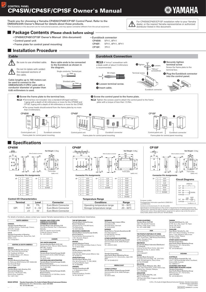
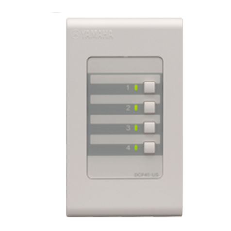
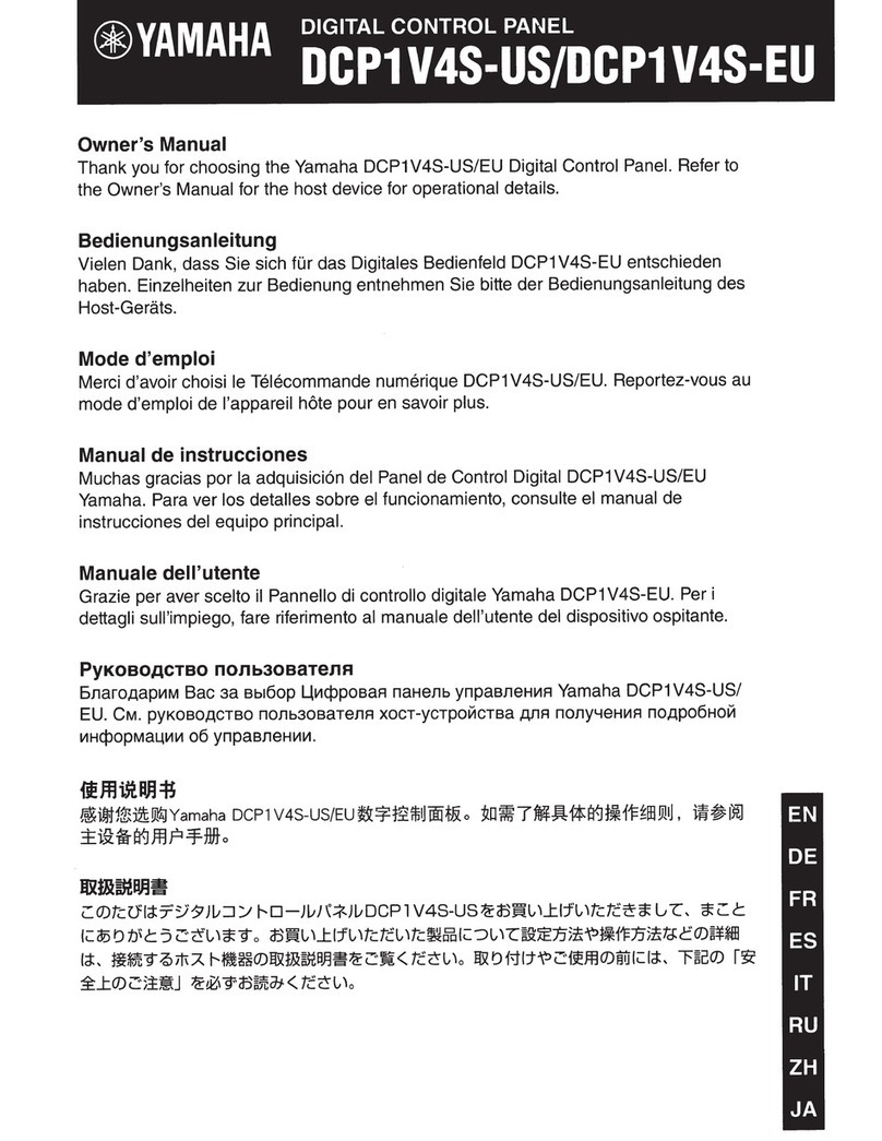
Other manuals for ICP1
5
Table of contents
Other Yamaha Control Panel manuals

Yamaha
Yamaha ICP1 User manual

Yamaha
Yamaha ICP1 User manual

Yamaha
Yamaha CP1SF User manual

Yamaha
Yamaha ICP1 User manual

Yamaha
Yamaha DCP4V4S-EU User manual

Yamaha
Yamaha DCP4V4S-US User manual

Yamaha
Yamaha CP4SW User manual

Yamaha
Yamaha DCP4S-US User manual

Yamaha
Yamaha ICP1 User manual

Yamaha
Yamaha ICP1 User manual
Popular Control Panel manuals by other brands

Ecler essentials
Ecler essentials eMCONTROL1 user manual

Texecom
Texecom Premier 24 user guide

Microm
Microm FX-3500 Installation and operation manual

Honeywell
Honeywell Domonial CMI Series Installer manual

MOOSE
MOOSE MPI-712a installation instructions

Siemens
Siemens SIMATIC HMI KP400 Comfort operating instructions