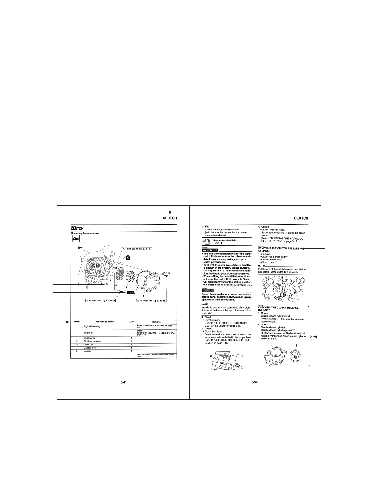
Yamaha FJR13AEV(C) User manual

SERVICE MANUAL
FJR13AV(C)
FJR13AEV(C)
LIT-11616-19-83 3P6-28197-10

EAS20050
FJR13AV(C)/FJR13AEV(C)
SERVICE MANUAL
©2006 by Yamaha Motor Corporation, U.S.A.
First edition, April 2006
All rights reserved.
Any reproduction or unauthorized use
without the written permission of
Yamaha Motor Corporation, U.S.A.
is expressly prohibited.
Printed in U.S.A.
P/N LIT-11616-19-83

EAS20070
NOTICE
This manual was produced by the Yamaha Motor Company, Ltd. primarily for use by Yamaha dealers
and their qualified mechanics. It is not possible to include all the knowledge of a mechanic in one man-
ual. Therefore, anyone who uses this book to perform maintenance and repairs on Yamaha vehicles
should have a basic understanding of mechanics and the techniques to repair these types of vehicles.
Repair and maintenance work attempted by anyone without this knowledge is likely to render the vehi-
cle unsafe and unfit for use.
This model has been designed and manufactured to perform within certain specifications in regard to
performance and emissions. Proper service with the correct tools is necessary to ensure that the vehi-
cle will operate as designed. If there is any question about a service procedure, it is imperative that you
contact a Yamaha dealer for any service information changes that apply to this model. This policy is
intended to provide the customer with the most satisfaction from his vehicle and to conform to federal
environmental quality objectives.
Yamaha Motor Company, Ltd. is continually striving to improve all of its models. Modifications and sig-
nificant changes in specifications or procedures will be forwarded to all authorized Yamaha dealers and
will appear in future editions of this manual where applicable.
NOTE:
• This Service Manual contains information regarding periodic maintenance to the emission control sys-
tem. Please read this material carefully.
• Designs and specifications are subject to change without notice.
EAS20080
IMPORTANT MANUAL INFORMATION
Particularly important information is distinguished in this manual by the following.
The Safety Alert Symbol means ATTENTION! BECOME ALERT! YOUR
SAFETY IS INVOLVED!
Failure to follow WARNING instructions could result in severe injury or death
to the vehicle operator, a bystander or a person checking or repairing the ve-
hicle.
A CAUTION indicates special precautions that must be taken to avoid dam-
age to the vehicle.
A NOTE provides key information to make procedures easier or clearer.
WARNING
CAUTION:
NOTE:

EAS20090
HOW TO USE THIS MANUAL
This manual is intended as a handy, easy-to-read reference book for the mechanic. Comprehensive
explanations of all installation, removal, disassembly, assembly, repair and check procedures are laid
out with the individual steps in sequential order.
• The manual is divided into chapters and each chapter is divided into sections. The current section title
“1” is shown at the top of each page.
• Sub-section titles “2” appear in smaller print than the section title.
• To help identify parts and clarify procedure steps, there are exploded diagrams “3” at the start of each
removal and disassembly section.
• Numbers “4” are given in the order of the jobs in the exploded diagram. A number indicates a disas-
sembly step.
• Symbols “5” indicate parts to be lubricated or replaced.
Refer to “SYMBOLS”.
• A job instruction chart “6” accompanies the exploded diagram, providing the order of jobs, names of
parts, notes in jobs, etc.
• Jobs “7” requiring more information (such as special tools and technical data) are described sequen-
tially.
3
4
5
6
1
2
7

EAS20100
SYMBOLS
The following symbols are used in this manual
for easier understanding.
NOTE:
The following symbols are not relevant to every
vehicle.
GM
E
BLS M
91011
12 13 14
15 16
LT New
T
R
.
.
123
456
78
1. Serviceable with engine mounted
2. Filling fluid
3. Lubricant
4. Special tool
5. Tightening torque
6. Wear limit, clearance
7. Engine speed
8. Electrical data
9. Engine oil
10. Gear oil
11.Molybdenum-disulfide oil
12.Wheel-bearing grease
13.Lithium-soap-based grease
14.Molybdenum-disulfide grease
15.Apply locking agent (LOCTITE®)
16.Replace the part


1
GENERAL INFORMATION
IDENTIFICATION ............................................................................................ 1-1
VEHICLE IDENTIFICATION NUMBER..................................................... 1-1
MODEL LABEL ......................................................................................... 1-1
FEATURES ..................................................................................................... 1-2
OUTLINE OF THE FI SYSTEM................................................................. 1-2
FI SYSTEM ............................................................................................... 1-3
OUTLINE OF THE UNIFIED BRAKE SYSTEM ........................................ 1-4
OUTLINE OF THE ABS ............................................................................ 1-5
ABS COMPONENT FUNCTIONS........................................................... 1-10
ABS OPERATION................................................................................... 1-16
ABS SELF-DIAGNOSIS FUNCTION ...................................................... 1-20
ABS WARNING LIGHT AND OPERATION ............................................ 1-22
OUTLINE OF THE YCC-S (Yamaha Chip Controlled-Shift) SYSTEM
(FJR13AE).............................................................................................. 1-23
INSTRUMENT FUNCTIONS................................................................... 1-26
IMPORTANT INFORMATION ....................................................................... 1-30
PREPARATION FOR REMOVAL AND DISASSEMBLY ........................ 1-30
REPLACEMENT PARTS ........................................................................ 1-30
GASKETS, OIL SEALS AND O-RINGS.................................................. 1-30
LOCK WASHERS/PLATES AND COTTER PINS................................... 1-30
BEARINGS AND OIL SEALS.................................................................. 1-31
CIRCLIPS................................................................................................ 1-31
CHECKING THE CONNECTIONS................................................................ 1-32
SPECIAL TOOLS.......................................................................................... 1-33

IDENTIFICATION
1-1
EAS20130
IDENTIFICATION
EAS20140
VEHICLE IDENTIFICATION NUMBER
The vehicle identification number “1”is stamped
into the right side of the steering head pipe.
EAS20150
MODEL LABEL
The model label “1”is affixed to the frame. This
information will be needed to order spare parts.

FEATURES
1-2
EAS20170
FEATURES
ET2C01025
OUTLINE OF THE FI SYSTEM
The main function of a fuel supply system is to provide fuel to the combustion chamber at the optimum
air-fuel ratio in accordance with the engine operating conditions and the atmospheric temperature. In
the conventional carburetor system, the air-fuel ratio of the mixture that is supplied to the combustion
chamber is created by the volume of the intake air and the fuel that is metered by the jet used in the
respective carburetor.
Despite the same volume of intake air, the fuel volume requirement varies by the engine operating con-
ditions, such as acceleration, deceleration, or operating under a heavy load. Carburetors that meter the
fuel through the use of jets have been provided with various auxiliary devices, so that an optimum air-
fuel ratio can be achieved to accommodate the constant changes in the operating conditions of the en-
gine.
As the requirements for the engine to deliver more performance and cleaner exhaust gases increase,
it becomes necessary to control the air-fuel ratio in a more precise and finely tuned manner. To accom-
modate this need, this model has adopted an electronically controlled fuel injection (FI) system, in place
of the conventional carburetor system. This system can achieve an optimum air-fuel ratio required by
the engine at all times by using a microprocessor that regulates the fuel injection volume according to
the engine operating conditions detected by various sensors.
The adoption of the FI system has resulted in a highly precise fuel supply, improved engine response,
better fuel economy, and reduced exhaust emissions. Furthermore, the air induction system (AI sys-
tem) has been placed under computer control together with the FI system in order to realize cleaner
exhaust gases.
1
2
34
5
678
9
11
12
13
14
15
16
17
10
1. Relay unit (fuel pump relay)
2. Lean angle sensor
3. Engine trouble warning light
4. Ignition coil
5. Cylinder identification sensor
6. Fuel pump
7. Air induction system solenoid
8. Intake air pressure sensor
9. Injector
10. Intake air temperature sensor
11.Rear wheel sensor
12.ECU (engine control unit)
13.O2sensor
14.Throttle position sensor
15.Crankshaft position sensor
16.Spark plug
17.Coolant temperature sensor

FEATURES
1-3
ET3P61042
FI SYSTEM
The fuel pump delivers fuel to the fuel injector via the fuel filter. The pressure regulator maintains the
fuel pressure that is applied to the fuel injector at only 324 kPa (3.24 kg/cm², 46.1 psi). Accordingly,
when the energizing signal from the ECU energizes the fuel injector, the fuel passage opens, causing
the fuel to be injected into the intake manifold only during the time the passage remains open. There-
fore, the longer the length of time the fuel injector is energized (injection duration), the greater the vol-
ume of fuel that is supplied. Conversely, the shorter the length of time the fuel injector is energized
(injection duration), the lesser the volume of fuel that is supplied.
The injection duration and the injection timing are controlled by the ECU. Signals that are input from the
throttle position sensor, coolant temperature sensor, cylinder identification sensor, lean angle sensor,
crankshaft position sensor, intake air pressure sensor, intake air temperature sensor, rear wheel sensor
and O2sensor enable the ECU to determine the injection duration. The injection timing is determined
through the signals from the crankshaft position sensor. As a result, the volume of fuel that is required
by the engine can be supplied at all times in accordance with the driving conditions.
1
15
14
B
13
12
11
10
9
A
238
4
C6
5
7
#3#1 #2 #4
1. Fuel pump
2. Injector
3. Cylinder identification sensor
4. ECU (engine control unit)
5. Throttle position sensor
6. Rear wheel sensor
7. Lean angle sensor
8. O2sensor
9. Catalytic converter
10. Coolant temperature sensor
11.Crankshaft position sensor
12.Intake air pressure sensor
13. Throttle body
14. Intake air temperature sensor
15.Air filter case
A. Fuel system
B. Air system
C. Control system

FEATURES
1-4
ET3P61050
OUTLINE OF THE UNIFIED BRAKE SYSTEM
The Yamaha unified brake system is a system that operates one set of pistons in the front brakes to-
gether with the rear brake when the brake pedal is depressed. Compared to conventional brake sys-
tems, the ability to slow the vehicle using the simple operation of the brake pedal is improved.
Unified brake system block diagram
When the brake lever is squeezed, both sets of pistons in the left front brake caliper are operated, but
only one set of pistons in the right front brake caliper is operated. When the brake pedal is depressed,
the rear brake caliper and one set of pistons in the right front brake caliper are operated. The brake line
from the rear brake master cylinder is split at the hydraulic unit to transmit brake fluid pressure to both
the rear brake caliper and part of the right front brake caliper in the unified brake system. The brake
fluid pressure transmitted to the rear brake caliper and part of the right front brake caliper is controlled
by the proportioning valve and metering valve respectively. The operation of these two valves ensures
that the braking feeling of conventional brakes is maintained when a small amount of force is applied
to the brake pedal, such as when making U-turns, and prevents early locking of the rear wheel when a
large amount of force is applied.
12
3
4
5
6
78
1. Rear brake master cylinder
2. Front brake master cylinder
3. Rear brake caliper
4. Proportioning valve
5. Hydraulic unit
6. Metering valve
7. Left front brake caliper
8. Right front brake caliper

FEATURES
1-5
Brake pedal input force and braking force at each wheel
Metering valve
This valve prevents the brake fluid pressure that is transmitted to the right front brake caliper from in-
creasing until the pressure exceeds a set level. Only the rear brake caliper is operated when there is
an extremely low amount of brake pedal input.
Proportioning valve
This valve reduces the increase in brake fluid pressure that is transmitted to the rear brake caliper when
the pressure exceeds a set level. The increase in brake fluid pressure to the rear brake caliper is con-
trolled when there is a high amount of brake pedal input.
CAUTION:
EC3P61017
• The unified brake system is a system to assist the brake operation. However, both the brake
lever and the brake pedal must be operated for maximum braking effect.
• Because the balance between the right front brake caliper and the rear brake caliper in the uni-
fied brake system is determined mechanically, be sure to use the specified brake pads.
• Each set of brake pads should be checked individually and replaced if necessary.
ET3P61019
OUTLINE OF THE ABS
1. The Yamaha ABS (anti-lock brake system) features an electronic control system, which acts on the
front and rear brakes independently. However, one set of pistons in the right front brake caliper is
operated together with the rear brake and this set of pistons is operated only if the force used to de-
press the brake pedal exceeds a preset level.
2. The ABS features a compact and lightweight design to help maintain the basic maneuverability of
the vehicle.
3. The hydraulic unit, which is the main component of the ABS, is centrally located on the vehicle to
increase mass centralization.
c
d
ee
ff
a
b
a. Brake force
b. Brake pedal force
c. Rear brake force
d. Front brake force (unified brake system)
e. Proportioning valve operation
f. Metering valve operation

FEATURES
1-6
ABS layout
ABS
The operation of the Yamaha ABS brakes is the same as conventional brakes on other vehicles, with
a brake lever for operating the front brake and a brake pedal for operating the rear brake. However, part
of the front brake is operated together with rear brake.
When wheel lock is detected during emergency braking, hydraulic control is performed by the hydraulic
system on the front and rear brakes independently.
Useful terms
•Wheel speed:
The rotation speed of the front and rear wheels.
•Chassis speed:
The speed of the chassis.
When the brakes are applied, wheel speed and chassis speed are reduced. However, the chassis
travels forward by its inertia even though the wheel speed is reduced.
•Brake force:
The force applied by braking to reduce the wheel speed.
•Wheel lock:
A condition that occurs when the rotation of one or both of the wheels has stopped, but the vehicle
continues to travel.
•Side force:
The force on the tires which supports the vehicle when cornering.
4567
8
9
10
11,12
13
14
1
2
3
A
A
15
16 57
1. ABS test coupler
2. ABS warning light
3. ABS ECU fuse
4. ABS motor fuse
5. ABS motor relay
6. ABS ECU (electronic control unit)
7. Hydraulic unit (HU)
8. Rear wheel sensor
9. Rear wheel sensor rotor
10.Rear brake caliper
11.Left front brake caliper
12.Right front brake caliper (partially operated
together with the rear brake)
13.Front wheel sensor
14.Front wheel sensor rotor
15.Proportioning valve
16.Metering valve

FEATURES
1-7
•Slip ratio:
When the brakes are applied, slipping occurs between the tires and the road surface. This causes a
difference between the wheel speed and the chassis speed.
Slip ratio is the value that shows the rate of wheel slippage and is defined by the following formula.
0%: There is no slipping between the wheel and the road surface. The chassis speed is equal to the
wheel speed.
100%: The wheel speed is “0”, but the chassis is moving (i.e., wheel lock).
Brake force and vehicle stability
When the brake pressure is increased, wheel speed is reduced. Slipping occurs between the tire and
the road surface and brake force is generated. The limit of this brake force is determined by the friction
force between the tire and the road surface and is closely related to wheel slippage. Wheel slippage is
represented by the slip ratio.
Side force is also closely related to wheel slippage. See figure A. If the brakes are applied while keeping
the proper slip ratio, it is possible to obtain the maximum brake force without losing much side force.
ABS allows full use of the tires’capabilities even on slippery road surfaces or less slippery road surfac-
es. See figure B.
Wheel slip and hydraulic control
The ABS ECU calculates the wheel speed of each wheel according to the rotation signal received from
the front and rear wheel sensors. In addition, the ABS ECU calculates the vehicle chassis speed and
the rate of speed reduction based on the wheel speed values.
Slip ratio =
Chassis speed –
Wheel speed ×100 (%)
Chassis speed
b
c
a
A
d
a
e
f
g
d
B
a. Friction force between the tire and road
surface
b. Brake force
c. Side force
d. Slip ratio (%)
e. Less slippery road surface
f. Controlling zone
g. Slippery road surface

FEATURES
1-8
The difference between the chassis speed and the wheel speed calculated in the slip ratio formula is
equal to the wheel slip. When the wheel speed is suddenly reduced, the wheel has a tendency to lock.
When the wheel slip and the wheel speed reduction rate exceed the preset values, the ABS ECU de-
termines that the wheel has a tendency to lock.
If the slip is large and the wheel has a tendency to lock (point A in the following figure), the ABS ECU
reduces the brake fluid pressure in the brake caliper. The ABS ECU increases the pressure of the brake
fluid in the brake caliper when the tendency to lock has diminished (point B in the following figure).
ABS operation and vehicle control
If the ABS starts operating, there is a tendency of the wheel to lock, and the vehicle is approaching the
limit of control. To make the rider aware of this condition, the ABS has been designed to generate a
reaction-force pulsating action in the brake lever and brake pedal independently.
NOTE:
When the ABS is activated, a pulsating action may be felt at the brake lever or brake pedal, but this
does not indicate a malfunction.
The higher the side force on a tire, the less traction there is available for braking. This is true whether
the vehicle is equipped with ABS or not. Therefore, sudden braking while cornering is not recommend-
ed. Excessive side force, which ABS cannot prevent, could cause the tire to slip sideways.
WARNING
EW3P61003
The braking of the vehicle, even in the worst case, is principally executed when the vehicle is
advancing straight ahead. During a turn, sudden braking is liable to cause a loss of traction of
the tires. Even in vehicles equipped with ABS, overturning of the vehicle cannot be prevented
if it is braked suddenly.
The ABS functions to prevent the tendency of the wheel to lock by controlling the brake fluid pressure.
However, if there is a tendency of the wheel to lock on a slippery road surface, due to engine braking,
the ABS may not be able to prevent the wheel from locking.
a
b
c
d
e
a. Chassis speed
b. Wheel speed
c. Pressurized
d. Depressurized
e. Brake force

FEATURES
1-9
WARNING
EWA13870
The ABS controls only the tendency of the wheel to lock caused by applying the brakes. The
ABS cannot prevent wheel lock on slippery surfaces, such as ice, when it is caused by engine
braking, even if the ABS is operating.
Electronic ABS features
The Yamaha ABS (anti-lock brake system) has been developed with the most advanced electronic
technology.
The ABS control is processed with good response under various vehicle travel conditions.
The ABS also includes a highly developed self-diagnosis function. The ABS detects any problem con-
dition and allows normal braking even if the ABS is not operating properly.
When this occurs, the ABS warning light on the meter assembly comes on.
The ABS stores the malfunction codes in the memory of the ABS ECU for easy problem identification
and troubleshooting.
a. Friction force between the tire and road
surface
b. Brake force
c. Side force
d. Slip ratio (%)

FEATURES
1-10
ABS block diagram
ET3P61051
ABS COMPONENT FUNCTIONS
Wheel sensors and wheel sensor rotors
Wheel sensors “1”detect the wheel speed and transmit the rotation signal to the ABS ECU.
Each wheel sensor is composed of a permanent magnet and a coil. The wheel sensors are installed in
the sensor housing for each wheel. Sensor rotors “2”are pressed in the inner side of the front and rear
wheel hubs and rotate with the wheels. The wheel sensor rotors have 42 serrations inside and are in-
stalled close to the wheel sensors. As the distance changes between the top and bottom of the serra-
tions with the rotation of the wheels, inductive electromotive force is generated in the wheel sensors.
Wheel speed is detected based on the frequency of this alternating voltage.
1
877
6
54
2
5
6
7
3
13
14
15
16
12
11
10
9
1. Rear brake master cylinder
2. Hydraulic unit
3. Front brake master cylinder
4. ABS motor
5. Hydraulic pump
6. Buffer chamber
7. Hydraulic control valve
8. Proportioning valve
9. Rear brake caliper
10.Rear wheel sensor
11.Metering valve
12.ABS ECU
13.Left front brake caliper
14.Front wheel sensor
15.Right front brake caliper
16.ABS warning light
1
2
1
2

FEATURES
1-11
ABS warning light
The ABS warning light “1”comes on to warn the rider if a malfunction in the ABS occurs.
When the main switch is turned to “ON”, the ABS warning light comes on for 2 seconds, then goes off,
so that the rider can check if the ABS warning light is disconnected and check if the ABS is operating
properly.
CAUTION:
EC3P61009
If the rear wheel is raced with the vehicle on the centerstand, the ABS warning light may flash
or come on. If this occurs, turn the main switch to “OFF”, then back to “ON”. The ABS operation
is normal if the ABS warning light comes on for 2 seconds, then goes off.
Hydraulic unit
The hydraulic unit “1”is composed of three hydraulic control valves (each with a solenoid valve and flow
control valve), two buffer chambers, two hydraulic pumps, and an ABS motor. The hydraulic unit adjusts
the front and rear wheel brake fluid pressure to control the wheel speed according to signals transmitted
from the ABS ECU.
•Hydraulic control valve
The hydraulic control valve is composed of a flow control valve and solenoid valve.
3. At high speed
4. At low speed
5. Wheel sensor rotor
6. Wheel sensor
1
1
Other manuals for FJR13AEV(C)
1
This manual suits for next models
1
Table of contents
Popular Farm Equipment manuals by other brands

Wacker Neuson
Wacker Neuson GreenTec 1402 Handbook

Ziegler
Ziegler PKT 450 Operating instructions and spare parts list

Farmi Forest Corporation
Farmi Forest Corporation VARIO 101 Operating, Maintenance and Spare Parts Manual

Landoll
Landoll 3631-30 Operator's manual

Michel's
Michel's EZ-Lift instructions

AGCO
AGCO FENDT 9300R Operator's manual

EASY COOPS
EASY COOPS 5x6 Chicken Coop Plan manual

breviglieri
breviglieri MEKFARMER 80 Operating and maintenance manual

Hisarlar
Hisarlar SB1150 User and maintenance manual

Gronomics
Gronomics CCPC 45-45 Assembly instruction

Croplands
Croplands AgriPak LA300 Operator's manual

Claas
Claas AVERO Information and Basic Field Settings