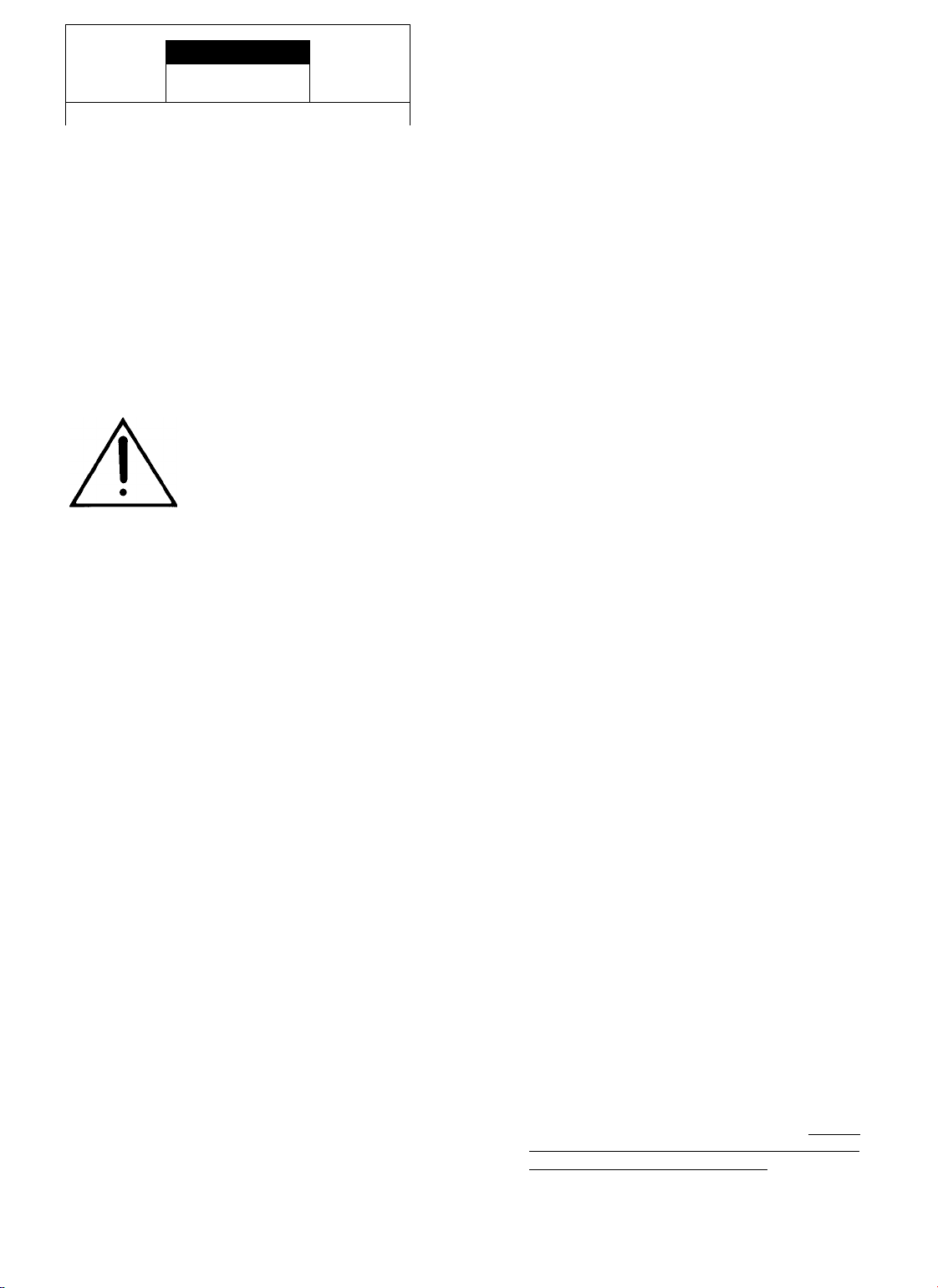
A
CAUTION
A
RISK OF ELECTRIC SHOCK
DO NOT OPEN
—
CAUTION: TO REDUCE THE RISK OF ELECTRIC SHOCK.
DO NOT REMOVE COVER (OR BACK).
NO USER-SERVICEABLE PARTS INSIOE.
REFER SERVICING TO QUALIFIED SERVICE PERSONNEL.
Explanation of Graphical ymbols
A The lightning flash with a owhead
symbol, within an equilate al t iangle, is
intended to ale t you to the p esence of
uninsulated “dange ous voltage” within
the p oduct’s enclosu e that may be of
■ sufficient magnitude to constitute a isk of
elect ic shock to pe sons.
The exclamation point within an
equilate al t iangle is intended to ale t you
to the p esence of impo tant ope ating
and maintenance (se vicing) inst uctions
in the lite atu e accompanying the
appliance.
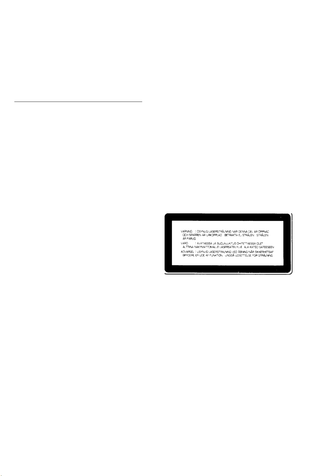
DANGER
Invisible lase adiation when open and inte lock failed o
defeated.
Avoid di ect exposu e to beam.
CAUTION
Use of cont ols o adjustments o pe fo mance of p ocedu es
othe than those specified he ein may esult in haza dous
adiation exposu e.
Laser Diode Properties
• Mate ial: GaAIAs
• Wavelength: 780nm
• Emission Du ation: continuous
• Lase Output: max. 44.6pW*
• This output is the value measu ed at a distance of about
200mm f om the objective lens su face on the Optical Pick
up Block.
WARNING: CHEMICAL CONTENT NOTICE!
The solde used in the manufactu e of this p oduct contains
LEAD. In addition, the elect ical/elect onic and/o plastic (whe e
applicable) components may also contain t aces of chemicals
found by the Califo nia Health and Welfa e Agency (and possibly
othe entities) to cause cance and/o bi th defects o othe
ep oductive ha m.
DO NOT REMOVE ANY ENCLO URE COMPONENT !
The e a e no use se viceable pa ts inside. All se vice should be
pe fo med by a se vice ep esentative autho ized by Yamaha to
pe fo m such sen/ice.
IMPORTANT ME AGE: Yamaha st ives to p oduce
p oducts that a e both use safe and envi onmentally “f iendly”.
We since ely believe that ou p oducts meet these goals.
Howeve , in keeping with both the spi it and the lette of va ious
statutes we have included the messages shown above and
othe s in va ious locations in this manual.
1.
2.
3.
IMPORTANT NOTICE: DO NOT MODIFY THIS UNIT!
This p oduct, when installed as indicated in the inst uctions
contained in this manual, meets FCC equi ements.
Modifications not exp essly app oved by Yamaha may void
you autho ity, g anted by the FCC, to use the p oduct.
IMPORTANT : When connecting this p oduct to accesso ies
and/o anothe p oduct use only high quality shielded cables.
Cable/s supplied with this p oduct MUST be used. Follow all
installation inst uctions. Failu e to follow inst uctions could
void you FCC autho ization to use this p oduct in the USA.
NOTE: This p oduct has been tested and found to comply
with the equi ements listed in FCC Regulations; Pa t 15 fo
Class “A” digital devices. Compliance with these
equi ements p ovides a easonable level of assu ance that
you use of this p oduct in a comme cial envi onment will not
esult in ha mful inte fe ence with othe elect onic devices.
Howeve , ope ation of this p oduct in a esidential a ea is
likely to cause inte fe ence in some fo m. In this case you, the
use , bea the esponsibility of co ecting this condition.
This p oduct gene ates/uses adio f equencies and, if not
installed and used acco ding to the inst uctions found in the
use s manual, may cause inte fe ence ha mful to the
ope ation of othe elect onic devices. Compliance with FCC
FCC INFORMATION (U. .A.)
egulations does not gua antee that inte fe ence will not
occu in all installations. If this p oduct is found to be the
sou ce of inte fe ence, which can be dete mined by
tu ning the unit “OFF” and “ON”, please t y to eliminate the
p oblem by using one of the following measu es:
Relocate eithe this p oduct o the device that is being
affected by the inte fe ence.
Utilize powe outlets that a e on diffe ent b anch (ci cuit
b eake of fuse) ci cuits o install AC line filte /s.
In the case of adio o TV inte fe ence, elocate/ eo ient
the antenna. If the antenna lead-in is 300 ohm ibbon lead,
change the lead-in to co-axial type cable.
If these co ective measu es do not p oduce satisfacto y
esults, please contact the local etaile autho ized to
dist ibute this type of p oduct. If you can not locate the
app op iate etaile , please contact ’‘Yamaha
Co po ation of Ame ica. Elect onic Sen/ice Division. 6600
O anqetho oe Ave. Buena Pa k. CA90620.
The above statements apply ONLY to those p oducts
dist ibuted by Yamaha Co po ation of Ame ica o its
subsidia ies.