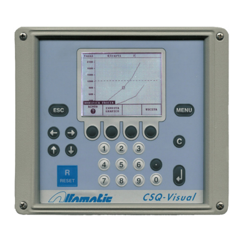
ALFAMATIC CSQ-Visual User manual

Mar. 7, 2017
CSQ-Visual
Version with VIO9 card
Installation manual

2

3
1 Installing CSQ-Visual..................................................................................................................4
1.1
Important notes for installation ...................................................................................................... 4
1.2
Operating of the instrument ............................................................................................................ 4
1.3
Internal cards.................................................................................................................................... 5
1.4
Electric wiring................................................................................................................................... 5
2 Special functions ........................................................................................................................12
2.1
Configure automatic work selection ............................................................................................. 12
2.2
Configuring the use of the phases.................................................................................................. 13
2.3
Connection of an external reset..................................................................................................... 14
2.4
ETPOINT output.......................................................................................................................... 14
3 Instructions for setting up the CSQ-Visual...............................................................................15

4
1 Installing CSQ-Visual
This paragraph describes the operations necessary to fit and connect the CSQ-Visual to the machine
and make it operative.
The CSQ-Visual has been designed to be independent: a you have to do is connect the va ves and
sensors that wi be powered by the instrument. Natura y there’s nothing to stop you from
combined use with a PLC.
To operate, the CSQ-Visual requires different input and output signa s. As regards the inputs, a
force transducer ( oad ce ), a position transducer (incrementa encoder, potentiometer or 0-10 V
transducer) and various sensors are required. The outputs are connected to the unit descent
enab ing va ve, the protection c osure va ve (where insta ed) and the warning ights.
1.1 Important notes for installation
This manua refers on y to the instrument with expansion card VIO9.
The CSQ-Visual has to be powered at 24VDC. An optiona interna power feeder is
avai ab e, enab ing direct connection to the mains power.
This instrument is not (and cou d not be) a safety device: the descent of the press must be
entrusted to e ements outside the instrument. The instrument synchronises the descent of
the press in order for it to work.
It is very important for the oad ce wire termina , which is not sheathed, to be as short as
possib e.
When the machine has e ectric motors, these must be equipped with an anti-interference
fi ter and be contro ed using semiconductor devices.
A ways connect the container of the instrument to the earth conductor.
1.2 Operating of the instrument
Attention: the CSQ-Visual is not (an coul not be) a safety evice: the escent of the press must
be entruste to external elements. The CSQ-Visual synchronises the escent for its operation.
The GO Output is usually connecte serially to the chain of the cylin er escent. In short, if the
CSQ-Visual activates the GO enabling output, the cylin er must not escen if it is not safe.
Operation takes p ace as fo ows: when the START input is activated by an externa command, the
CSQ–Visual, if ready, activates the protection descent output (PROTECTION) where present and
enab es the cy inder descent (GO). When the protection is c osed, a safety device must activate the
cy inder unti the CSQ-Visual removes the cy inder descent enab ing signa (GO). The CSQ-Visual
then commands the arrest of the press, removing the GO signa , contro s the curve unti the force
begins to diminish or is activated by way of the T.D.C. input (withdraw cy inder signa ). On y then
does it indicate whether or not the piece is good or a reject.
If the piece is good, the GOOD output is activated and the PROTECTION output, where present, is
deactivated. If the piece is a reject, the REJECTED output is activated intermittent y and the
PROTECTION output, where present, is eft active. When the operator presses the reset button,
which can be externa or a ways active, the instrument maintains the REJECTED output as fixed
and removes the PROTECTION output.
5
The correct a ignment of the encoder takes p ace using its zero notch and the T.D.C. withdraw
cy inder signa .
1.3 Internal cards
There are two cards inside the CSQ–Visual:
frontal (CSQVMB) supports the disp ay, keyboard and main CPU.
input e output (VIO) for the connection of input signa s, output signa s and transducers.
We make a the cards ourse ves and they can be a tered to suit your specific requirements.
1.4 Electric wiring
The fo owing information exp ains how to insta the e ectric wiring.
1.4.1 Information for connection to an external controller (PL )
To connect the CSQ-Visual to a PLC, the atter must have PNP positive ogic. The inputs and
outputs of the instrument are optoinsu ated from the instrument’s contro e ectronics. The power
supp y of the instrument’s inputs and outputs must be the same that powers the inputs and outputs
of the PLC. We recommend the use of at east one output (START signa ) and three inputs of the
PLC (GO, GOOD and REJECTED). If necessary, with the press contro ed direct y by the
instrument, it is possib e to use a sing e input to know whether the piece is good (GOOD output)
and a sing e output to contro the start of the pressing cyc e (START input).
Remember that, in a cases, it is a ways necessary too connect the T.D.C. input of the CSQ-Visual.
The T.D.C. signa can be acquired direct y by a imit switch activated with the press in the resting
position. However, the signa indicating that the press is in the resting position is a most a ways
used by the PLC. In this case the signa to be given to the instrument may be taken para e to that
de ivered to the PLC.
1.4.2 VIO9 card wiring
Attention: this information refers only to the VIO9 card. Check that the correct type of card is
fitted.

6
The wiring is supported by removab e termina b ocks (X3, X4, X16...). Every termina on every
termina b ock is numbered. For examp e, when termina X18.7 is indicated, reference is made to
the seventh termina of termina b ock X18. The numbers are a so printed on the printed circuit of
the card.
Figure 1
Main power terminal block (X24)
The e ectronics of the CSQ-Visual and the transducers are powered at 24VDC via the X24 three-
po e termina b ock.
Name Function Termina
0VDC Negative power X24.1
PE Earth connection X24.2
+24VDC Positive power X24.3
If the interna power feeder is fitted, the switch behind the instrument has to interrupt the phase and
neutra before reaching the power feeder. The power feeder output must be connected to termina
b ock X24.

7
Inputs terminal block (X3)
The inputs are optoinsu ated and compatib e with c ean contact signa s or 24 VDC PNP transistor
outputs.
Name Terminal Default
Input 0 X3.1 START
Input 8 X3.2
Input 1 X3.3 T.D. .(1)
Input 9 X3.4
Input 2 X3.5
Input 3 X3.6
Input 4 X3.7
Input 5 X3.8
Input 6 X3.9
Input 7 X3.10
0VD X3.11 Negative power supply
+24VD X3.12 Positive power supply
(1) T.D.C. input in a ways on input 1.
The function of each input is configurab e. Each input can have one of the fo owing functions:
Name Default Function
START 0 Request for starting a new cycle. If remove the acquisition is stopped.
T.D. .(1) 1 Signal "top dead center", used as a reset for a new cycle and ANDed with
the zero mark of the encoder to the zeroing the absolute position
JOB SELE TOR The binary value of these inputs select automatically a jobs (see 2).
PHASE SELE TOR The binary value of these inputs select automatically the phase of job.
BASKET 1 2 Input for sensor for the detection of normal rejected (basket)
BASKET 2 3 Input for sensor for the detection of special rejected (basket)
BASKET AUTO- HE K Input for sensor for the detection of auto-check samples (basket)
RESET 2 Re-enable the instrument after a rejected
SESPEND A QUIRE Suspends the acquisition of the curve useful in hydraulic presses in case
of stop in halfway.
ENABLE # See 2.4
TEST SIGNAL # #1=4 See 2.4
BOOSTER YL BA K Used for the repetition of the working stroke
BOOSTER YL END Used for the repetition of the working stroke
MAINTENAN E 5 Disable all controls
TABLE IN POS Signal for piece in the working position
IMPULSIVE START Left=6
Right=7
Request for start of a new cycle
NO EMERGEN Y Machine is not in emergency
SAFETY Machine security (guards closed)
DRIVER ATIVATE Driver actived (servo presses)
IN POSITION Position reached (servo presses)
(1) T.D.C. input in a ways on input 1.

8
Outputs terminal block (X4)
Outputs for 24VDC oads. For inductive oads such as va ves and re ays, it is necessary to have a
diode para e to the coi s to e iminate peaks in vo tage.
Nome Morsetto Default
Output 0 X4.1 GOOD
0V X4.2 Negative power supply
Output 1 X4.3 REJE TED 1
Output 8 X4.4
Output 2 X4.5 PRESS
Output 3 X4.6 PROTE TION
Output 4 X4.7 ONTA T/BOOSTER
Output 5 X4.8
Output 6 X4.9
Output 7 X4.10
The function of each output is configurab e. Each output can have one of the fo owing functions:
Name Default Function
GOOD 0 Good piece signal. Active after the return of the cylinder until the next
start.
REJE TED 1 1 Normal rejected piece signal. Active after the return of the cylinder until
the next start. The output is intermittent until the reset signal.
REJE TED 2 7 Special rejected piece signal. Active after the return of the cylinder until
the next start. The output is intermittent until the reset signal.
REJE TED AUTO- HE K Auto-check sample piece signal. Active after the return of the cylinder
until the next start. The output is intermittent until the reset signal.
PRESS 2 Enables the press. Active after the start if the instrument is ready and
deactivated upon reaching the stoppage value.
DOOR 3 ommand for the closure of the protection
BUZZER 4 ommand for the closure of the acoustic signal.
TEST OUTPUT 6 Activation of external measuring TEST SIGNAL 1
ONTA T/BOOSTER ontact to piece or start working stroke
HE K POINT OUT # Output activated at a programmable position (up to 3 outputs)
PHASE BIT 0 Active when working the phase 2 or 4
PHASE BIT 1 Active when working the phase 3 or 4
MANUAL Active when you choose a job that is not a selectable job
BRAKE Output for a brake to reduce speed
ENABLE RETURN 5 Enable return of the cylinder when detecting a good piece or after reset
ENABLE MANUALE ontrol for electric lock lever on mechanical presses
OPEN GREEN BOX ommand for opening basket of the good pieces
LOSE PK TANK losing command of the tank on the Alfamatic PK cilinders
BLO K OF THE TABLE Block piece for work
PULL LEVER ylinder control help return cylinder (for heavy tools)
RESET DRIVER Driver reset fault (servo presses)
ENABLE DRIVER Driver enable (servo presses)

9
ransducer input terminal block (X12)
An incrementa encoder and a 0-10V signa can be connected to the X12 termina b ock. A 12VDC
or 5VDC power supp y is avai ab e for the encoder (jumper J3). A very high-precision 10VDC
power supp y is avai ab e for the potentiometer.
Name Terminal Description
Phase Z X12.1 PHASE Z signal
Phase B X12.2 PHASE B signal
Phase A X12.3 PHASE A signal
+VD encoder X12.4 Encoder power supply J3A*=12V J3B=5V
0VD X12.5 GND
AN- (0V) X12.6 Negative analog differential input (with J8 this imput is internal
connected to 0V)
+10V X12.7 10V potentiometer power (10mA max)
POT+ X12.8 Positive analog differential input (potentiometer cursor) (with J4 this
imput accept 0-20mA signal)
E ectrica features of termina s X12.1, X12.2 and X12.3
Ana og input type on X12
J4 J9 J11 J12
0-10V* OUT IN IN OUT
0-5V OUT OUT IN OUT
0-20mA IN IN IN OUT
4-20mA IN IN OUT IN
* default
Load cell terminal block (X11)
Input for oad ce with resistive bridge with a sensitivity of 2mV/V. The power for supp y the oad
ce is a so avai ab e on this termina b ock.
Name Terminal Description
IN+ X11.1 Positive input
IN- X11.2 Negative input
0V X11.3 Power earth
0V X11.4 Screened wire sheath
+VD X11.5 +5V whit J10A or Logic earth whit J10B

10
Ana og input type on X11
J5 J6 J7 J10
Load ce 2mV/V supp y 10V push on y * A A OUT
A
Load ce 2mV/V supp y 10V push pu B OUT
OUT
A
Load ce 2mV/V supp y 5V push pu A OUT
OUT
B
Ana og input 0-10V OUT
B IN A
Ana og input 0-5V OUT
B OUT
B
* default
ypical connection

11
Optional connector D-Sub RS232
The RS232 pinout:
Pin 2: RX interface input signal to the CSQ-Visual.
Pin 3: TX interface output signal from the CSQ-Visual.
Pin 5: GND
Optional analog outputs (X16)
...
Nome Morsetto Descrizione
LK+ X16.1 Do not connect
LK- X16.2 Do not connect
DIR+ X16.3 Do not connect
DIR- X16.4 Do not connect
ANA2 X16.5 Analog output 2
ANA1 X16.6 Analog output 1
0V X16.7 GND

12
2 Special functions
.
2.1 onfigure automatic work selection
The CSQ-Visual supports the automatic se ection of work using the combination of the inputs or a
command sent to the seria port. This se ection can be usefu for automatica y recognising the
piece or the too fitted.
To enab e the automatic se ection of work it is necessary to give the instrument the maximum
number of se ectab e works and the way in which they are se ected.
To do this, se ect the
TOOLS > ADVAN ED OPTIONS > MA HINE TYPE > WORKS PHASES
HANNELS
menu and change the Number of selectable works va ue; then indicate the se ection
mode, changing the Automatic selection code.
After changing the configuration, the instrument wi create the se ectab e works, initia y empty; to
make an empty work suitab e for use, use the
WORKS MANAGEMENT > HANGE WORK
command
and press enter on the work required. Now change the name of the work. The
REATE NEW WORK
item in the
WORKS MANAGEMENT
menu enab es the creation of extra works which can be used
separate y from the work se ected automatica y; to create an extra work and use a work other than
that se ected automatica y the un ock password in required.
Automatic se ection on y works if the instrument START input is not active.
2.1.1 Selection through inputs
The work number is obtained from the binary combination of the inputs. The binary code of the
first work is zero, i.e.: no input active. The maximum number of se ectab e works, if enough inputs
are avai ab e, is 64 (with binary codes from 0 to 63).
The wiring is connected to a termina b ock inside the instrument marked X3.
The highest inputs must be used for se ection.
Example: assuming the use of the CSQVIO card, which has 8 inputs, if it is necessary to se ect a
maximum of 4 works, inputs 7 and 8 wi be used: input 8 wi be the east significant bit, whi e
input 7 wi be the most significant.
2.1.1.1 onnection of sensors for work selection
It is possib e to use positive ogic sensors (PNP) or c ean contacts for connection to positive.
For examp e, if it is necessary to connect 4 sensors to the instrument (se ection from 9 to 16 works)
which has 8 inputs, inputs 5, 6, 7 and 8 must be used. Input 8 wi be the east significant bit, whi e
input 5 wi be the most significant.

13
Examp e of wiring of three sensors (se ection of 5 to 8 works):
2.1.2 Selection through serial command
The CSQ-Visual supports seria communication through which it is possib e to se ect a work
remote y. Using seria communication, it is possib e to se ect up to 250 works. To be ab e to
operate it is necessary to enab e s ow seria communication and set the Automatic selection code.
For the use of seria communication, see the re ative manua .
2.2 onfiguring the use of the phases
It is sometimes necessary to perform different machining process on the same piece, for instance,
different gears are fitted onto a drive shaft one after the other: hence the need to ana yse a the
different machining phases.
The CSQ-Visual is ab e to manage up to four phases for each sing e process. The choice of the
phase may take p ace automatica y, in succession or through the digita inputs of the instrument.
For every work process is it possib e to decide whether to exc ude one or more phases.
To enab e a function for severa phases, it is necessary to indicate the maximum number of phases
supported. To do this, se ect the
TOOLS > ADVANCED OPTIONS > MACHINE TYPE > WORKS
PHASES CHANNELS
menu and change the Number of phases va ue. As we as indicating the
number of phases, it is necessary to indicate the way to behave, changing the Automatic selection
code.
If the maximum number of phases is changed, it wi be necessary to cance a the works created
previous y:
Figure 2

14
If required, it is possib e to save them first on the computer using the inScope program.
2.3 onnection of an external reset
When a reject is detected, the instrument b ocks, preventing the machining of other pieces. The
re ease the instrument it is necessary to reset the reject. It is possib e to connect an externa reset
signa which can be a button, key or sensor. The reset signa can be eft active at a times to have
the autoreset function. Like a the other inputs, the reset signa has to have a 24VDC c ean contact
or an e ectronic sensor with a PNP (positive ogic) output.
2.4 SETPOINT output
The CSQ-Visual has an auxi iary output which can be activated when a determined abso ute
position or a determined force have been reached. The va ue of this position or force of the
setpoint can be different for every sing e work.
Once the abso ute position or force va ue has been reached, the output is activated and kept active
unti the press stops.
With the CSQ Visual Setup program it is possib e to assign a descriptive name to this output.
This output is norma y used to command a hydrau ic brake or the start of the press power.
Natura y it can be used for any other function.
To set the setpoint activation thresho d use the
CHANGE WORK > PARAMETERS > OTHER LIMITS
command.

15
3 Instructions for setting up the CSQ-Visual
Always disconnect the instrument from the electricity supply before opening it.
Open the CSQ-Visual by oosening the four screws in the corners of the front pane .
Figure 3
Pu out the interna cards by a few centimetres. Then re ease the cards from the front pane .
Figure 4
Pu out a the cards from the container and remove the five termina b ock units.
To fasten the instrument in p ace it is possib e to perforate the container on the top or bottom (after
removing a the cards) in the midd e.
Fit the wire passage and p ugs. To fit a arger wire passage, the ho e C8 can be en arged using a
stepped cutter.

16
Figure 5
S ot the wires through the wire passage and start wiring.
It is extremely important for the end of the wire of the load cell which is not covered by a
sheath to be as short as possible
After comp eting the wiring, insert the card
Last y, insert the termina b ock units, paying attention to the direction.
Make sure that cables are not squashed on the bottom of the instrument.
After comp eting the wiring it is possib e to supp y power to the instrument, switching it on using
the switch on the back and proceeding as fo ows:
• Configure the instrument.
• Check the operation of the inputs and outputs, using the contro s of the
DIAGNOSIS
menu.
• Ca ibrate the transducers.
Other manuals for CSQ-Visual
2
Table of contents
Other ALFAMATIC Measuring Instrument manuals

ALFAMATIC
ALFAMATIC Press-Right User manual

ALFAMATIC
ALFAMATIC PRESS -RIGHT User manual

ALFAMATIC
ALFAMATIC CSQ-Visual User manual

ALFAMATIC
ALFAMATIC Press-Right User manual

ALFAMATIC
ALFAMATIC Press-Right User manual

ALFAMATIC
ALFAMATIC CSQVIO8 User manual

ALFAMATIC
ALFAMATIC Press-Right User manual

ALFAMATIC
ALFAMATIC Visual Point User manual