manuals.online logo
Brands
  1. Home
  2. •
  3. Brands
  4. •
  5. Yamaha
  6. •
  7. Synthesizer
  8. •
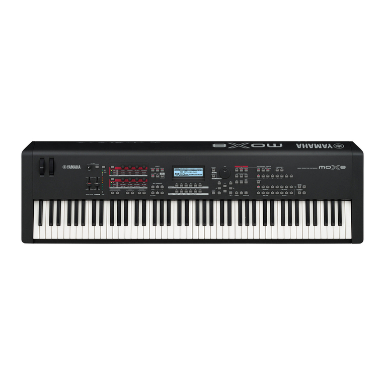
  9. Yamaha PSR-170 User manual

Yamaha PSR-170 User manual

Other manuals for PSR-170

1

Other Yamaha Synthesizer manuals

Yamaha S90 XS Editor VST S70 XS Editor VST User manual

Yamaha

Yamaha S90 XS Editor VST S70 XS Editor VST User manual

Yamaha YFP-70 User manual

Yamaha

Yamaha YFP-70 User manual

Yamaha CS01 User manual

Yamaha

Yamaha CS01 User manual

Yamaha S90 XS Editor VST S70 XS Editor VST User manual

Yamaha

Yamaha S90 XS Editor VST S70 XS Editor VST User manual

Yamaha RX-11 User manual

Yamaha

Yamaha RX-11 User manual

Yamaha PF-1000 User manual

Yamaha

Yamaha PF-1000 User manual

Yamaha TX816 Manual

Yamaha

Yamaha TX816 Manual

Yamaha MX49 User manual

Yamaha

Yamaha MX49 User manual

Yamaha MX49 Instruction Manual

Yamaha

Yamaha MX49 Instruction Manual

Yamaha MOX8 User manual

Yamaha

Yamaha MOX8 User manual

Yamaha DX11 User manual

Yamaha

Yamaha DX11 User manual

Yamaha JOGR JOGRR CS50 User manual

Yamaha

Yamaha JOGR JOGRR CS50 User manual

Yamaha S90 XS Editor VST S70 XS Editor VST User manual

Yamaha

Yamaha S90 XS Editor VST S70 XS Editor VST User manual

Yamaha CS-20M User manual

Yamaha

Yamaha CS-20M User manual

Yamaha S70 XS User manual

Yamaha

Yamaha S70 XS User manual

Yamaha Harmony Director HD-200 User manual

Yamaha

Yamaha Harmony Director HD-200 User manual

Yamaha S08 Voice Editor User manual

Yamaha

Yamaha S08 Voice Editor User manual

Yamaha CS1X Assembly instructions

Yamaha

Yamaha CS1X Assembly instructions

Yamaha YPP-45 User manual

Yamaha

Yamaha YPP-45 User manual

Yamaha VL-1 User manual

Yamaha

Yamaha VL-1 User manual

Yamaha PSR-S975 User manual

Yamaha

Yamaha PSR-S975 User manual

Yamaha SY-77 User manual

Yamaha

Yamaha SY-77 User manual

Yamaha CS-15 User manual

Yamaha

Yamaha CS-15 User manual

Yamaha CP-30 User manual

Yamaha

Yamaha CP-30 User manual

Popular Synthesizer manuals by other brands

NEON CAPTAIN Radioator user manual

NEON CAPTAIN

NEON CAPTAIN Radioator user manual

Roland JD-800 owner's manual

Roland

Roland JD-800 owner's manual

Joranalogue Contour 1 user manual

Joranalogue

Joranalogue Contour 1 user manual

Full Bucket Music Mono/Fury manual

Full Bucket Music

Full Bucket Music Mono/Fury manual

IK Multimedia UNO Synth PRO X user manual

IK Multimedia

IK Multimedia UNO Synth PRO X user manual

Kawai MP7 Software update

Kawai

Kawai MP7 Software update

Roland Gaia SH-01 Quick guidebook

Roland

Roland Gaia SH-01 Quick guidebook

Behringer DEEPMIND 12 quick start guide

Behringer

Behringer DEEPMIND 12 quick start guide

Roland GR-30 manual

Roland

Roland GR-30 manual

Moog Minitmoog 300A Owner's service manual

Moog

Moog Minitmoog 300A Owner's service manual

Gotharman Gotharman's anAmoNo-box user manual

Gotharman

Gotharman Gotharman's anAmoNo-box user manual

QuStream HDFS-550 Technical manual

QuStream

QuStream HDFS-550 Technical manual

Akai AX80 Operator's manual

Akai

Akai AX80 Operator's manual

Roland GS-500 instructions

Roland

Roland GS-500 instructions

Octave Cat SRM Service manual

Octave

Octave Cat SRM Service manual

Dreadbox Murmux Initiate manual

Dreadbox

Dreadbox Murmux Initiate manual

neutral labs ELMYRA 2 Build guide

neutral labs

neutral labs ELMYRA 2 Build guide

Waldorf KYRA user manual

Waldorf

Waldorf KYRA user manual

manuals.online logo
manuals.online logoBrands
  • About & Mission
  • Contact us
  • Privacy Policy
  • Terms and Conditions

Copyright 2025 Manuals.Online. All Rights Reserved.

SERVICE MANUAL
■ CONTENTS
SPECIFICATIONS.............................................................................. 3
PANEL LAYOUT ................................................................................. 4
BLOCK DIAGRAM ............................................................................. 5
CIRCUIT BOARD LAYOUT & WIRING .............................................. 6
DISASSEMBLY PROCEDURE .......................................................... 7
LSI PIN DESCRIPTION ................................................................... 10
IC BLOCK DIAGRAM....................................................................... 11
CIRCUIT BOARDS .......................................................................... 12
TEST PROGRAM ............................................................................ 15
MIDI IMPLEMENTATION CHART .................................................... 17
OVERALL CIRCUIT DIAGRAM
PARTS LIST
This document is printed on chlorine free (ECF) paper with soy ink.
1.412K-355 Printed in Japan ’01.05
PK 001652
www.freeservicemanuals.info
3/24/2019
Digitized in Heiloo the Netherlands
Not for sale!
PSR-170
2
IMPORTANT NOTICE
This manual has been provided for the use of authorizedYamaha Retailers and their service personnel.It has been assumed
that basic service procedures inherent to the industry, and more specificallyYamaha Products, are already known and
understood by the users, and have therefore not been restated.
WARNING : Failure to follow appropriate service and safety procedures when servicing this product may result in
personal injury, destruction of expensive components and failure of the product to perform as
specified. For these reasons, we advise all Yamaha product owners that all service required should
be performed by an authorizedYamaha Retailer or the appointed service representative.
IMPORTANT : This presentation or sale of this manual to any individual or firm does not constitute authoriza-tion,
certification, recognition of any applicable technical capabilities, or establish a principal-agent
relationship of any form.
The data provided is believed to be accurate and applicable to the unit (s) indicated on the cover.The research engineering,
and service departments ofYamaha are continually striving to improveYamaha products.Modifications are, therefor, inevitable
and changes in specification are subject to change without notice or obligation to retrofit.Should any discrepancy appear to
exist, please contact the distributor’s Service Division.
WARNING : Static discharges can destroy expensive components. Discharge any static electricity your body
may have accumulated by grounding yourself to the ground bus in the unit (heavy gauge black wires
connect to this bus).
IMPORTANT : Turn the unit OFF during disassembly and parts replacement. Recheck all work before you apply
power to the unit.
WARNING : CHEMICAL CONTENT NOTICE !
The solder used in the production of this product contains LEAD. In addition, other electrical/electronic and/or plastic
(where applicable) components may also contain traces of chemicals found by the California Health and Welfare Agency
(and possibly other entities) to cause cancer and/or birth defects or other reproductive harm.
DO NOT PLACE SOLDER, ELECTRICAL/ELECTRONIC OR PLASTIC COMPONENTS INYOUR MOUTH FOR ANY
REASON WHAT SO EVER!
Avoid prolonged, unprotected contact between solder and your skin!When soldering, do not inhale solder fumes or expose
eyes to solder/flux vapor!
If you come in contact with solder or components located inside the enclosure of this product, wash your hands before
handling food.
■WARNING
Components having special characteristics are marked Zand must be replaced with parts having specification equal to
those originally installed.
www.freeservicemanuals.info
3/24/2019
Digitized in Heiloo the Netherlands
Not for sale!
PSR-170
3
■ SPECIFICATIONS
Keyboard
61 standard-size keys (C1 - C6)
Display
Large multi-function LCD display (backlit)
Setup
STANDBY/ON
MASTER VOLUME : MINI-MAX
Panel controls
Overall, SONG, VOICE, STYLE, DEMO, POTABLE
GRAND, DJ, METRONOME, Dict., L, R, TEMPO/TAP numeric
keypad (0 - 9, +,-)
Voices
100 panel voices (max.polyphony : 16)
Effects
Dual (Included in Voice),
Harmony/Echo (Included in Voice),
Split (Included in Voice),
Sustain
Auto Accompaniment
100 styles
Fingering : Multi Fingering
Sections : Intro, Main A, B, Ending, Fill
Overall controls
Multi Pad, Grade,Talking, Transpose,Tuning, Accompani-ment
Volume, SongVolume, Metronome Volume
Style controls
Acmp On/Off, Sync-Start, Start, Stop, Intro/Ending, Main A,
B (Auto Fill)
Song controls
Start, Stop, Pause, A-B Repeat, Fast Forward, Rewind, Mel-
ody Voice Change
OneTouch Setting
1/style, 1/song
Multi Pads
4 pads x 10 banks
Yamaha Education Suite
Dictionary, Lesson 1-4
Preset songs
100 songs
Amplifier
2.0W + 2.0W
MIDI
IN/OUT
Auxiliary jacks
PHONES/OUTPUT, DC IN 12V, MIDI IN/OUT, SUSTAIN
Speakers
10cm x 2
Power consumption
VL/CSA 6-8W, CE7.5W (when using PA-3B power adaptor)
Power supply
Adaptor : Yamaha PA-3B AC power adaptor
Batteries : Six“D” size, R20P(LR20) or equivalent batteries
Dimensions
931 x 348.8 x 127.9 mm (36-2/3" x 13-3/4" x 5-1/16")
Weight
4.4kg (9 Ibs., 11 oz.)
Supplied accessories
Music Stand, Owner’s Manual, Song Book
Optional accessories
Headphones : HPE-150
AC power adaptor : PA-3B
Keyboard stand : L-2L, L-2C
www.freeservicemanuals.info
3/24/2019
Digitized in Heiloo the Netherlands
Not for sale!
PSR-170
4
● Top Panel
■ PANEL LAYOUT
GrandPno
q
wr
e
!3 !4 !5 !6 !7 !8
ty
i
u
o
!0
!1
!9 @0
!2
q[MASTER VOLUME] dial
wPower switch ([STANDBY/ON])
eLESSON [L] (Left) and [R] (Right) buttons
r[Dict.] (DICTIONARY) button
t[OVERALL] button
y[SONG] button
u[VOICE] button
i[STYLE] button
o[PORTABLE GRAND] button
!0 [METRONOME] button
!1 [DJ] button
!2 Numeric keypad, [+/ON] and [-/OFF] buttons
!3 [ACCOMPANIMENT ON/OFF]
([A-B REPEAT]) button
!4 [SYNC START] ([ PAUSE]) button
!5 [START/STOP] button
!6 [INTRO/ENDING] ([ REW]) button
!7 [MAIN/AUTO FILL] ([ FF]) button
!8 [TEMPO/TAP] button
!9 [DEMO] button
@0 [MULTI PAD/DJ GAME] buttons
● Rear Panel
@1 [MIDI IN], [MIDI OUT] terminals
@2 [SUSTAIN] jack
@3 [PHONES/OUTPUT] jack
@4 [DC IN 12V] jack
@1 @2 @3 @4
www.freeservicemanuals.info
3/24/2019
Digitized in Heiloo the Netherlands
Not for sale!
PSR-170
5
■ BLOCK DIAGRAM
L
R
MASTER
VOLUME
DC-IN
PHONSE/
OUTPUT
SASTAIN MIDI
OUT MIDI
IN
DRIVER
LCD
DRIVER
ROM
16Mbit
PROGRAM
STYLE
WAVE
LCD
KEYBOARD
61KEY
BUFFER
BUFFER
RESET POWER AMP
BA5417
YST SPEAKERS
STANDBY/ON
BATTERY
1.5V x 6
AC ADAPTER
REGULATOR
+3.3V
14MHz
GEW-12
SW
+5D
+3.3D
+3.3A
A0-19
D0-15
DM-LCD
PN-AM
PN-AM
MK-L
VR
CN201
CN02
IC06
IC02 IC01
IC04
IC04
1
7
2
6
44
47
CL01
REGULATOR
+5V
TR103 TR101
TR102
VR101
CN106
CN105
CN03
CN04
CN102 CN104
CN202 CN103
CN204
CN101
IC05
IC03 IC101 3
5
11
12
2/2 1/2
SW
CN01
CN203
JK101
JK102
MK-H
KEYBOARD SW MATRIXKEYBOARD SW MATRIX
28CA1-8819401
JK203JK202JK201
www.freeservicemanuals.info
3/24/2019
Digitized in Heiloo the Netherlands
Not for sale!
PSR-170
6
■ CIRCUIT BOARD LAYOUT &WIRING
● Upper case side
● Lower case side
[WH105]
[C130]
[M30]
Speaker (R)
Speaker (L)
[C120]
[WH104] [WH204][WH103]
[WH102] [WH203]
[WH201]
VR DM-LCD
MK-L MK-H
C120 - - MK MK-L DM-LCD-CN03 *1 17P (V718700)
C130 - - BATTRY PN-AM 1/2-CN101 *1 Contact Spring 2P (V718670)
M30 - - MK MK-L MK-H 11P (V719030)
WH102 - - AM PN-AM 1/2-CN102 *1 DM-LCD-CN04 *1 8P (V719700)
WH103 - - PN2 PN-AM 1/2-CN103 *1 PN-AM 2/2-CN202 *1 9P (V719710)
WH104 - - SP PN-AM 1/2-CN104 *1 Speaker L 2P (V719660)
WH105 - - VR VR-CN106 *1 PN-AM 1/2-CN105 *1 5P (V719680)
WH201 - - MIDI PN-AM 2/2-CN201 *1 DM-LCD-CN02 *1 6P (V719690)
WH203 - - PN1 PN-AM 2/2-CN203 *1 DM-LCD-CN01 *1 12P (V719720)
WH204 - - SP PN-AM 2/2-CN204 *1 Speaker R 2P (V719660)
PN-AM 1/2 PN-AM 2/2
Location Part No. Connector Assembly Destination Remarks
* The parts with “–”in “Part No.”are not available as spare parts.
* 1 : Edge mark is adjusted to Pin 1 mark ( mark).
[C120]
LCD Unit
Caution : Be sure to attach the removed filament tape just as it was before removal.
www.freeservicemanuals.info
3/24/2019
Digitized in Heiloo the Netherlands
Not for sale!
PSR-170
7
■ DISASSEMBLY PROCEDURE
[250] : Bind HeadTapping Screw-B 3.0X12 MFZN2Y (VE683000)
[260] : Bind HeadTapping Screw-B 3.0X30 MFZN2Y (V7213700)
(Fig. 1)
2. SpringTerminal
(Time required : About 10 min.)
2-1. Remove the lower case assembly.
(See procedure 1)
2-2. Remove the BATTERY connector assembly (red/
black) soldered to the spring terminal (+)/(-).
(Fig. 2)
(Fig. 2) (Fig. 3)
1. Lower Case Assembly
(Time required : About 3 min.)
1-1. Remove the battery cover assembly. (Fig. 1)
1-2. Remove the seven (7) screws marked [250] and
the five (5) screws marked [260]. The lower case
assembly can then be removed. (Fig. 1)
[250] [250]
[250]
[250]
[260] [260]
[250] Lower Case Assembly
Battery Cover Assembly
[260]
2-3. Remove the spring terminal by releasing hooks (2
locations for each). (Fig. 3)
Spring Terminal
Hook
Hook
Lower Case Assembly BATTERY Connector
Assembly (Black)
BATTERY Connector
Assembly (Red)
<Top View>
<BottomView>
www.freeservicemanuals.info
3/24/2019
Digitized in Heiloo the Netherlands
Not for sale!
PSR-170
8
Volume Knob
[L50] : Bind HeadTapping Screw-P 3.0X8 MFZN2Y (EP600280)
(Fig. 5)
5. LCD Unit and DM-LCD Circuit Board
(Time required : About 10 min.)
5-1. Remove the lower case assembly.
(See procedure 1)
5-2. Remove the four (4) screws marked [240C].
The LCD unit can then be removed. (Fig. 4)
5-3. Remove the eight (8) screws marked [L50].
The DM-LCD circuit board can then be removed
from the LCD unit. (Fig. 5)
* When you install the DM-LCD circuit board, tighten
the screws from No.1 to No. 8 in order as shown in
Figure 5.
7. Speaker (Time required : About 8 min.)
7-1. Remove the lower case assembly.
(See procedure 1)
7-2. Remove the right and left speakers by removing
four (4) screws marked [270] from each speaker.
(Fig. 4)
3. PN-AM 1/2 Circuit Board
(Time required : About 8 min.)
3-1. Remove the lower case assembly.
(See procedure 1)
3-2. Remove the twelve (12) screws marked [240A].
The PN-AM 1/2 circuit board can then be removed.
(Fig. 4)
[240] : Bind HeadTapping Screw-B 3.0X8 MFZN2Y (EP600250)
[270] : Bind HeadTapping Screw-B 4.0X8 MFZN2Y (VP640410)
(Fig. 4)
(Fig. 6)
6. VR Circuit Board
(Time required : About 8 min.)
6-1. Remove the lower case assembly.
(See procedure 1)
6-2. Remove the volume knob from the control panel
side. (Fig. 6)
6-3. Remove the three (3) screws marked [240D]. The
VR circuit board can then be removed. (Fig. 4)
4. PN-AM 2/2 Circuit Board
(Time required : About 8 min.)
4-1. Remove the lower case assembly.
(See procedure 1)
4-2. Remove the eight (8) screws marked [240B]. The
PN-AM 2/2 circuit board can then be removed.
(Fig. 4)
Speaker (L)
[240D] x 3 [240A] x 12 [240B] x 8
[240C] x 4
[270] x 4 [270] x 4
Speaker (R)LCD Unit
DM-LCD
VR PN-AM 1/2 PN-AM 2/2
[L50]
LCD Unit
[L50]
[L50] [L50]
DM-LCD
www.freeservicemanuals.info
3/24/2019
Digitized in Heiloo the Netherlands
Not for sale!
PSR-170
9
9. MK-L and MK-H Circuit Board
(Time required : About 15 min. each)
9-1. Remove the lower case assembly.
(See procedure 1)
9-2. Remove the black and white keys (C1–B3).(See
procedure 8.)
Remove the four (4) screws marked [90A] and the
8. White key and Black key
(Time required : About 10 min. each)
8-1. Remove the lower case assembly.
(See procedure 1)
8-2. Remove the four (4) screws marked [110A] fixing
the black and white keys for one octave. The black
and white keys of each octave can then be removed.
(Fig.7)At this time, lift the back of black key with
[90] : Bind Head Tapping Screw-B 3.0X8 MFZN2Y(EP600250)
[100] : Bind HeadTapping Screw-P SP 3.0X12 MFZNBL(VZ313100)
(Fig. 8)
pushing the hooks of it and slide the black key
towards you. (Photo 1)
8-3. When removing the C6 key, remove a screw
marked [110B] and then lift the back of C6 key
with pushing the hook of it and slide it towards
you. (Fig.7)
eight (8) screws marked [100A]. The MK-L circuit
board can then be removed. (Fig. 8)
9-3. Remove the black and white keys (C4–C6).(See
procedure 8.) Remove the three (3) screws marked
[90B] and the five (5) screws marked [100B]. The
MK-H circuit board can then be removed. (Fig. 8)
[90A]
[100A]
[90A] [90B]
[100A] [100A] [100B] [100B]
MK-L MK-H
[110] : Bind Head Tapping Screw-P 3.0X20 MFZN2 (VT069800)
(Fig. 7)
[110A]
C6 Key
[110A] [110A] [110A] [110A] [110B]
(Photo 1)
Hook
www.freeservicemanuals.info
3/24/2019
Digitized in Heiloo the Netherlands
Not for sale!
PSR-170
10
■ LSI PIN DESCRIPTION
● YMW728-F (XU355A00) GEW12 (AWM Tone Generator) DM-LCD : IC001
PIN
NAME I/O FUNCTION NAME I/O FUNCTION
PIN
NO. NO.
1 PL0 I/O 51
DAC_Vdd
Power supply
2 PL1 I/O 52 SYI I Synch. signal
3 PL2 I/O 53 ICN I Inicial Clear
4 PL3 I/O Port L 54 Vss Ground
5 PL4 I/O 55 MA19 O
6 PL5 I/O 56 MA18 O Memory address bus
7 PL6 I/O 57 MA8 O
8 Vdd Power supply 58 Vdd Power supply
9 PA0 I/O 59 MA17 O
10 PA1 I/O 60 MA9 O
11 PA2 I/O Port A 61 MA7 O Memory address bus
12 PA3 I/O 62 MA10 O
13 PA4 I/O 63 MA6 O
14 PA5 I/O 64 MA11 O
15 PB0 I/O 65 Vss Ground
16 PB1 I/O 66 MA5 O
17 PB2 I/O Port B 67 MA12 O
18 PB3 I/O 68 MA4 O Memory address bus
19 PB4 I/O 69 MA13 O
20 PB5 I/O 70 MA3 O
21 Vss Ground 71 MA14 O
22 PC0 I/O 72 Vdd Power supply
23 PC1 I/O 73 MA2 O
24 PC2 I/O Port C 74 MA15 O
25 PC3 I/O 75 MA1 O Memory address bus
26 PC4 I/O 76 MA16 O
27 PC5 I/O 77 MA0 O
28 PD0 I/O 78 MA20 O
29 PD1 I/O 79 Vss Ground
30 PD2 I/O Port D 80
ROMLOEN
O OEN pin
31 PD3 I/O 81 MD15 I/O
32 PD4 I/O 82 MD0 I/O
33 PD5 I/O 83 MD7 I/O
34 Vdd Power supply 84 MD8 I/O Memory data Input / output
35 PE0 I/O 85 MD14 I/O
36 PE1 I/O 86 MD1 I/O
37 PE2 I/O Port E 87 MD6 I/O
38 PE3 I/O 88 MD9 I/O
39 PE4 I/O 89 Vdd Power supply
40 PE5 I/O 90 MD13 I/O
41 TESTE I Test Mode E 91 MD2 I/O
42 TESTD I Test Mode D 92 MD5 I/O
43 Vss Ground 93 MD10 I/O Memory data Input / output
44
DACLMM
O 1bit DAC Output L (-) 94 MD12 I/O
45 DACLPP O 1bit DAC Output L (+) 95 MD3 I/O
46 DACRPP O 1bit DAC Output R (+) 96 MD4 I/O
47
DACRMM
O 1bit DAC Output R (-) 97 MD11 I/O
48
DAC_Vss
Ground 98 Vss Ground
49 X_O O Crystal quarts Output 99 MIDII I MIDI Input
50 X_I I Crystal quarts Input 100 MIDIO O MIDI Output
www.freeservicemanuals.info
3/24/2019
Digitized in Heiloo the Netherlands
Not for sale!