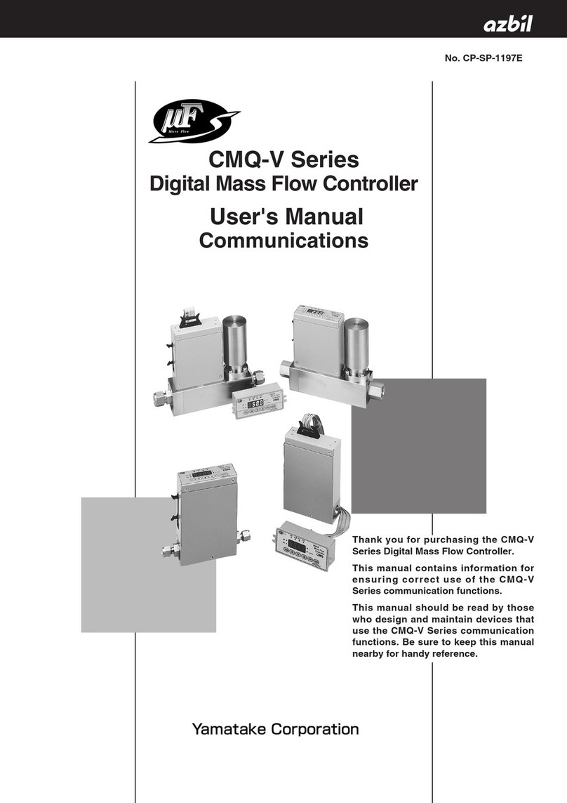
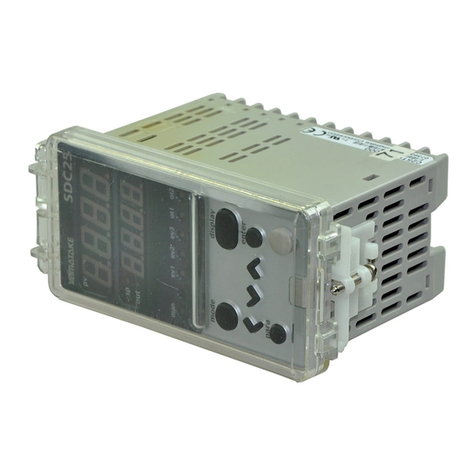
Yamatake Neostat T6065 Series User manual

AB-5881
1
Neostat
Room Temperature Controller T6065, T9065
Room Humidity Controller H615, H915
Specifications
Temperature Controllers
Model Control
Provided Range Summer-winter
changeover switch
T6065A2026 No
T6065B2024 Two-position Yes
T9065A2020 No
T9065B2028 Proportional
15 to 30 °C
Yes
Humidity Controllers
Model Control Provided Range
H615A2036 30 to 80 % RH
H615B2044 Two-position 50 to 90 % RH
H915A2022 Proportional 30 to 80 % RH
Electrical rating:
T6065A, B
125 V AC 250 V AC
Full load 6 A 3 A
Locked rotor 36 A 18 A
H615A
Dehumidification Humidification
125 V AC 250 V AC 125 V AC 250 V AC
Full load 3.0 A 1.5 A 4.4 A 2.2 A
Locked rotor 18.0 A 9.0 A 26.4 A 13.2 A
Resistive load ――
8.0 A 4.0 A
Item Specifications
Rated operat-
ing conditions
15 to 40 °C (95 % RH or less)
Transport/
storage
conditions
–20 to 50 °C (95 % RH or less)
Differenitial T6065A,B : Approx. 1 °C fixed
H615A : Approx. 5 % RH fixed
(H615A2036 : at 50 % RH,
H615A2044 : at 65 % RH)
Throttling range T9065A,B : Approx. 2 °C fixed
H915A : Approx. 12 % RH fixed
(at 50 % RH)
Element Temperature controller : Diaphragm
Humidity controller : Nylon ribbon
Item Specifications
Cover Pale beige (equivalent to Munsell 5Y8/1)
Base Dark gray (equivalent to Munsell N3.0)
Attachment ●Terminal block: 1
●Mounting screw between body and termi-
nal block (M3x8): 1
●Tapping screw for mounting terminal block
(M2.6x8): 2
Auxiliary
(order sepa-
rately)
Base plate
Q6065A1007....... T6065A
Q6065B1005....... T6065B
Q9065A1001....... T9065A
Q9065B1009....... T9065B
Q6150A1003....... H615A
Q9150A1007....... H915A
Thermo plate for individual room control
QY11A01J1
Thermo plate
DY2000A1003 (One unit, horizontal
mounting)
DY2000A1002 (One unit, vertical mount-
ing)
DY2000A2003 (Two unit, horizontal
mounting)
DY2000A2002 (Two unit, vertical mount-
ing)
Multi-thermo case
TY110A
Specifications/Instructions
With baseplate and mounting plate model

2 AB-5881
Fig.1 Dimensions in mm.-with baseplate and mounting plate
model
Fig.2 Dimensions in mm.-without baseplate and mounting
plate model
Installation
Location
1. Locate the Neostat about 1.5 m (5 ft.) above the floor
where average temperature and humidity of the space
can be measured.
2. Avoid “dead spots” such as behind large pieces of
furniture or doors without good air circulation.
3. Do not mount the Neostat where it may be affected by
drafts, hot or cold air from ducts, radiant heat from the
sun or appliances.
4. Do not mount the Neostat where it may be affected by
vibration.
5. Do not mount the humidity controller where it may be
affected by water drop. Do not allow dew
condensation to form on the unit.
Safety Instructions
Please read these instructions carefully and use the product properly. Please keep these instructions on hand for refer-
ence at any time.
Usage Restrictions
This product is targeted for general air conditioning. Do not use this product in a situation where human life may be
affected. If this product is used in clean rooms or places where reliability or control accuracy is particularly required,
please contact Yamatake’s sales representatives. Yamatake Building Systems Co., Ltd. bears no responsibility for
any benefit, or lack of benefit, derived from the operation by the customer.
CAUTION
●Disconnect the power supply before beginning wiring to prevent electrical shock.
CAUTION
●Installer must be a trained, experienced service technician.
●Check the ratings given in this instruction to prevent equipment damage.
●Check the environment given in this instruction to prevent equipment damage.
●All wiring must conform to local codes and ordinances.
●Use crimp contacts with insulation jackets for wire terminals.
●Do not dissolve this product except for removing the cover during wiring or part replacement to prevent
equipment damage.
M3 Tapped-Hole (2)
4.4 DIA
Mountin
g
Hole
72
90
90 71
27 1 8
66.7
86
9.7
86
43
5
5
72
71
39 15
Thermo plate (Order Separately)
Mounting hole

3 AB-5881
Mounting Procedure of Baseplate (See Fig. 3)
1. Install box cover with pitch of 66.7 mm (Box cover JIS
C 8339) on the outlet box when needed.
2. Put mounting plate (order separately) on the box
cover.
3. Then put baseplate (order separately) on the
mounting plate.
4. Wire the baseplate. Refer to wiring section.
5. Remove the cover. (See Fig. 5) Then, mount the
Neostat on the baseplate. See Fig. 6 also.
6. Replace the cover.
Fig.3 Mounting baseplate
Mounting Procedure of Thermo plate (See Fig. 4)
1. Mount the Thermo plate. Refer to the instruction of
Thermo plate.
2. Mount the terminal block on the baseplate.
3. Wire the terminal block. Refer to wiring section.
4. Remove the cover. (See Fig. 5) Then, put the Neostat
on the baseplate (See Fig. 6) and mount to the
terminal block.
5. Replace the cover.
Fig.4 Mounting thermo plate
Cover
Neostat mounting screw
M3, L=8
Terminal block mounting screw
M2.6×8, Tapping screw (2)
Neostat
Terminal block
Baseplate
mounting screw
Baseplate
Mounting plate
Mounting screw
Mounting
Plate
Box cover
Thermo plate (Order separately-
Figure shows QY10A01J1)
Order separately
(
base
p
late
)
Cover
Mounting screw for body
M3, L=8
Mounting screw for base plate
M3, L=3 (2)
Neostat
Base plate
Knock out
for surface
wirin
g
Mounting screw
M3, L=8 (2)
Mounting plate
Box cover
(JIS C 8339)
Pitch of
66.7 mm

4 AB-5881
Fig. 5 Attach/detach cover Fig. 6 Install Neostat
Wiring
All wiring must comply with local electrical codes and
ordinance. In general these codes require:
1. Wire no smaller than #14 (1.6 mm).
2. All terminal connections should be carefully made. In
making surface wiring, use knockout on the top of the
body where marked.
3. Make correct wiring. Check the screw terminals for
loose connections.
Fig.7 Connection diagram
Setting
1. Remove the cover.
2. T6065B and T9065B have S/W changeover switch.
Set the lever in the specified position. See Fig. 10.
Note: When the equipment is energized, do not
change the switch.
3. The temperature controller have setpoint stoppers
(Fig. 8) and the humidity controller have a setpoint
lock screw (Fig. 9). The Neostat is shipped from the
factory with setpoint dial locked in the position as
follows:
Temperature controller→30 °C
Humidity controller 30 to 80 % RH model→80 % RH
50 to 90 % RH model→90 % RH
After sliding the stoppers of the temperature controller
or after loosening the lock screw of the humidity
controler, adjust the setpoint dial to the desired
temperature or humidity. Setpoint is the center of
throttling range for proportional controllers. For two-
position controllers, see Figs. 11 and 12.
4. Set the setpoint stoppers or a lock screw as occasion
calls.
5. Replace the cover.
Push spring plate
for opening
Cover
Neostat
Baseplate
T9065B
R
W
RB
W
B
S/W changeover SWS/W changeover SW
T6065B
R
W
RB
(Summer)
B
H615A
R
Humidifi-
cation
Dehumidi-
fication
B
W
T6065A
Rise
R
Cooling
Heating
W
B
H915A
R
B
W
T9065A
R
W
B
Rise Rise Rise
RiseRise
(Winter)
SW
(Summer) (Winter)
SW
Clutch, push down and
fasten using the
Neostat mounting
screw shown in the
Fig.3 and Fig4.
Back of Neostat
Baseplate

5 AB-5881
Fig. 8 Temperature controller Fig. 9 Humidity controller
Fig. 10 Summer-Winter changeover switch
of T6065B, T9065B
Fig. 11 H615A Switching action
Fig.12 T6065A, B Switching action
Setpoint dial
Upper stopper
The setpoint stoppers can be
moved in the direction of the
arrows by lightly pressing inward.
To fix the setpoint, set the
setpoint dial to the desired
temperature and place the both
stoppers in the central position.
Set
p
oint dial
Setpoint lock screw
By tightening the lock screw, the setpoint can be
fixed.
- Undo the setpoint lock
Turn the lock screw about two turns counter-
clockwise.
- Lock the setpoint
Set the setpoint dial to the desired temperature
and turn the lock screw about two turns clockwise.
Note: When the equipment is
energized, do not move
S/W changeover
switch.
Summer-winter
changeover switch
Summer-winter
indication
S: Summer
W: Winter
Makes R-B
Humidity rise
Makes R-W
Differential
Setpoint
T6065A : Makes R-B
T6065B : Makes R-B (change over SW. in
Winter position)
Makes: R-B (change over SW. in
Summer position) Temperature
rise
T6065A : Makes R-W
T6065B : Makes R-B (change over SW. in
Winter position)
Breaks: R-B (change over SW. in
Summer position)
Setpoint
Differential

6 AB-5881
Building Systems Company
International Business Headquarters
Totate International Building
1-12-19, Shibuya
Shibuya-Ku,Tokyo, 150-8316
URL:http//www.yamatake.com
First Printing Dec. 2000 Printed in Japan. AB-5881 3H-H (W)
Specifications are subject to change without notice.
This manual suits for next models
10
Table of contents
Other Yamatake Controllers manuals