manuals.online logo
Brands
  1. Home
  2. •
  3. Brands
  4. •
  5. YASKAWA
  6. •
  7. DC Drive
  8. •
  9. YASKAWA V1000 SI-S3/V User manual

YASKAWA V1000 SI-S3/V User manual

MANUAL NO. SIEP C730600 24A
Technical Manual
CANopen
Type SI-S3/V
YASKAWA AC Drive-V1000 Option
To properly use the product, read this manual thoroughly and retain
for easy reference, inspection, and maintenance. Ensure the end user
receives this manual.
YASKAWA ELECTRIC SIEP C730600 24A V1000 Option CANopen Technical Manual 3
Table of Contents
1 Preface and Safety. . . . . . . . . . . . . . . . . . . . . . . . . . . . . . . . . . . . . . . . . . . . . . . . . . . . . . . . . . . . . . . . . . . . . 4
2 Product Overview . . . . . . . . . . . . . . . . . . . . . . . . . . . . . . . . . . . . . . . . . . . . . . . . . . . . . . . . . . . . . . . . . . . . . 7
3 Receiving . . . . . . . . . . . . . . . . . . . . . . . . . . . . . . . . . . . . . . . . . . . . . . . . . . . . . . . . . . . . . . . . . . . . . . . . . . . . 8
4 CANopen Option Components. . . . . . . . . . . . . . . . . . . . . . . . . . . . . . . . . . . . . . . . . . . . . . . . . . . . . . . . . . . 9
5 Installation Procedure. . . . . . . . . . . . . . . . . . . . . . . . . . . . . . . . . . . . . . . . . . . . . . . . . . . . . . . . . . . . . . . . . 11
6 CANopen Option Drive Parameters . . . . . . . . . . . . . . . . . . . . . . . . . . . . . . . . . . . . . . . . . . . . . . . . . . . . . . 15
7 Communication Objects Overview . . . . . . . . . . . . . . . . . . . . . . . . . . . . . . . . . . . . . . . . . . . . . . . . . . . . . . 16
8 Object Description. . . . . . . . . . . . . . . . . . . . . . . . . . . . . . . . . . . . . . . . . . . . . . . . . . . . . . . . . . . . . . . . . . . . 18
9 Fault Diagnosis and Possible Solutions . . . . . . . . . . . . . . . . . . . . . . . . . . . . . . . . . . . . . . . . . . . . . . . . . . 25
10 MEMOBUS/Modbus Data Table . . . . . . . . . . . . . . . . . . . . . . . . . . . . . . . . . . . . . . . . . . . . . . . . . . . . . . . . 27
11 Specifications . . . . . . . . . . . . . . . . . . . . . . . . . . . . . . . . . . . . . . . . . . . . . . . . . . . . . . . . . . . . . . . . . . . . . . 34
Copyright © 2007 YASKAWA ELECTRIC CORPORATION
All rights reserved. No part of this publication may be reproduced, stored in a retrieval system, or transmitted, in any form or by any
means, mechanical, electronic, photocopying, recording, or otherwise, without the prior written permission of Yaskawa. No patent
liability is assumed with respect to the use of the information contained herein. Moreover, because Yaskawa is constantly striving to
improve its high-quality products, the information contained in this manual is subject to change without notice. Every precaution has
been taken in the preparation of this manual. Yaskawa assumes no responsibility for errors or omissions. Neither is any liability
assumed for damages resulting from the use of the information contained in this publication.
4YASKAWA ELECTRIC SIEP C730600 24A V1000 Option CANopen Technical Manual
1 Preface and Safety
Yaskawa manufactures products used as components in a wide variety of industrial systems and equipment. The selection and application of
Yaskawa products remain the responsibility of the equipment manufacturer or end user. Yaskawa accepts no responsibility for the way its products
are incorporated into the final system design. Under no circumstances should any Yaskawa product be incorporated into any product or design as the
exclusive or sole safety control. Without exception, all controls should be designed to detect faults dynamically and fail safely under all
circumstances. All systems or equipment designed to incorporate a product manufactured by Yaskawa must be supplied to the end user with
appropriate warnings and instructions as to the safe use and operation of that part. Any warnings provided by Yaskawa must be promptly provided
to the end user. Yaskawa offers an express warranty only as to the quality of its products in conforming to standards and specifications published in
the Yaskawa manual. NO OTHER WARRANTY, EXPRESS OR IMPLIED, IS OFFERED. Yaskawa assumes no liability for any personal injury,
property damage, losses, or claims arising from misapplication of its products.
1 Preface and Safety
YASKAWA ELECTRIC SIEP C730600 24A V1000 Option CANopen Technical Manual 5
◆Applicable Documentation
The following manuals are available for SI-S3/V CANopen Option unit:
For the drive setup, refer to one of the documentation listed below.
◆Terms
Note: Indicates a supplement or precaution that does not cause drive damage.
◆Registered Trademarks
• CANopen is a registered trademark of the CAN in Automation (CiA).
• Other company names and product names listed in this manual are registered trademarks of those companies.
◆Supplemental Safety Information
Read and understand this manual before installing, operating, or servicing this option unit. The option unit must be installed according to this
manual and local codes.
The following conventions are used to indicate safety messages in this manual. Failure to heed these messages could result in serious or possibly
even fatal injury or damage to the products or to related equipment and systems.
Option Unit
V1000 Option CANopen Installation Manual
Manual No. : TOBP C730600 24
Read this manual first.
The installation manual is packaged with the CANopen Option and contains a basic overview of wiring, settings, functions, and
fault diagnoses.
V1000 Option CANopen Technical Manual (this book)
Manual No. : SIEP C730600 24
The technical manual contains detailed information and command registers.
To obtain the technical manual access these sites:
Europe: http://www.yaskawa.eu.com
Japan: https://www.e-mechatronics.com
Other areas: contact a Yaskawa representative.
Yaskawa Drive
V1000 Series AC Drive Technical Manual
Manual No. : SIEP C710606 16
This manual describes installation, wiring, operation procedures, functions, troubleshooting, maintenance, and inspections to perform before operation.
To obtain instruction manuals for Yaskawa products access these sites:
Europe: http//www.yaskawa.eu.com
Japan: https//www.e-mechatronics.com
Other areas: contact a Yaskawa representative
V1000 Series AC Drive Quick Start Guide
This guide is packaged together with the product. It contains basic information required to install and wire the drive. This guide provides basic
programming and simple set-up and adjustment.
Drive: Yaskawa AC Drive -V1000 Series
CANopen Option: Yaskawa AC Drive -SI-S3/V CANopen option unit for the Yaskawa V1000 drive
DANGER
Indicates a hazardous situation, which, if not avoided, will result in death or serious injury.
WARNING
Indicates a hazardous situation, which, if not avoided, could result in death or serious injury.
CAUTION
Indicates a hazardous situation, which, if not avoided, could result in minor or moderate injury.
NOTICE
Indicates an equipment damage message.
STOP
(Hz)
(Hz)
(A)
(V)










V1000
๟ᵄᢙᜰ઎
ᱜォㅒォㆬᛯ
಴ജ๟ᵄᢙ
಴ജ㔚ᵹ
಴ജ㔚࿶
ࡕ࠾࠲
ࡌ࡝ࡈࠔࠗ
࠮࠶࠻ࠕ࠶ࡊ
ࡄ࡜ࡔ࡯࠲⸳ቯ
ࠝ࡯࠻࠴ࡘ࡯࠾ࡦࠣ
ᝪ߃ઃߌޔㆇォߩ೨ߦߪᔅߕขᛒ⺑᣿ᦠࠍ⺒߻ߎߣޕ
ㅢ㔚߅ࠃ߮㔚Ḯㆤᢿᓟ
5
ಽએౝߪࡈࡠࡦ࠻ࠞࡃ࡯ࠍ
ᄖߐߥ޿ߎߣޕ
400V
⚖ࠗࡦࡃ࡯࠲ߩ႐วߪޔ㔚Ḯߩᕈὐ߇ធ࿾
ߐࠇߡ޿ࠆߎߣࠍ⏕⹺ߔࠆߎߣޕ㧔ޓޓኻᔕ㧕
ߌ߇㧚ᗵ㔚ߩ߅ߘࠇ߇޽ࠅ߹ߔޕ
ෂޓ㒾
1 Preface and Safety
6 YASKAWA ELECTRIC SIEP C730600 24A V1000 Option CANopen Technical Manual
■General Safety
■Option Unit Label Warnings
Warning information is displayed on the option unit as shown in the figure below. Follow all warnings and safety instructions when using the
product.
When using the drive in an area that may require displaying warning information in Japanese or Chinese, a sticker is provided with the CANopen
Option. This sticker can be placed over the English and French warnings on the front of the CANopen Option.
■Warning Contents
General Precautions
• The diagrams in this section may include option units and drives without covers or safety shields to illustrate details. Be sure to reinstall covers or
shields before operating any devices. The option board should be used according to the instructions described in this manual.
• Any illustrations, photographs, or examples used in this manual are provided as examples only and may not apply to all products to which this
manual is applicable.
• The products and specifications described in this manual or the content and presentation of the manual may be changed without notice to improve
the product and/or the manual.
• When ordering a new copy of the manual due to damage or loss, contact your Yaskawa representative or the nearest Yaskawa sales office and
provide the manual number shown on the front cover.
DANGER
Heed the safety messages in this manual.
Failure to comply will result in death or serious injury.
The operating company is responsible for any injuries or equipment damage resulting from failure to heed the warnings in this
manual.
NOTICE
Do not expose the drive to halogen group disinfectants.
Failure to comply may cause damage to the electrical components in the option unit.
Do not pack the drive in wooden materials that have been fumigated or sterilized.
Do not sterilize the entire package after the product is packed.
V1000
Warning
information
AVERTISSEMENT
Lire le manuel avant l'installation.
Attendre 5 minutes apres la coupure de l'alimentation,
pour permettre la decharge des condensateurs.
Pour repondre aux exigences , s assurer que le
neutre soit relie a la terre, pour la serie 400V.
WARNING
Read manual before installing.
Wait 5 minutes for capacitor discharge after
disconnecting power supply.
To conform to ޓrequirements, make sure
to ground the supply neutral for 400V class.
Risk of electric shock.
Risque de decharge
electrique.
2 Product Overview
YASKAWA ELECTRIC SIEP C730600 24A V1000 Option CANopen Technical Manual 7
2 Product Overview
◆About This Product
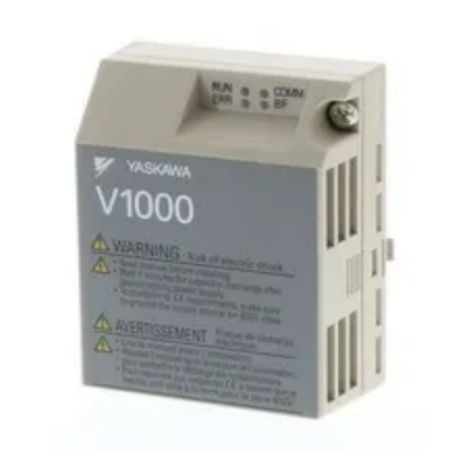
The SI-S3/V is an option unit designed to connect the V1000 drive to a CANopen network. Using this option unit a CANopen master can
• Operate the drive
• Monitor the drive operation status
• Read or modify drive parameters
The SI-S3/V supports the following communication profiles
• DS 301 Ver. 4.02
• DSP 402 Ver. 1.1 Velocity Mode
◆Applicable Models
The CANopen Option can be used with the drive models in Table 1 .
Table 1 Applicable Models
<1> See “PRG” on the drive nameplate for the software version number.
Drive Software Version <1>
CIMR-VABA5010, 1010 or later
CIMR-VAFA5010, 1010 or later
CIMR-VAJA5010, 1010 or later
8YASKAWA ELECTRIC SIEP C730600 24A V1000 Option CANopen Technical Manual
3 Receiving
3 Receiving
Please perform the following tasks after receiving the CANopen Option:
• Inspect the CANopen Option for damage.
If the CANopen Option appears damaged upon receipt, contact the shipper immediately.
• Verify receipt of the correct model by checking the information on the PCB (see Figure 1).
• If you have received the wrong model or the CANopen Option does not function properly, contact your supplier.
◆Contents and Packaging
Table 2 Contents of Package
◆Tool Requirements
A Phillips screwdriver (for screw size <1> #1 or #2, U.S. standard size) is required to install the CANopen Option.
<1> Screw sizes vary by drive capacity. Select a screwdriver that matches the drive capacity.
Note: Tools required to prepare CANopen cables for wiring are not listed in this manual.
Description: Option Unit Ground Cables Warning Labels Installation Manual
_
Quantity: 1411
MANUAL
4 CANopen Option Components
YASKAWA ELECTRIC SIEP C730600 24A V1000 Option CANopen Technical Manual 9
4 CANopen Option Components
◆CANopen Option
Figure 2
Figure 1 Option Unit
<1> Cables are not connected to the CANopen Option and are packaged separately in the box.
◆Dimensions
The installed CANopen Option adds 27 mm (1.06 in.) to the total depth of the drive.
Figure 3
Figure 2 Dimensions
Figure 1
A – LED (RUN: green) G – Function Earth cable connection (FE)
B – LED (ERR: red) H – Mounting clip
C – Option cover I – Cable <1>
D – CANopen PCB J – Through-hole for cable
E – Attachment screw hole for option
cover
K – Communication cable connector
(9 pin D-SUB)
F – PCB part number L – Option board connector
A
B
C
CANopen with cover attached
L
H
E
D
H
G
I
J
CANopen with cover removed
underside
K
F
FE
27 mm (1.06 in.)
4 CANopen Option Components
10 YASKAWA ELECTRIC SIEP C730600 24A V1000 Option CANopen Technical Manual
◆Communication connector
The SI-S3/V is connected to the network using a 9 pin D-SUB connector. The connector location is illustrated in Figure 3, the pin assignment is
explained in Table 3.
Figure 4
Figure 3 Communication connector location
Table 3 Communication connector (9 pin D-SUB)
◆CANopen Option LED Display
The SI-S3/V has two LEDs that indicate the Option unit or communication status. The indications are conform with the DS303, Part 3: Indicator
Specification.
■Checking LED Operation
Table 4 LED Display
Figure 4 explains the indicator flash rates.
Figure 4 LED Flash Rates and Meaning
◆Setting Node Address
Set the node address in the drive parameter F6-35. The node address can be set between 1 and 127 but has to be unique in the network. If the Node
address is set to 0, communications will not be possible and the ERR LED will flash.
CANopen Connector Pin Signal Description
1––
2 CAN_L CAN_L bus line (dominant low)
3 CAN_GND CAN Ground
4––
5 CAN_SHLD CAN shield
6––
7 CAN_H CAN_H bus line (dominant high)
8––
9––
– CAN_SHLD CAN shield
LED Color Display Meaning
RUN Green
On Operational State
Blinking Pre-operational State
Single flash Stopped
ERR Red
On Bus off
Blinking Bus initialization failed (parameter setting error)
Single flash Fault has occurred
Receiving CAN error frame (too many error frames)
Double flash Guard / Heartbeat event has occurred
Off Online
1
5
6
9
Bottom View
7
8
2
3
4
Blinking
ON
1s 2s
ON
ON
ON
ON
ERR
RUN
ERR
RUN
Single flash
ERR
Double flash
5 Installation Procedure
YASKAWA ELECTRIC SIEP C730600 24A V1000 Option CANopen Technical Manual 11
5 Installation Procedure
◆Section Safety
DANGER
Electrical Shock Hazard
Do not connect or disconnect wiring while the power is on.
Failure to comply will result in death or serious injury.
Disconnect all power to the drive, wait at least five minutes after all indicators are off, measure the DC bus voltage to confirm safe
level, and check for unsafe voltages before servicing to prevent electric shock. The internal capacitor remains charged even after the
power supply is turned off. The charge indicator LED will extinguish when the DC bus voltage is below 50 Vdc.
WARNING
Electrical Shock Hazard
Do not remove option board cover while the power is on.
Failure to comply could result in death or serious injury.
The diagrams in this section may include option units and drives without covers or safety shields to show details. Be sure to reinstall
covers or shields before operating any devices. The option board should be used according to the instructions described in this
manual.
Do not allow unqualified personnel to use equipment.
Failure to comply could result in death or serious injury.
Maintenance, inspection, and replacement of parts must be performed only by authorized personnel familiar with installation,
adjustment, and maintenance of this product.
Do not use damaged wires, place excessive stress on wiring, or damage the wire insulation.
Failure to comply could result in death or serious injury.
Fire Hazard
Tighten all terminal screws to the specified tightening torque.
Loose electrical connections could result in death or serious injury by fire due to overheating of electrical connections.
NOTICE
Damage to Equipment
Observe proper electrostatic discharge procedures (ESD) when handling the option unit, drive, and circuit boards.
Failure to comply may result in ESD damage to circuitry.
Never shut the power off while the drive is outputting voltage.
Failure to comply may cause the application to operate incorrectly or damage the drive.
Do not operate damaged equipment.
Failure to comply may cause further damage to the equipment.
Do not connect or operate any equipment with visible damage or missing parts.
Do not use unshielded cable for control wiring.
Failure to comply may cause electrical interference resulting in poor system performance.
Use shielded twisted-pair wires and ground the shield to the ground terminal of the drive.
Properly connect all pins and connectors.
Failure to comply may prevent proper operation and possibly damage equipment.
Check wiring to ensure that all connections are correct after installing the option unit and connecting any other devices.
Failure to comply may result in damage to the option unit.
5 Installation Procedure
12 YASKAWA ELECTRIC SIEP C730600 24A V1000 Option CANopen Technical Manual
◆Prior to Installing the Option Unit
Prior to installing the CANopen Option, wire the drive and make necessary connections to the drive terminals. Refer to the V1000 Quick Start
Guide for information on wiring and connecting the drive. Verify that the drive runs normally without the option installed.
◆Installing the CANopen Option
Remove the front cover of the drive before installing the CANopen Option. Wire the drive terminals first, as they are obscured by the CANopen
Option. Follow the directions below for proper installation.
Note: Run the drive before installing the CANopen Option to ensure that the drive or drive connections are not faulty.
1. Switch off the power supply to the drive.
DANGER! Electrical Shock Hazard - Do not connect or disconnect wiring while the power is on. Failure to comply will result in death or serious injury. Before installing the
CANopen Option, disconnect all power to the drive. The internal capacitor remains charged even after the power supply is turned off. The charge indicator LED will
extinguish when the DC bus voltage is below 50 Vdc. To prevent electric shock, wait at least five minutes after all indicators are off and measure the DC bus voltage level to
confirm safe level.
2. Remove the front cover. The original drive front cover may be discarded because it will be replaced by the CANopen Option cover in step 7.
Figure 5
Figure 5 Remove Front Cover
3. Remove the bottom cover and connect the CANopen Option ground cable to the ground terminal.
Figure 6
Figure 6 Connect Ground Cable
Note: The four different ground cables packaged with the CANopen Option connect the unit to different models. Select the proper ground cable from the CANopen Option kit
depending on drive size.
Figure 7
Figure 7 Ground Cable
Note: 1. The four different ground cables packaged with the CANopen Option connect to different models. Select the proper ground cable from the CANopen Option kit depending on
drive size.
2. Cover removal for certain larger models with a Terminal Cover:
-Single-Phase 200 V Class: CIMR-VBA0006 to BA0018
-Three-Phase 200 V Class: CIMR-V2A0008 to 2A0069
-Three-Phase 400 V Class: All models
Remove the terminal cover before removing the bottom cover to install the CANopen Option ground cable. Replace the terminal cover after wiring the CANopen Option
ground cable.
Figure 8
Figure 8 Models with Terminal Cover
4. Reattach the bottom cover.
A – Option unit connection: screw size = M3
B – Drive-side connection: screw size = M3.5 to M6
ground terminal
ground cable
bottom cover
A
B
5 Installation Procedure
YASKAWA ELECTRIC SIEP C730600 24A V1000 Option CANopen Technical Manual 13
5. Connect the CANopen Option to the drive. Properly secure the tabs on the left and right sides of the CANopen Option to the drive case.
Figure 9
Figure 9 Attach CANopen Option
6. Connect the ground cable from the drive ground terminal to the CANopen Option ground. When wiring the CANopen Option, pass the ground cable
through the inside of the drive bottom cover, then pass the ground cable into the through-hole at the front of the CANopen Option.
Figure 10
Figure 10 Ground Cable Connection
7. Attach the CANopen Option cover to the front of the CANopen Option.
Figure 11
Figure 11 Attach Cover
Note: When using the drive in an area that may require displaying warning information in Japanese or Chinese, a sticker has been provided with the CANopen Option. This
sticker can be placed over the English and French warnings on the front of the CANopen Option.
◆Communication Cable Specifications
Use a CANopen-dedicated communication cable only; To ensure proper performance Yaskawa recommends using CANopen dedicated
communication cables only.
◆Wiring the CANopen Option
The CANopen option must be connected to the network using a 9 pin D-SUB connector like shown in Figure 12.
Figure 12
Figure 13
Figure 12 Wiring Diagram
<1> The FE terminal on the CANopen Option must be connected to the drive ground terminal using one of the 4 delivered ground wires.
tabs should line up
tabs should line up
ground
cable
drive ground
terminal
Pass the ground
cable through
the bottom cover
of the drive.
through-hole
for ground cable
ground cable
tabs should line up
V1000
D-SUB Connector
SI-S3/V
CAN_SHLD
CAN_L
CAN_H7
2
3
CANopen Cable Connector
CN5
FE
(Shell)
<1>
CANopen Cable
5 Installation Procedure
14 YASKAWA ELECTRIC SIEP C730600 24A V1000 Option CANopen Technical Manual
◆Termination
Both ends of a CANopen bus system have to be terminated with a 120 Ωresistor. As the SI-S3/V has no build in terminating resistor, make sure to
apply a terminating resistor as shown in Figure 13 if the SI-S3/V is the last node in the network.
Figure 13 Terminating Diagram
<1> The FE terminal on the CANopen Option must be connected to the drive ground terminal using one of the 4 delivered ground wires.
◆EDS Files
For easy network implementation of drives equipped with a SI-S3/V, an EDS file can be obtained from:
Europe: http://www.yaskawa.eu.com
Japan: https://www.e-mechatronics.com
Other areas: contact a Yaskawa representative
V1000
D-SUB Connector
SI-S3/V
CAN_SHLD
CAN_L
CAN_H
7
2
3
CANopen Cable Connector
CN5
FE
(Shell)
<1>
CANopen Cable
120 Ω
For the last node on the network,
apply a terminating resister.
6 CANopen Option Drive Parameters
YASKAWA ELECTRIC SIEP C730600 24A V1000 Option CANopen Technical Manual 15
6 CANopen Option Drive Parameters
Confirm the proper setting of all parameters in Table 5 before starting network communications.
Table 5 Parameter Settings
<1> To start and stop the drive from a CANopen master device using serial communications, set b1-02 to 3. To control the frequency reference of the drive via the master device, set b1-01 to
"3".
<2> When b1-01=3 and/or b1-02=3 are selected and the communication option is not installed, V1000 detects oPE07 instead of oPE05 with software version 1010.
<3> E2-04, E4-04 and E5-04 are necessary to set up when the Drive Profile DSP402 objects are used.
<4> Default setting value is dependent on parameter E5-01, Motor Code Selection.
<5> If F6-03 is set to 3, then the drive will continue to operate when an EF0 fault is detected. Take proper safety measures, such as installing an emergency stop switch.
<6> All node addresses must be unique. The ERR LED will illuminate when 0 or greater than 127 is entered.
<7> Default setting is 99 for software versions 5010, 1010, and 1011, 0 for software version 1012 or later.
<8> The setting of o1-03 affects the data format in Object 2200 (Hex.) (Motor Speed)
No. Name Description Default
b1-01
<1> <2> Frequency Reference Selection
Selects the frequency reference input source
0: Operator - Digital preset speed d1-01 to d1-17
1: Terminals - Analog input terminal A1 or A2
2: MEMOBUS/Modbus communications
3: Option PCB
4: Pulse Input (Terminal RP)
1
b1-02
<1> <2> Run Command Selection
Selects the run command input source
0: Digital Operator - RUN and STOP keys
1: Digital input terminals S1 to S7
2: MEMOBUS/Modbus communications
3: Option PCB
1
E2-04 <3> Motor 1 Motor Poles Set the number of motor poles described on the motor nameplate. 4 poles
E4-04 <3> Motor 2 Motor Poles Sets the number of poles of motor 2. 4 poles
E5-04 <3> PM Motor Pole Number Sets the number of motor poles for PM motors. <4>
F6-01 Operation Selection after Communications Error
Determines drive response when a bUS error is detected during communications with the
CANopen Option
0: Ramp to Stop
1: Coast to Stop
2: Fast-Stop
3: Alarm Only
1
F6-02 External Fault Detection Conditions (EF0)
Sets the condition for external fault detection (EF0)
0: Always detected
1: Detected only during operation
0
F6-03 Stopping Method for External Fault from
Communication Option Board
Determines drive response for external fault input (EF0) detection during CANopen
communication
0: Ramp to Stop
1: Coast to Stop
2: Fast-Stop
3: Alarm Only <5>
1
F6-04 bUS Error Detection Delay Time Set the maximum time the drive should wait for a communication error to occur (bUS)
Range 0.00 to 5.00 s 0.05
F6-35 <6> Node Address 0 to 127 <7>
F6-36 Communication Speed
0: Disabled
1: 10 kbps
2: 20 kbps
3: 50 kbps
4: 125 kbps
5: 250 kbps
6: 500 kbps
7: 800 kbps
8: 1 Mbps
6
o1-03 <8> Digital Operator Display Selection
Sets the units to display the frequency reference and output frequency.
0: Hz
1: % (100% = E1-04)
2: min-1 (enter the number of motor poles into E2-04/E4-04/E5-04)
3: User defined by parameters o1-10 and o1-11
0
16 YASKAWA ELECTRIC SIEP C730600 24A V1000 Option CANopen Technical Manual
7 Communication Objects Overview
The Object Dictionary is essentially a group of objects accessible via the network in an ordered pre-defined fashion. Each object uses a 16 bit index.
The Object Dictionary consists of three sections:
• Communications Profile (index numbers 1000 - 1FFF) contains objects related to the CANopen network, which are shared with each device.
• Manufacturer Profile (index numbers 2000 - 5FFF) concerns objects that have been set for manufacturer-specific functions. These objects are
specific to Yaskawa products, and therefore are not compatible with other productsthat may be CANopen.
• Drive and Motion Profile (index numbers 6000 - 9FFF) includes data objects shared among all device classes that can read and write across the
network. SI-S3/V is compatible with DSP 402 Drive and Motion Control Profile and Velocity Mode.
◆Communication Objects (DS 301)
◆Manufacturer Specific Objects (DS 301)
■Input Objects
■Output Objects
Index (Hex.) Name Page
1000 Device Type 18
1001 Error Register 18
1003 Pre-defined Error Field 18
1005 COB-ID SYNC Message 18
1008 Manufacturer Device Name 18
1009 Manufacturer Hardware Version 18
100A Manufacturer Software Version 18
100C Guard Time 18
100D Life Time Factor 18
100E Node Guarding Identifier 18
1010 Store Parameters 19
1011 Restore Default Parameters 19
1014 COB-ID Emergency Object 19
1016 Consumer Heartbeat Time 19
1017 Producer Heartbeat Time 19
1018 Identity Object 19
Index (Hex.) Name Page
2000 Operation Command 19
2010 Speed Command 19
2020 Torque Limit 19
2030 Torque Compensation 20
2040 MEMOBUS Read Command 20
2050 MEMOBUS Write Command 20
2060 MEMOBUS Not Limited Enter Command 20
2070 MEMOBUS Limited Enter Command 20
Index (Hex.) Name Page
2100 Drive Status 20
2110 Output Frequency 21
2120 Output Current 21
2130 Output Torque 21
2140 MEMOBUS Read Command Response 21
2150 MEMOBUS Write Command Response 21
2160 MEMOBUS Not Limited Enter Command Response 21
2200 Motor Speed 21
7 Communication Objects Overview
YASKAWA ELECTRIC SIEP C730600 24A V1000 Option CANopen Technical Manual 17
◆Drives and Motion Profile (DSP 402)
The drive supports the Drive and Motion Profile DSP 402 Velocity Mode. Before using the Velocity Mode objects the following parameters have to
be set up in the drive:
• The motor pole number must be set up in E2-04 for motor 1, E4-04 for motor 2 and E5-04 for PM motors.
• The frequency reference and output frequency display unit has to be set to min-1 by setting parameter o1-03 = 2.
If these settings are not done properly, the Velocity Mode objects can not be used or deliver wrong data.
■Common Entries
<1> YASKAWA specifies this object as the drive digital output monitor. (Input of the network)
<2> YASKAWA specifies this object as additional digital inputs of the drive. (Output of the network)
■Device Control
■Velocity Mode
Index (Hex.) Name Page
60FD Digital Input <1> 21
60FE Digital Output <2> 21
Index (Hex.) Name Page
6040 Controlword 22
6041 Statusword 22
6061 Modes_of_operation_display 22
Index (Hex.) Name Page
6042 vl_target_velocity 22
6043 vl_velocity_demand 22
6044 vl_control_effort 22
6046 vl_velocity_min_max_amount 22
6048 vl_velocity_acceleration 22
6049 vl_velocity_deceleration 22
604A vl_velocity_quick_stop 23
604C vl_dimension_factor 23
604D vl_pole_number 23
18 YASKAWA ELECTRIC SIEP C730600 24A V1000 Option CANopen Technical Manual
8 Object Description
◆Communication Objects (DS 301)
■Device Type
This object describes the type of the device and its functionality. It is composed of a 16 bit field which describes the device profile that is used and a
second 16 bit field which gives additional information about optional functionality.
■Error Register
This register shows the fault status of the device. If any errors occurs in the device bit 0 (generic error) is set to one.
■Pre-defined Error Field
This register provides a history of errors that occurred in the drive and have been signalized via the Emergency object. Subindex 0 contains the
number of errors. Subindexes 1 to FF contains a rolling list of error codes where subindex 1 always contains the last occurred error. Refer to Drive
Error List on page 23 for a list of possible error codes.
Writing a 0 into subindex 0 resets the error field.
■COB-ID SYNC Message
This object defines the COB-ID of the synchronization object (SYNC). Further it defines whether the device consumes or generates the SYNC.
■Manufacturer Device Name
This object contains the Manufacturer device name.
■Manufacturer Hardware Version
This object contains the Manufacturer hardware version.
■Manufacturer Software Version
This object contains the Manufacturer software version It indicates the version number of the EEPROM.
■Guard Time
This object contains the guard time.
■Life Time Factor
This object contains the life time factor. It defines how often the guard time cannot be kept until an error is created.
■Node Guarding Identifier
This object contains the node guarding identifier. It defines the identifier for the node guarding.
Index (Hex.) Subindex Content Access PDO Mapping Value Range
1000 – Device Type Read Only No Unsigned 32
Index (Hex.) Subindex Content Access PDO Mapping Value Range
1001 – Error Register Read Only Optional Unsigned 8
Index (Hex.) Subindex Content Access PDO Mapping Value Range
1003 0 Number of Errors Read / Write No Unsigned 8
1 to FF Standard Error field Read Only Unsigned 32
Index (Hex.) Subindex Content Access PDO Mapping Value Range
1005 – COB-ID SYNC Message Read / Write No Unsigned 32
Index (Hex.) Subindex Content Access PDO Mapping Value Range
1008 – Manufacturer Device Name Read Only No Visible string
Index (Hex.) Subindex Content Access PDO Mapping Value Range
1009 – Manufacturer
Hardware Version Read Only No Visible string
Index (Hex.) Subindex Content Access PDO Mapping Value Range
100A – Manufacturer
Software Version Read Only No Visible string
Index (Hex.) Subindex Content Access PDO Mapping Value Range Units
100C – Guard Time Read / Write No Unsigned 16 1 ms
Index (Hex.) Subindex Content Access PDO Mapping Value Range
100D – Life Time Factor Read / Write No Unsigned 8
Index (Hex.) Subindex Content Access PDO Mapping Value Range
100E – Node Guarding Identifier Read / Write No Unsigned 32
8 Object Description
YASKAWA ELECTRIC SIEP C730600 24A V1000 Option CANopen Technical Manual 19
■Store Parameters
By writing "SAVE" (s = 73H, a = 61H, v = 76H, e = 65H) into this object, the SI-S3/V settings are saved in the non-volatile memory. The SI-S3/V
will operate using these settings when a Reset Node or Reset Communications command was performed or when the power supply was cycled.
■Restore Default Parameter
Writing "LOAD" (l = 6CH, o = 6FH, a = 61H, d = 64H) into this object restores the SI-S3/V default settings.
■COB-ID Emergency Object
This object defines the COB-ID of the emergency object.
■Consumer Heartbeat Time
This object defines the Consumer heartbeat time. It must be set to a higher value than the producer heartbeat time set in the master. When set to 0,
consumer heartbeat is disabled.
■Producer Heartbeat Time
This object determines the cycle time the SI-S3/V uses to produce a heartbeat signal. When set to 0, the SI-S3/V does not produce a heartbeat signal.
■Identity Object
This object contains general information about the drive.
◆Manufacturer Specific Objects
■Operation Command
This object is used to operate the drive, set digital inputs and to trigger or reset a drive fault.
■Speed Command
Sets the frequency reference. The unit of this value depends on the setting of the drive parameter o1-03.
■Torque Limit
This object sets the torque limit in units of 0.1%. It can be used in Open Loop Vector control only.
Index (Hex.) Subindex Content Access PDO Mapping Value Range
1010 1 Store Parameters Read / Write No Unsigned 32
Index (Hex.) Subindex Content Access PDO Mapping Value Range
1011 1 Restore Default Parameters Read / Write No Unsigned 32
Index (Hex.) Subindex Content Access PDO Mapping Value Range
1014 – COB-ID Emergency Object Read Only No Unsigned 32
Index (Hex.) Subindex Content Access PDO Mapping Value Range Units
1016 1 Consumer Heartbeat Time Read / Write No Unsigned 32 1 ms
Index (Hex.) Subindex Content Access PDO Mapping Value Range Units
1017 – Producer Heartbeat Time Read / Write No Unsigned 32 1 ms
Index (Hex.) Subindex Content Access PDO Mapping Value Range
1018 – Identity Object Read Only No Unsigned 32
Index (Hex.) Subindex Content Access PDO Mapping Data Length
2000 0 Operation Commands Read / Write Possible 2 byte
Bit No Description Function
0 Forward Run Effective when Run command source is set to option unit
(b1-02/16=3)
1 Reverse Run Effective when Run command source is set to option unit
(b1-02/16=3)
2 Terminal S3 enable/disable Depends on H1-03 setting
3 Terminal S4 enable/disable Depends on H1-04 setting
4 Terminal S5 enable/disable Depends on H1-05 setting
5 Terminal S6 enable/disable Depends on H1-06 setting
6 Terminal S7 enable/disable Depends on H1-07 setting
7 Not used
8 External Fault (EF0)
9 Fault Reset
A to F Not used
Index (Hex.) Subindex Content Access PDO Mapping Data Length
2010 0 Speed Command Read / Write Possible 2 byte
Index (Hex.) Subindex Content Access PDO Mapping Data Length
2020 0 Torque Limit Read / Write Possible 2 byte
8 Object Description
20 YASKAWA ELECTRIC SIEP C730600 24A V1000 Option CANopen Technical Manual
■Torque Compensation
This object sets the torque compensation in units of 0.1%. It can be used in Open Loop Vector control only.
■Memobus Read Request
Using this object the content of drive MEMOBUS registers can be read out. The address of the MEMOBUS must be written in byte 1 and 2 of
Subindex 1, bytes 3 and 4 have to be set to 0. After sending a MEMOBUS Read Request to the drive the MEMOBUS register content can be read
out from object 2140H.
■Memobus Write Request
Using this object drive MEMOBUS registers can be written. The address of the MEMOBUS must be written in byte 1 and 2 of Subindex 1, the data
must be written in bytes 3 and 4. After sending a MEMOBUS Write Request to the drive, the response can be read from out from object 2150H.
■Memobus Not Limited ENTER Command
Depending on the drive parameter H5-11 setting, an ENTER command must be used to activate drive parameters changed via MEMOBUS Write
Commands. The not limited ENTER command activates parameters in the drive RAM only. If the drive power is cycled, parameter changes are lost.
If more than one parameter has been changed it is enough to send only one ENTER command after the last parameter change. Doing so will activate
all changed parameters. This ENTER command can be used without limitations.
To execute an ENTER command "SAVE" (73H + 61H + 76H + 65H) has to be written in object 2060H, subindex 0.
■Memobus Limited ENTER Command
Depending on the drive parameter H5-11 setting, an ENTER command must be used to activate drive parameters changed via MEMOBUS Write
Commands. The Limited enter command activates parameters in the drives RAM and saves them into the EEPROM. When power supply loss
occurs or the power supply is cycled, the drive will operate using the saved parameters. If more than one parameter has been changed it is enough to
send only one ENTER command after the last parameter change. Doing so will activate all changed parameters. This ENTER command can be
applied approximately 100,000 times and should be used only when necessary.
To execute an ENTER command "SAVE" (73H + 61H + 76H + 65H) has to be written in object 2070H, subindex 0.
■Drive Status
This object can be used to monitor the drive status.
Index (Hex.) Subindex Content Access PDO Mapping Data Length
2030 0 Torque Compensation Read / Write Possible 2 byte
Index (Hex.) Subindex Content Access PDO Mapping Data Length
2040
0 Number of Entries
Read / Write Possible
1 byte
1 MEMOBUS Read Request 2 + 2 byte
MEMOBUS Address + 00H
Index (Hex.) Subindex Content Access PDO Mapping Data Length
2050
0 Number of Entries
Read / Write Possible
1 byte
1 MEMOBUS Write Request 2 + 2 byte
MEMOBUS Address + Data
Index (Hex.) Subindex Content Access PDO Mapping Data Length
2060 0 Not Limited Enter Command Read / Write Possible 4 byte
Index (Hex.) Subindex Content Access PDO Mapping Data Length
2070 0 Limited Enter Command Read / Write Possible 4 byte
Index (Hex.) Subindex Content Access PDO Mapping Data Length
2100 0 Drive Status Read Only Possible 2 byte
Bit No Description
0 Running
1 Zero Speed
2 Reverse Running
3 Reset Command Receiving
4 Speed Agree
5 Drive Ready
6 Minor Fault
7 Major Fault
8 OPE error
9 During Momentary Power Ride-through
A Local/Remote
B Terminal MA-MB-MC Output
C Terminal P1-PC Output
D Terminal P2-PC Output
E Motor Selection
F Reserved

Other YASKAWA DC Drive manuals

YASKAWA GA800 Series Use and care manual

YASKAWA

YASKAWA GA800 Series Use and care manual

YASKAWA CM093 User manual

YASKAWA

YASKAWA CM093 User manual

YASKAWA PROFINET V1000 User manual

YASKAWA

YASKAWA PROFINET V1000 User manual

YASKAWA DeviceNet SI-N3 User manual

YASKAWA

YASKAWA DeviceNet SI-N3 User manual

YASKAWA 1000-Series User manual

YASKAWA

YASKAWA 1000-Series User manual

YASKAWA J1000 CIMR-JC series User manual

YASKAWA

YASKAWA J1000 CIMR-JC series User manual

YASKAWA L1000V CIMR-LC V Series User manual

YASKAWA

YASKAWA L1000V CIMR-LC V Series User manual

YASKAWA CC-Link SI-C3 User manual

YASKAWA

YASKAWA CC-Link SI-C3 User manual

YASKAWA FP65U T Series Instruction Manual

YASKAWA

YASKAWA FP65U T Series Instruction Manual

YASKAWA E-II Series Installation instructions

YASKAWA

YASKAWA E-II Series Installation instructions

YASKAWA JOHB-SMP3 User manual

YASKAWA

YASKAWA JOHB-SMP3 User manual

YASKAWA SI-EN3 User manual

YASKAWA

YASKAWA SI-EN3 User manual

YASKAWA SI-S3/V Series User manual

YASKAWA

YASKAWA SI-S3/V Series User manual

YASKAWA VS-616PS5 Series Owner's manual

YASKAWA

YASKAWA VS-616PS5 Series Owner's manual

YASKAWA iQpump Micro User manual

YASKAWA

YASKAWA iQpump Micro User manual

YASKAWA DeviceNet SI-N3 User manual

YASKAWA

YASKAWA DeviceNet SI-N3 User manual

YASKAWA iQpump1000 Instruction Manual

YASKAWA

YASKAWA iQpump1000 Instruction Manual

YASKAWA CIMR-JB Series Installation and operation manual

YASKAWA

YASKAWA CIMR-JB Series Installation and operation manual

YASKAWA CDBR Series User manual

YASKAWA

YASKAWA CDBR Series User manual

YASKAWA GA700 User manual

YASKAWA

YASKAWA GA700 User manual

YASKAWA LonWorks SI-W3 User manual

YASKAWA

YASKAWA LonWorks SI-W3 User manual

YASKAWA H6R B Series User manual

YASKAWA

YASKAWA H6R B Series User manual

YASKAWA CR700 User manual

YASKAWA

YASKAWA CR700 User manual

YASKAWA CR700 User manual

YASKAWA

YASKAWA CR700 User manual

Popular DC Drive manuals by other brands

Parker PDS Series user guide

Parker

Parker PDS Series user guide

GE D20A6 instructions

GE

GE D20A6 instructions

Santerno SINUS MV user manual

Santerno

Santerno SINUS MV user manual

Applied Motion Products STR2 Hardware manual

Applied Motion Products

Applied Motion Products STR2 Hardware manual

ABB ACQ580-01 Series Quick installation and start-up guide

ABB

ABB ACQ580-01 Series Quick installation and start-up guide

Parker Compax3S installation manual

Parker

Parker Compax3S installation manual

SIEB & MEYER 0460123A manual

SIEB & MEYER

SIEB & MEYER 0460123A manual

BENSHAW RSi GX Series Hardware manual

BENSHAW

BENSHAW RSi GX Series Hardware manual

Danfoss MCD 500 Service manual

Danfoss

Danfoss MCD 500 Service manual

Ci Design iStoragePro Dock II quick start guide

Ci Design

Ci Design iStoragePro Dock II quick start guide

Siemens SINAMICS G130 Engineering manual

Siemens

Siemens SINAMICS G130 Engineering manual

Danfoss VLT AQUA Drive FC 200 instruction manual

Danfoss

Danfoss VLT AQUA Drive FC 200 instruction manual

HSB Beta 60-ZSS Original Assembly and Maintenance Manual

HSB

HSB Beta 60-ZSS Original Assembly and Maintenance Manual

Bosch Rexroth Sytronix SvP 7020 PFC operating instructions

Bosch

Bosch Rexroth Sytronix SvP 7020 PFC operating instructions

i-MO WD-L Installation and operating manual

i-MO

i-MO WD-L Installation and operating manual

Delta VFD300C43S-HS user manual

Delta

Delta VFD300C43S-HS user manual

Johnson Controls YORK HYP1100A Operation manual

Johnson Controls

Johnson Controls YORK HYP1100A Operation manual

American Control Electronics Minarik MDVF03-D230-PCM quick start guide

American Control Electronics

American Control Electronics Minarik MDVF03-D230-PCM quick start guide

manuals.online logo
manuals.online logoBrands
  • About & Mission
  • Contact us
  • Privacy Policy
  • Terms and Conditions

Copyright 2025 Manuals.Online. All Rights Reserved.