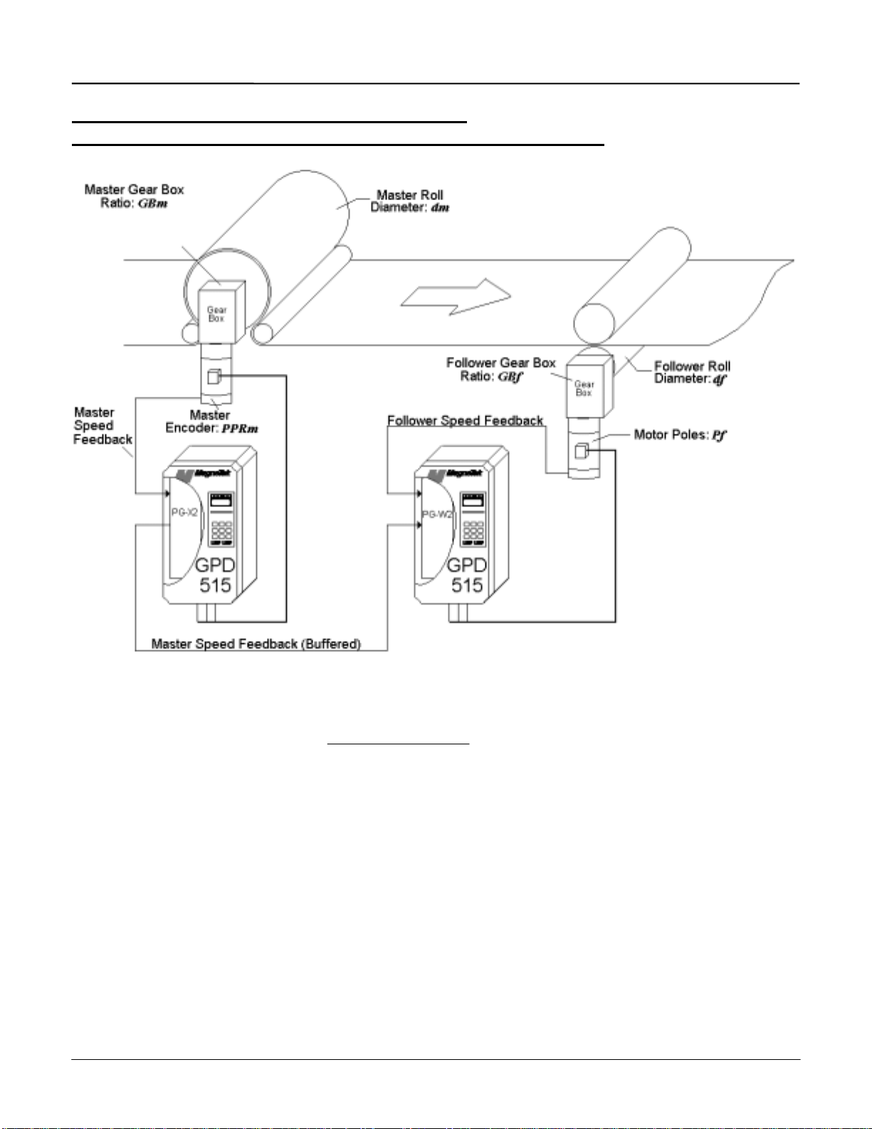
Digital Velocity Follower
Date: 07/01/04, Rev: 04-07 Page 3 of 13 TM.G5SW.045
3.0 Startup Procedure
1. Perform the appropriate procedure for start-up using Section 2.2 of the GPD515 Technical manual. Most
applications with this software utilize the flux-vector control method, which is highlighted in Section 2.2b.
2. Set the reference source to “Pulse Reference” (b1-01 = 5).
3. Set the “Following Method” as desired (see Figure 1). With a setting of “1-direction” (P2-01 = 0) and the master
running forward, the follower motor will run forward. When the master runs in reverse, the follower will stay at
zero speed. With a setting of “Bi-directional” (P2-01 = 1) the follower will run whichever direction the master is
running. A setting of “Absolute” (P2-01 = 2) will result in the follower running forward regardless of the master’s
direction.
Figure 1: Parameter P2-01 Description
4. Parameters P1-01, P1-02, and P1-03 can be calculated and set in many ways. Figure 2 illustrates the effect
those parameters will have on the follower’s frequency reference. When it is desired to have the follower motor
shaft turn at exactly the same speed as the master encoder, use Table 1 below.
Table 1: Common Settings for Parameters P1-01 thru P1-03
Master
Encoder PPR Follower
Motor Poles P1-01
Setting P1-02
Setting P1-03
Setting
1024 2 125 128 0.00
2048 2 125 256 0.00
2500 2 2 5 0.00
1024 4 125 64 0.00
2048 4 125 128 0.00
2500 4 4 5 0.00
10000 4 1 5 0.00
1024 6 375 128 0.00
2048 6 375 256 0.00
2500 6 6 5 0.00
10000 6 3 10 0.00
• If the above table does not include your specific setup, use the following formula to determine the settings of
P1-01, P1-02 & P1-03.
P1-01 = Number of Motor Poles (Follower Motor) * 500
P1-02 = Pulse Generator PPR (Master Encoder)
P1-03 = 0
If a ratio different from 1 : 1 is needed, use the following equation:
X : Y - Where X = Master Encoder Revolutions and Y = Follower Motor Revolutions
P1-01 = Number of Motor Poles (Follower Motor) * 500 * Y
P1-02 = Pulse Generator PPR (Master Encoder) * X
P1-03 = 0
5. Verify that the master reference encoder is working. Bring up parameter U1-01 on the digital operator by
pressing MENU then DATA/ENTER. When the master reference encoder is moving, a non-zero frequency
reference should show up here. If not, troubleshoot encoder wiring, or verify that P2-01 is not set to 0 (One
direction).