1
I. Features
1. Adopts PID programmable temperature control technology with an implant able
highest-precision PID program for high-speed tracking and detection of actual
desoldering gun and soldering iron temperatures with real-time temperature
correction. Miraculous temperature compensation speeds allow for minimal
temperature error for temperature stability and compensation speeds.
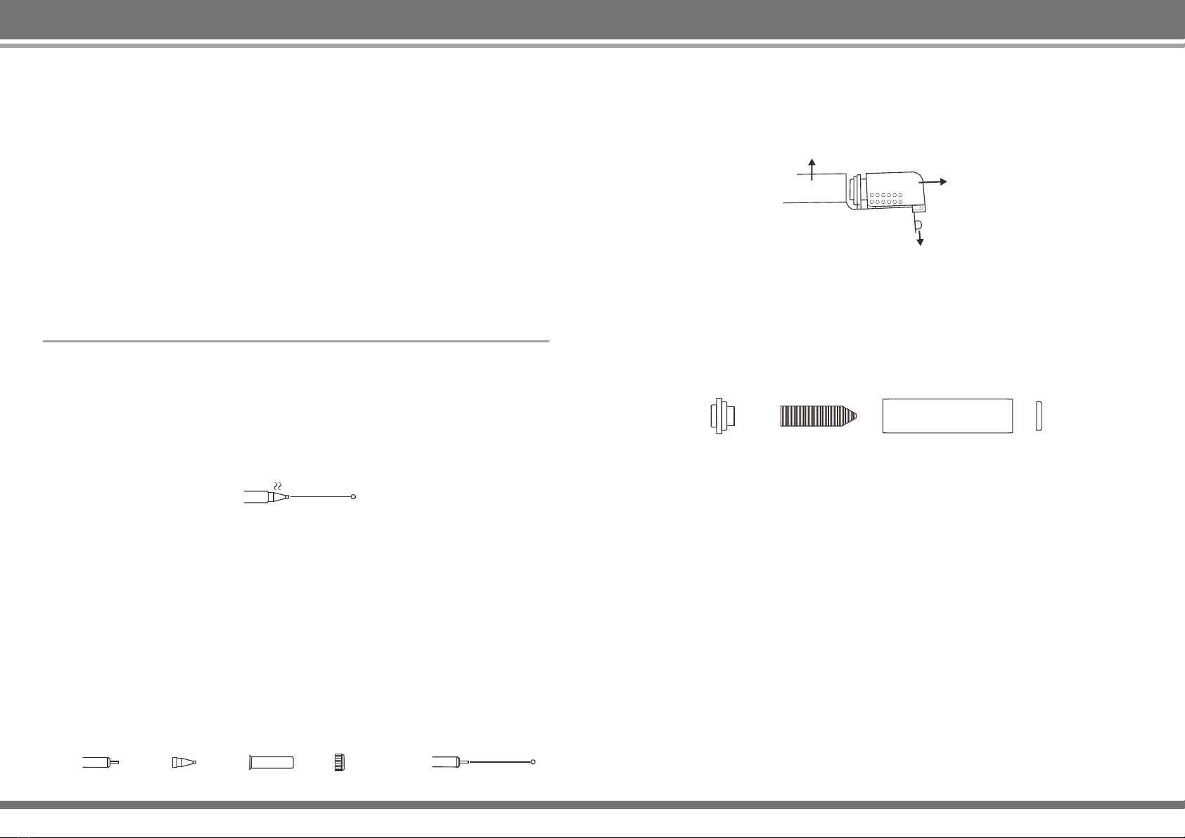
2. Featuring desoldering station and high-frequency soldering station functions,
the machine intelligently identifies and switches between the two functions.
When ready to use the high-frequency soldering station, unplug the desoldering
station handle and connect the high-frequency station handle. The machine will
intelligently identify the function and read out the high-frequency soldering
station’s previous temperature parameters. If you need to change back to the
desoldering station, unplug the high-frequency soldering station handle and
connect the desoldering station handle. The machine will automatically identify
the desoldering station temperature parameters.
3. Provided with soldering iron for wider range desoldering and it can work with
desoldering station at the same time.
4. Anti-static design, preventing components from damage due to static and
leakage.
5. Adopts an isolation transformer for power supply to heating elements and
automatic shutoff functionality when the high-frequency soldering iron handle
or desoldering gun handle is removed for safety and reliability.
6. Portable built-in vacuum with strong suction does away with external vacuum
systems.
7. This device has the following user-friendly design features.
A. Celsius/Fahrenheit Temperature Display
Designed to meet the market needs of different regions, the temperature
display function can be set to display either Celsius or Fahrenheit, depending
on local practices.
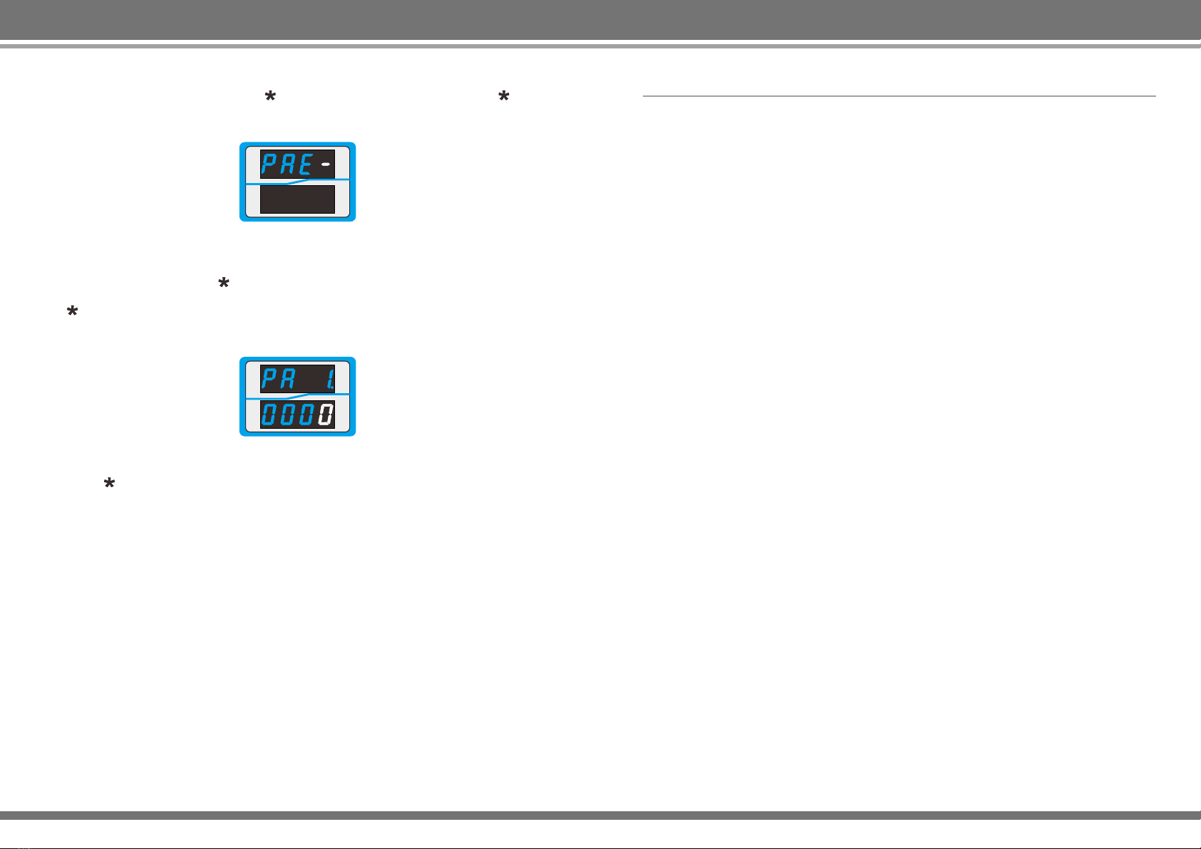
B. Sleep Function
Soldering iron automatic detection of their work status are not in use in a
quiescent state, arriving to set the sleep time, the temperature of the iron
automatically lower the temperature to 200 ° C enter into sleep state, can
effectively prevent the oxidation of iron head and prolong the iron tip service
life, energy saving and environmental protection. The sleep time can be set
range: 1 to 99 minutes in 1 minute steps, users can be set based on usage, if
you do not need a soldering iron sleep ,the sleep time is set to---.
Wake/Sleep Mode:
a. Shake soldering handle up and down several times or flick the red switch on
the suction gun once.
b. Press any one button.
c. Turn off the power switch then turn on the power switch.
C. Automatic Shutdown Function
After machine enter into sleep state, start the timer program, set the shutdown
time did not wake up from sleep, automatic shutdown, energy saving and
environmental protection. Auto power off time setting range: 1 to 99 minutes in
1 minute steps, if you do not need a auto shutdown function ,the power off time
is set to---.
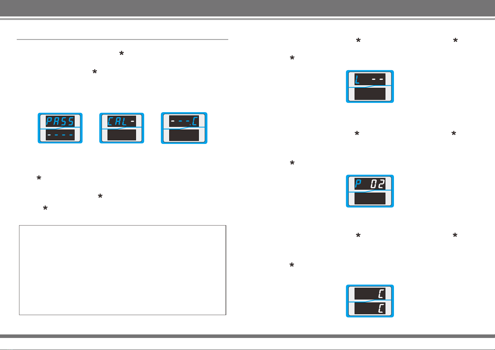
D. Password Feature
A password must be given to enter the function parameter settings. Function
parameters can only be changed after the correct password has been entered,
thus preventing operator changes and any impact on operational efficiency.
2
1. If the power cable is damaged, it must be replaced by the manufacturer or by a
maintenance department professional in order to avoid danger.
2. This tool must be placed in its stand when not in use.
3. Be careful when using this device in the vicinity of flammable materials; Never
use this device for extended periods in the same location.
4. Be aware that heat may be transferred to distant flammable materials;
Someone must be present at all times while the device is connected.
5. This device is not intended to by operated by individuals with diminished
physical, sensory, or mental capacities or by those who lack experience (such
as children), except in the presence of individuals qualified to provide
necessary supervision and guidance; Ensure that children do not play with this
device.
WARNING
To use this product, the following basic measures should be strictly followed to
avoid hazards of electric shock, bodily injury, fire and other phenomenon.
1. In order to ensure safety, please turn off the power switch when not in use.
When not in use for an extended period, please unplug the power cord!!!
2. Serious consequences may result if non-original or non-approved parts are
used.
3. In the event of product failure, repairs must be carried out by professionals or
manufacturer-designated personnel.
4. This product uses three-wire grounded plug must be inserted into three-hole
grounded outlet, do not change the plug or use an ungrounded three-headed
adapter leaving poor grounding.
5. After the desoldering station is switched on, its temperature can exceed 400
degrees centigrade. Do not use near flammable or explosive objects. To avoid
burns, do not touch the metal part of the soldering iron.
6. Do not leave the work area when the soldering station is switched on.
7. The power cord must be unplugged and the iron must be allowed to cool before
installing or replacing soldering iron parts.
8. After used, remember that cooling the unit before installation.
9. The desoldering station should only be used for soldering. Do not hit the
desoldering gun station against the work surface to remove flux residues, as
doing so may seriously damage the soldering iron.
10. Soldering produces fumes, ensure there is adequate ventilation.
Safety Guidelines