YIHUA 993D User manual

English
993D
Statement: The company reserves the right to improve and upgrade products,
product specifications and design are subject to change without notice.
Tha n ks for p ur chas ing thi s i nt elli gent re work s ta tion , th is pro du ct is spe cifi call y
des i gned for lea d -fre e wel d ing, ple as e rea d inst ruct ions c aref ully b efor e u sing .
Aft e r r eadi ng , p le ase ke ep i t f or f utur e re fere nc e.
INSTRUCTION MANUAL
High-power
Touch-screen rework station

1
Safety Guidelines
To use this product, the following basic measures should be strictly followed to
avoid hazards of electric shock, bodily injury, and fire.
1. To ensure personal safety, please turn off the power switch after power
work is completed; if it will not be used for a long time, please unplug the
power cord! !!
2. Failure to use parts approved or recommended by the manufacturer may have
serious consequences.
3. Power failure must be fixed by professionals or by maintenance personnel
designated by our company.
4. This product uses a three-wire grounded plug that must be inserted into a
three-hole grounded outlet. Do not change the plug or use an ungrounded
three-headed adapter as it will cause poor grounding.
5. After the soldering station is switched on, its temperature can exceed 400
degrees centigrade. Do not use near flammable or explosive objects. To avoid
burns, do not touch the metal part of the soldering iron.
6. Do not leave the work area when the soldering station is switched on.
7. The power cord must be unplugged and the iron must be allowed to cool before
installing or replacing soldering iron parts.
8. The soldering iron should only be used for soldering. Do not hit the soldering
iron against the work surface to remove flux residues, as doing so may
seriously damage the soldering iron.
9. Soldering produces fumes, ensure there is adequate ventilation.
WARNING
1. If the power cable is damaged, it must be replaced by the manufacturer or by a
maintenance department professional in order to avoid danger.
2. This tool must be placed in its stand when not in use.
3. Be careful when using this device in the vicinity of flammable materials; Never
use this device for extended periods in the same location.
4. Be aware that heat may be transferred to distant flammable materials;
Someone must be present at all times while the device is connected.
5. This device is not intended to by operated by individuals with diminished
physical, sensory, or mental capacities or by those who lack experience (such
as children), except in the presence of individuals qualified to provide
necessary supervision and guidance; Ensure that children do not play with this
device.
2
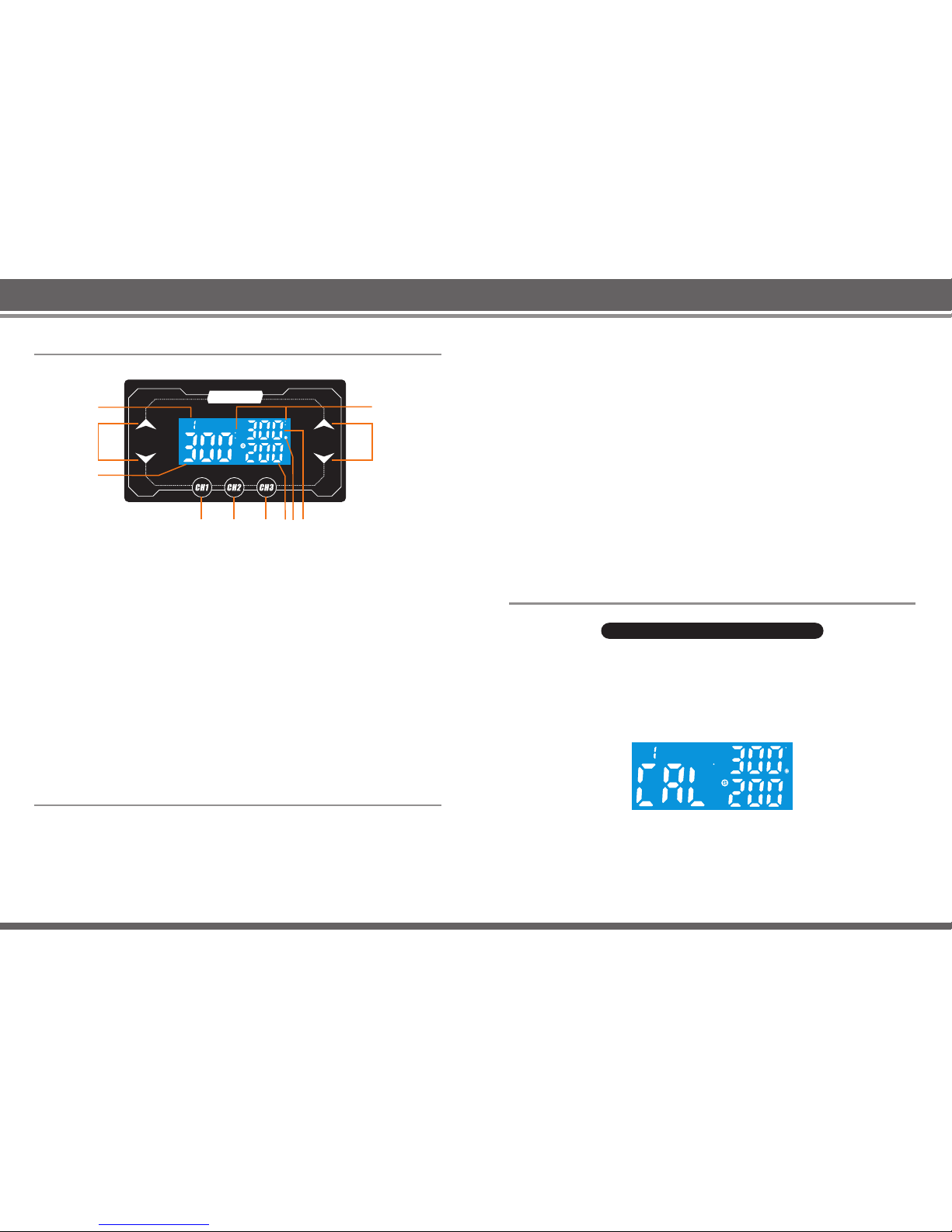
1. Uses touch screen technology, stylish and convenient to use
2. Features 3 working channels, allowing storage at different temperature and air
flow parameters; parameters can be quickly selected based on the IC type
3. Features Fahrenheit/Celsius display switch and digital calibration.
4. Closed loop sensor, no-touch temperature control by microcomputer, high
output, rapid heating; temperature regulation is convenient and precise.
5. Uses brushless vortex blower with large airflow, adjustable.
6. System features automatic cold air function, prolonging the life of the heating
element and protecting the handle.
I. Product Features
1. Suitable for soldering of many types of original parts, including SOIC, CHIP,
QFP, PLCC, and BGA.
2. Suitable for heat shrinkage, drying, paint removal, adhesive removal, thawing,
preheating, disinfection, and plastic welding.
3. Suitable for heating using different levels of airflow and heat.
4. Suitable for lead free hot air reworking.
II. Usages
III. Parameters
Power
Voltage range
Temperature range
Air volume stalls range
Maximum air flow
Dimensions (length x height x width)
Weight (including handle bracket)
Working environment
Storage environment
Storage Humidity
1300W
200V~240V 50Hz ~ 60Hz
100°C to 500°C
6 ~ 200
200L / min
230x205x170mm
about 4.5kg
0~40°C / 32~104°F
-20~80°C / -4~176°F
35% to 45%

1. Memory channel indicator
2. Temperature/data plus-minus setting
3. Temperature setting
4. Memory channel CH1 setting /digital temperature calibration button
5. Memory channel CH2 button
6. Memory CH3 button/ °F\°C switch
7. Air analog value
8. Operating light
9. Actual temperature
10. Air plus-minus button
11. °C /°F display mode (displays only one mode)
IV. Panel Diagram
C
F
C
F
CH
AIRTEMP.
1
2
3
456789
10
11
993D
1. Set up the rework station, place the handle on the handle holder. If you want to
use the holder while working, fix the handle to the holder.
2. Connect the power cord and fit the required nozzle (recommend using a large
nozzle)
3. Switch on the power.
4. Set the desired temperature and air flow (provided requirements for the task
are met, try to use low temperatures and a large air flow in order to extend the
life of the heating element and ensure safety when desoldering chips).
V. Operating Instructions
3 4
5. Lift the handle of the rework station, so the station start normal heating
operations; start work when constant temperature is reached.
6. On completion of work, place the handle back in the holder. The rework station
will automatically cut off power to the heating wire and enter the cooling
heating element mode. When the temperature is below 100°C, the display
shows “---”, air flow is stopped and the rework station enters standby mode.
7. The power switch should be switched off if the rework station is not used for a
long period of time.
1. Turn on the power switch and set the temperature to be corrected, usually set
to 300°C, and set air flow to the maximum.
2. Start the air gun, place the handle to the air gun test instrument to measure the
temperature, when a constant temperature is measured press the CH1 button
for 3 seconds and the display below will be shown. Enter the calibration mode.
If no operation is carried out for 12 seconds, the original setting will be retained
and the rework station is returned to settings mode.
3. Press the temperature/data plus-minus button to enter the temperature on the
temperature control instrument and press CH1 to confirm. Automatic
calibration of temperature, save temperature, restore temperature calibration
state, temperature calibration complete.
Note: In case of a small deviation following temperature calibration, the
process can be repeated.
VI. Description of Function Settings
Digital temperature correction setting
C
C
CH

1. Turn on the power switch
2. Press CH3 button for 3 seconds and the display below will be shown. If no
operation is carried out for 12 seconds, the original setting will be retained and
the rework station is returned to settings mode.
3. Press temperature/data plus-minus button to switch between Fahrenheit or
Celsius temperature display mode, and press CH3 to confirm. The setting will
be automatically saved and the rework station is returned to settings mode.
Switch between Fahrenheit/Celsius temperature display
5 6
S-E Sensor Error: If any part of the sensor or sensor circuit fails, the
temperature parameter window will display “S-E” to be conveyed to the
handle in order to cut off the electric current, after which the system will
stop working.
H-E Heated Element Error: If the system cannot supply power to the heating
element of the handle, the temperature parameter window will display the “
H-E” symbol, which means the heating core may already be damaged.
ERR Motor Error: If any part of the motor or electric circuit fails, the air volume
parameter window will display the "ERR" symbol, to be conveyed to the
motor in order to cut off the electric current, after which the system will stop
working.
8. Do not touch the heat pipe or directly spray someone's face with hot air, as
there is a risk of burning the human body. When it is just started, white smoke
may be emitted - this is a normal occurrence, which will later disappear.
9. When replacing the heating element, be careful not to damage the ground
wire.
10. During replacement, pay attention to the order and color of the connection
cable. Never make a mistake in the connection!
11. Please replace with the same model of heating element or heating core.
Special Note:
Hello, dear user! Because the machine air gun and the soldering iron handle use
high-strength stainless steel tube, in the production process the machine must go
through inspection or calibration four times under normal working conditions. The
cylinder will turn slightly yellow due to high temperature. When the new machine
is disassembled or used, and slight yellowing is discovered around the steel
cylinder, this is to be regarded as normal occurrence, so please remain at ease
when using it!
When a problem occurs with the equipment, the system will display a variety of
error symbols and an alarm sound will be emitted until the system power is cut off.
If the following symbols are displayed, please follow the prompts to troubleshoot
them.
VIII. Error Symbols
VII. Terms of Use
1. When turning on the power supply air gun, the handle must be placed on the
handle holder.
2. Please keep the air vent open and free of obstructions.
3. After completion of work, the heating handle must be placed on the handle
holder. Let the machine cool down by itself until it displays “---” (stop air
supply) to be able to turn off the air gun power switch.
4. When using a smaller nozzle other than the standard machine nozzle, you
must adjust the air flow to the max and to use lower temperatures within a
short period of time. Avoid long-term use of the air gun as it causes damage.
5. In accordance with work needs, choose the right air nozzle. Different air
nozzles may have slightly different temperatures. The distance between the
outlet and the object is at least 2 mm.
6. Do not forcefully install the nozzle or use pliers to pull the nozzle edge. Do not
tighten the screw firmly.
7. Before installing the nozzle, both the heat pipe and the nozzle must be cooled
first.

1. Memory channel indicator
2. Temperature/data plus-minus setting
3. Temperature setting
4. Memory channel CH1 setting /digital temperature calibration button
5. Memory channel CH2 button
6. Memory CH3 button/ °F \°C switch
7. Air analog value
8. Operating light
9. Actual temperature
10. Air plus-minus button
11. °C /°F display mode (displays only one mode)
IV. Panel Diagram
C
F
C
F
CH
AIRTEMP.
1
2
3
456789
10
11
993D
1. Set up the rework station, place the handle on the handle holder. If you want to
use the holder while working, fix the handle to the holder.
2. Connect the power cord and fit the required nozzle (recommend using a large
nozzle)
3. Switch on the power.
4. Set the desired temperature and air flow (provided requirements for the task
are met, try to use low temperatures and a large air flow in order to extend the
life of the heating element and ensure safety when desoldering chips).
V. Operating Instructions
7 8
5. Lift the handle of the rework station, so the station starts normal heating
operations; start work when constant temperature is reached.
6. On completion of work, place the handle back in the holder. The rework station
will automatically cut off power to the heating wire and enter the cooling
heating element mode. When the temperature is below 100°C, the display
shows “---”, air flow is stopped and the rework station enters standby mode.
7. The power switch should be switched off if the rework station is not used for a
long period of time.
1. Turn on the power switch and set the temperature to be corrected, usually set
to 300°C, and set air flow to the maximum.
2. Start the air gun, place the handle to the air gun test instrument to measure the
temperature, when a constant temperature is measured press the CH1 button
for 3 seconds and the display below will be shown. Enter the calibration mode.
If no operation is carried out for 12 seconds, the original setting will be retained
and the rework station is returned to settings mode.
3. Press the temperature/data plus-minus button to enter the temperature on the
temperature control instrument and press CH1 to confirm. Automatic
calibration of temperature, save temperature, restore temperature calibration
state, temperature calibration complete.
Note: In case of a small deviation following temperature calibration, the
process can be repeated.
VI. Description of Function Settings
Digital temperature correction setting
C
C
CH
Table of contents
Other YIHUA Soldering Gun manuals