YitaHome IMISSB-0003 User manual

ASSEMBLY INSTRUCTIONS
SAFE BOX
HNXD-V1
IMISSB-0003

ASSEMBLY INSTRUCTIONS
1
B
C
D
Item no. Reference Image Qty.
X1
X6
X1
1.Confirm all parts are present prior to assembly.
2.Do not lock the emergency key or emergency battery box into the cabinet.
AX2
Emergency key
Emergency battery box
Expansion screw
Fireproof bag

ASSEMBLY INSTRUCTIONS
2
1.Position the cabinet near the wall and mark the locations of the anchor holes
using a marker.
2.Use a hammer drill to create holes at the marked positions.
3.Move the cabinet to its designated location and insert expansion screws into
the drilled holes with a hammer.
4.Tighten the expansion screws securely to complete the installation.
How to Mount the Safe:
1
3
2
4

ASSEMBLY INSTRUCTIONS
3
User Manual for Electronic Lock
First-Time Safe Setup:
1. Unfasten the right side panel and use the emergency key to open the safe.
(The first time to open the key cover is tight, press the right edge position,
need to use a little more force.)
2. Install the batteries.
3. Set the password (refer to the detailed instructions in the following).
Lock hole cover
Display panel
Door handle
Key panel
Reset button

ASSEMBLY INSTRUCTIONS
4
User Manual for Electronic Lock
I. Initial Power-up:
1.Upon the system's first power-up, the initial password is set to a personal code
of "1234" and an administrative code of "123456".
2.In standby mode, the system displays the system date, time, and voltage status.
3. After a power outage, the password and records of door openings will still be
saved, but the time might be lost. Therefore, you need to recalibrate the time
after powering up again.
II. Door Opening Operation:
1.In standby mode, press the "#" key to start up the system. When the LCD screen
displays "-------", you can enter a 1 to 8 digit personal password and then press
the "#" key to confirm it. (The system will automatically confirm after entering
an 8-digit password)
2.If the password is correct, "OPEN" will be displayed, the electromagnet will be
toggled for 5 seconds, and you can open the door during this time. The internal
light will be on for 25 seconds.
3. If the password is incorrect, then "ERROR" will be displayed, followed by
displaying "------" again so you can re-enter the password.
4. If you enter the incorrect password three times in a row, the screen will display
an alarm symbol, and the alarm will sound for one minute. Entering the correct
password at this time will disable the alarm and unlock the door.
5. Clear function: During the password input process, pressing the "*" key once
will clear the last entered digit.

III. Changing Personal Password:
1.Change in "OPEN" mode: First open the door with your personal password.
When the screen displays "OPEN", press the "*" key and the system should
display "------" which means it knows you want to change your personal
password. You can now enter a new 1~8 digit personal password, then press
the "#" key to confirm (system automatically confirms after entering 8 digits).
The screen will display "in", which tells you that the password has been
successfully changed.
2.Change in "Change Key" mode: In standby mode, press the setup key, and
the LCD screen will display "------". You can now enter a new 1~8 digit personal
password, then press the "#" key to confirm (system automatically confirms
after entering 8 digits). The screen will display "in", which tells you that the
password has been successfully changed.
3.Then the screen will display the new password for 1 second before returning to
standby mode.
4.Clear function: During the new password input process, pressing the "*" key
once will delete the last entered digit.
5.If no key is pressed within 8 seconds during the password changing process,
the system will return to standby mode (and old password will remain)
ASSEMBLY INSTRUCTIONS
5
6. Stealth function: Press the "*" key before entering password to switch to
stealth function (single press enables stealth; double press disables stealth).
When stealth is enabled, subsequent number entries will not be displayed and
will be replaced with "o".
7. If no key is pressed within 8 seconds during input, the system will return to
standby mode.
8. Every instance of a successful door opening will be recorded and saved.

IV. Changing the Administrative Password:
1."OPEN" mode changing: First open the door with the administrative password.
When the screen displays "OPEN", press the "*" key, and the system will enter
the administrative password changing status, displaying "------". You can enter
a new 1~8 digit administrative password, then press the "#" key to confirm
(system automatically confirms after entering 8 digits). The screen will display
"in", indicating that the password has been successfully changed.
2."Change Key" mode changing: Press the "#" key to start, and the LCD screen
will display "-----". After pressing the "0" key twice, the screen will display the
digits "00". Press the setup key, and the LCD screen will re-display "------".
You can enter a new 1~8 digit administrative password, then press the "#" key
to confirm (system automatically confirms after entering 8 digits). The screen
will display "in", indicating that the password has been successfully changed.
3.Clear function: During the new password input process, pressing the "*" key
once will clear the last entered digit.
4.If no key is pressed within 8 seconds during modification, the modification
status will exit (the password will remain the old password) and return to
standby mode.
V. Query door access records:
1. To open the door, enter the password firstly. When the electromagnetic lock
engages for 5 seconds and the screen displays 'OPEN,' press either the '0' or
'8' key to query the previous door access records. Each record is displayed
across two screens.
2. Enter the desired date and time by directly pressing the numeric keys in the
format 'year-month-day hour:minute' (total of 11 digits). The corresponding
ASSEMBLY INSTRUCTIONS
6
G

VII. Password reset and record clearing:
1. The purpose of this function is to reset all passwords to their initial values and
clear all door access records. Please follow the steps below to perform the
operation.
2. First, disconnect the power supply and wait for the display to disappear,
indicating that the charge in the capacitors has been discharged. While
holding down the red button, press the power button to restore power.
setting digits will blink. After entering the values, the system will automatically
confirm, save the new date and time, exit the setting mode, and return to the
standby mode.
3. During the setting process, press the '*' key to go back one digit and re-enter
the value.
4. The system will validate the input numbers for their validity. Invalid values
that fall outside the specified range will not be confirmed. The valid ranges for
each parameter are as follows:
Year: 00-99 Month: 01-12 Day: 01-31 Hour: 00-23 Minute: 00-59
5. Note: When modifying the date, the system cannot automatically differentiate
between months with different numbers of days or account for leap years.
Users must ensure that the entered date is meaningful and avoid artificial
errors such as 'February 30th'.
6. If the modification is not completed and no key is pressed within 8 seconds,
the system will exit the modification mode (any changes made will be
discarded) and return to the standby mode.
7. The system includes a perpetual calendar from the year 2000 to 2099. It
automatically handles the transition between months with different numbers
of days and accounts for leap years during timekeeping.
ASSEMBLY INSTRUCTIONS
7

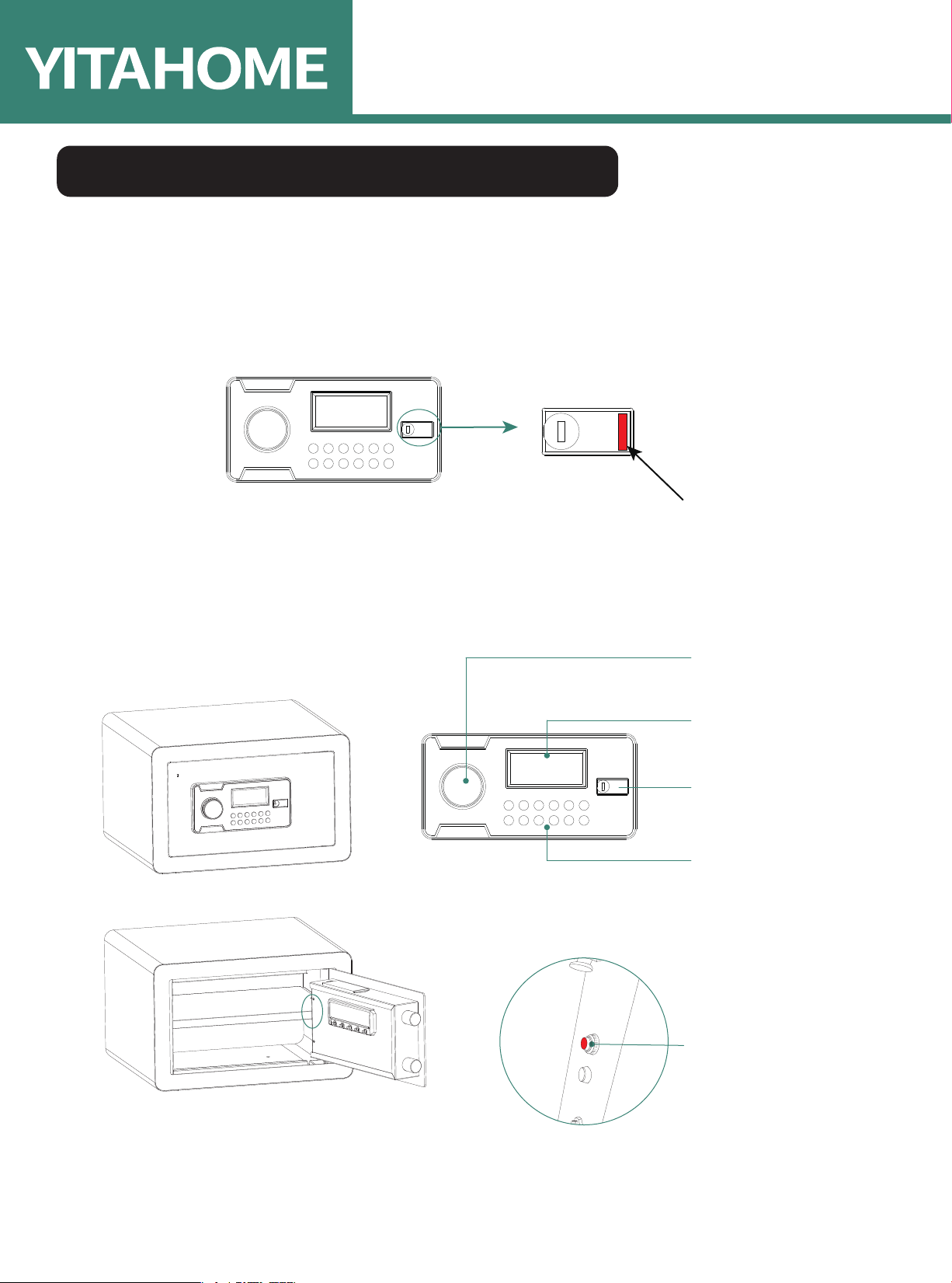
3. After powering on, if the rear screen displays 'GOOD' (you can release the red
button at this point), it means that the personal password and administrative
code have been restored to their initial values of '1234' and '123456',
respectively. Additionally, all door access records have been cleared.
IX. Power and voltage indicator:
1. Power: Uses four 1.5V alkaline batteries. When the battery is fully charged, a
solid battery icon is displayed. When the battery voltage is low (below 4.80±
0.30V), an empty battery icon is displayed, and during door opening, the screen
will show 'LO-BATTE' (low battery) to indicate low voltage and remind you to
replace the batteries.
2. Operating voltage: 4.2~7.5V
3. Operating current: 320mA
4. Static current: 35µA (at 6.0V)
5. Operating temperature: 0~50 ℃
VIII. Vibration alarm function:
1. In standby mode, press the '0' key. The screen will display 'ALert on' and enter
the alert state.
2. When the alert state is active, the safe will trigger an alarm if it detects
vibration. The screen will display an alarm bell symbol and '------' to indicate
the alarm.
3. In this case, enter the correct password. The screen will display 'OPEN', the
alarm will stop, and the alert state will be lifted, allowing the safe to be
unlocked.
4. When the alert state is active, performing a single correct door-opening action
will cancel the alert state.
VII. Password reset and record clearing:
1. The purpose of this function is to reset all passwords to their initial values and
clear all door access records. Please follow the steps below to perform the
operation.
2. First, disconnect the power supply and wait for the display to disappear,
indicating that the charge in the capacitors has been discharged. While
holding down the red button, press the power button to restore power.
ASSEMBLY INSTRUCTIONS
8

Pure & Easy
Other YitaHome Safe manuals
Popular Safe manuals by other brands

Honeywell
Honeywell 2077D - 1.21 Cubic Foot Anti-Theft Safe Operations & installation guide

Challenge
Challenge 701-5359 Operating manual instructions

Stack-On
Stack-On PS-1808-E instructions

Masterlock
Masterlock LFW082FTC owner's manual

Arregui
Arregui Supra 240090 manual

Sandleford
Sandleford DS200 instructions