3IM77J01T21-01E 5th Edition
4. DESCRIPTION OF FRONT PANEL AND
CONNECTION OF SETTING TOOLS
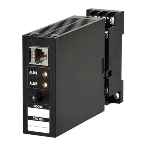
4.1 Front Panel
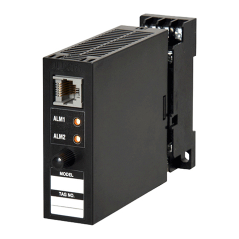
The communications connector on the front panel is used for
setting up parameters using a PC (VJ77 PC-based Parameters
Setting Tool). The alarm indicator lamps for alarm 1 and alarm 2
light up if an alarm occurs.
Alarm indicator lamp
(for alarm 1)
Communication connector
Alarm indicator lamp
(for alarm 2)
4.2 Connecting the Setting Tools
Connect the modular jack conversion adapter to the JUXTA
communication cable with 5-pin connector and then connect this
adapter to the communication connector of JUXTA.
JUXTA
VJ series
conversion
adapter
Dedicated adapter for VJ77
(L4506HA)
Micro USB (USB2.0) cable
• Use the VJ77 of version R2.02.01 or later.
5. SETTING PARAMETERS
Set the parameters using a PC (VJ77 PC-based Parameters
Setting Tool). Refer to the list of parameters in this manual and
the user’s manual for VJ77 PC-based Parameters Setting Tool
(IM 77J01J77-01E).
CAUTION
For the input sensor type, input type and temperature
unit, the default values of the input range, alarm setpoints
and others are pre-dened according to the values to be
selected. Set the parameters as follows.
1. Settings related to inputs: Set the parameters in order
starting with (1).
(1) Input type
(2) Temperature unit
(3) Input range
2. Before setting the parameters related to alarm output
and making the adjustments such as wiring resistance
correction and output correction, set the parameters
described in 1 above.
If setting the parameters (1) to (2) in 1 above after set-
ting the parameters related to alarm output or making
the adjustment, the setpoint will be changed or the
adjustment will be reset to the default.
5.1 Settings Related to Input
5.1.1 Input Type and Temperature Unit
Select the thermocouple type to use from among K, T, E, J, R,
S, B, N, W3 and W5 in [D08: TC TYPE].
Select the temperature unit to use in [D21: UNIT].
5.1.2 Input Range
Set the 0% value of input range in [D24: INPUT1 L_RNG]
and the 100% value of input range in [D25: INPUT1 H_RNG]
numerically within the following specied range.
Input type (TC) Measurable range (°C)
JIS C 1602, IEC 60584-1 (ITS-90) TYPE K -270 to 1372
JIS C 1602, IEC 60584-1 (ITS-90) TYPE T -270 to 400
JIS C 1602, IEC 60584-1 (ITS-90) TYPE E -270 to 1000
JIS C 1602, IEC 60584-1 (ITS-90) TYPE J -210 to 1200
JIS C 1602, IEC 60584-1 (ITS-90) TYPE R -50 to 1768
JIS C 1602, IEC 60584-1 (ITS-90) TYPE S -50 to 1768
JIS C 1602, IEC 60584-1 (ITS-90) TYPE B 0 to 1820
JIS C 1602, IEC 60584-1 (ITS-90) TYPE N -270 to 1300
Type W3(Note 1) 0 to 2300
Type W5(Note 2) 0 to 2300
Note 1: W3 is the abbreviation of W97Re3-W75Re25 (tungsten97
% rhenium 3 % - tungsten75 % rhenium25 %) ASTM E988
Standard
Note 2: W5 is the abbreviation of W95Re5-W74Re26 (tungsten95
% rhenium 5 % - tungsten74 % rhenium 26 %) ASTM E988
Standard
5.1.3 Software Filter
Set the software lter in [D57: S/W FILTER].
OFF, LOW, MIDDLE, HIGH (default value: OFF)
When LOW, MIDDLE, or HIGH is selected, a rst-order lter
equivalent to 100 ms, 300 ms, or 1 s is inserted in the input.
5.1.4 Setting Burnout Action
Set the burnout action in [D39:BURN OUT]. Set “OFF”, “UP”,
or “DOWN.”
CAUTION
• Changing the burnout action direction resets the input
adjusted value and the wiring resistance corrected
value.
• Changing the input range resets the input adjusted
value.
• Execute the wiring resistance correction when the
burnout action direction or input wiring is changed.
5.1.5 Wiring Resistance Correction
When an error occurs due to the inuence of the input wiring
resistance, the input can be corrected. Apply a stable input as
shown below and select EXECUTE in [P01: WIRING R]. The
correction is also required when the direction of burnout action
is changed from UP (DOWN) to DOWN (UP) or the wiring for
input is changed.
VJTK
VJ77
Short-circuit at the cable end.
5.2 Settings Related to Alarm Output
5.2.1 Alarm Setpoint
Set the alarm setpoints of alarm 1 and alarm 2 in [E01: SET
POINT1] and [E02: SET POINT2] numerically.
• Setting range: 0 to 100% of input range
• Setting resolution: 4 signicant digits
5.2.2 Direction of Alarm Action
Select the direction of alarm-1 action and that of alarm-2
action from among HIGH ALM (high-limit alarm) and LOW
ALM (low-limit alarm) in [E05: ALM1 ACTION] and [E06:
ALM2 ACTION].
• To activate alarm status when input signal ≥ alarm setpoint,
select HIGH ALM.
• To activate alarm status when input signal ≤ alarm setpoint,
select LOW ALM.
