Yolin YL80C User manual

1
Contents
Product name and model.....................................................................................................................2
Specifications...................................................................................................................................... 2
Appearance and dimension................................................................................................................. 2
Function overview and functional area distribution........................................................................... 4
Function Overview..............................................................................................................4
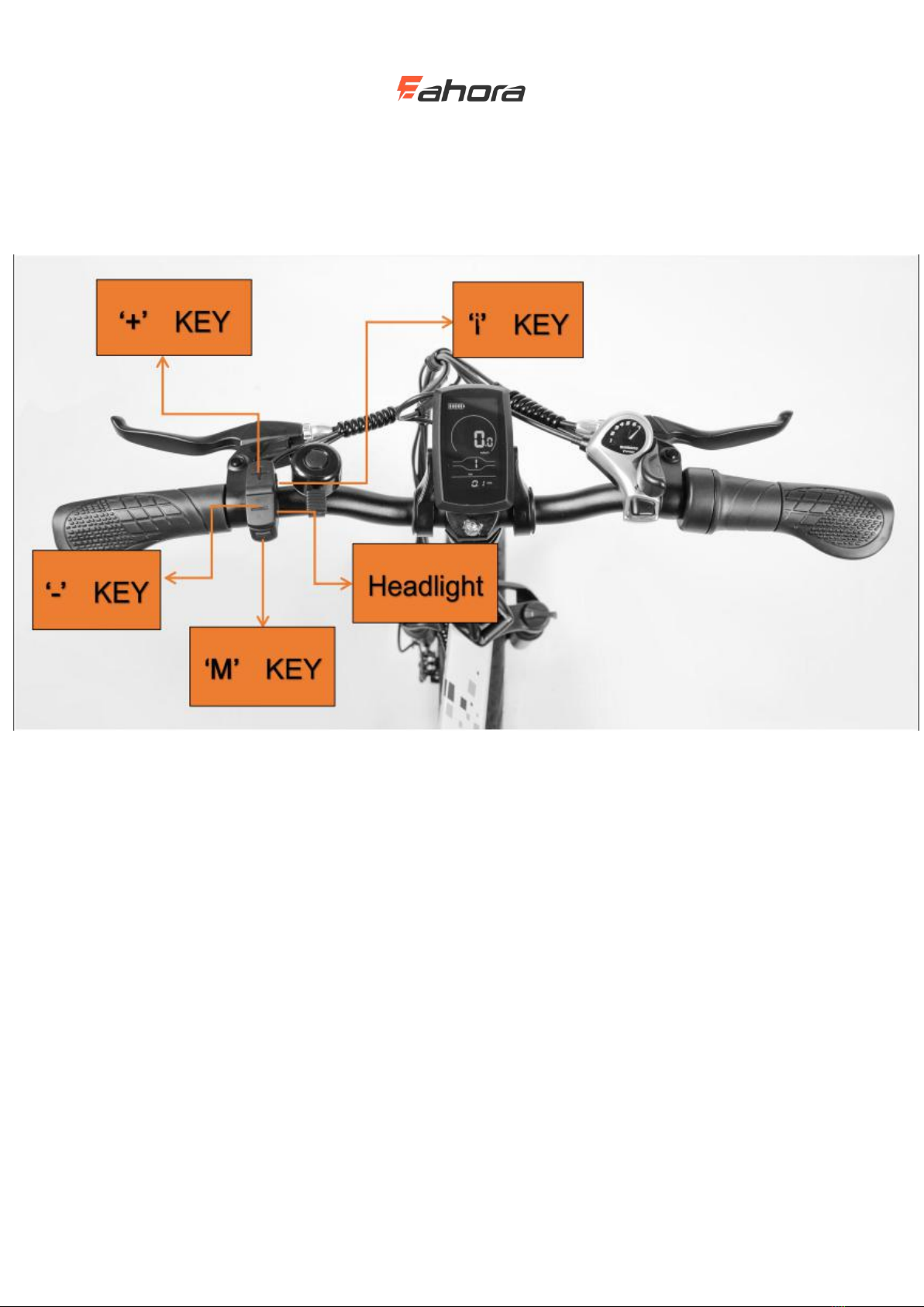
Functional area distribution................................................................................................ 5
Button definition................................................................................................................. 6
Normal operation.................................................................................................................................6
On / off................................................................................................................................ 6
UI.........................................................................................................................................6
Walk power assist................................................................................................................7
Backlight on / off.................................................................................................................8
Power assistance (PAS) level selection................................................................................8
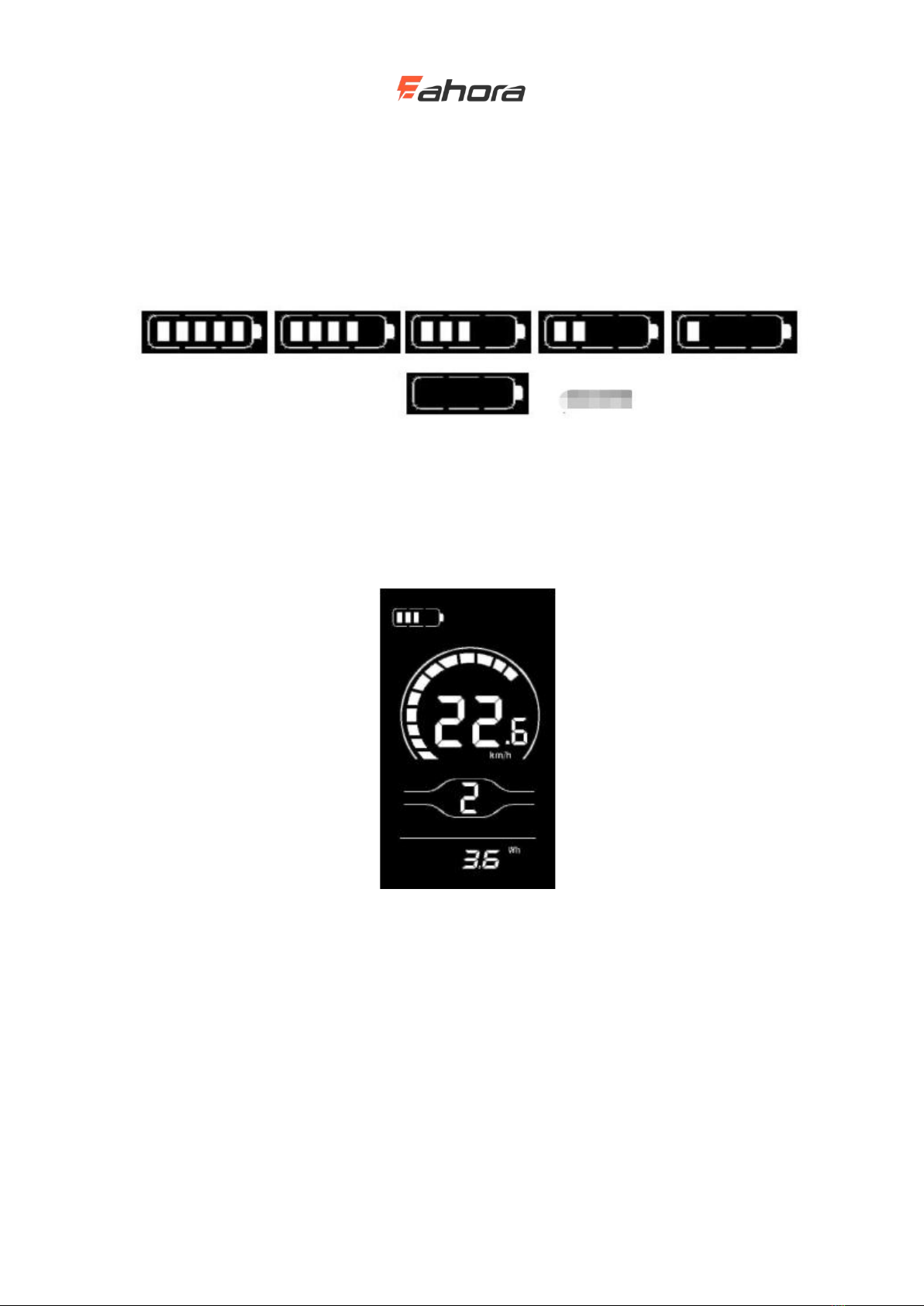
Battery bars......................................................................................................................... 9
Motor power indication.......................................................................................................9
Error code indication.........................................................................................................10
General settings................................................................................................................................. 10
Single mileage reset.......................................................................................................... 11
Backlight brightness..........................................................................................................11
Imperial and Metric Unit Conversion...............................................................................12
General parameter settings................................................................................................................13
Wheel diameter setting......................................................................................................13
Speed limit setting.............................................................................................................14
Personalization settings.....................................................................................................................14
Battery level setting...........................................................................................................15
Power assist parameter setting (optional)......................................................................... 16
Current limit value setting (optional)................................................................................17
Booster sensor setting (optional)...................................................................................... 17
Throttle setting(optional).................................................................................................. 18
System settings (optional).................................................................................................20
Power-on password setting............................................................................................... 21
Exit Settings...................................................................................................................... 22
Restore default settings..................................................................................................................... 23
Quality commitment and warranty................................................................................................... 23
Lead connection diagram.................................................................................................................. 24
Precautions........................................................................................................................................ 24
Schedule 1: Error code definition table............................................................................................ 25
Schedule 2: Table of default values for PAS level ratio................................................................... 25

2
Product name and model
Intelligent LCD meter for electric bicycle; Model: YL80C.
Specifications
24V / 36V / 48V power supply
Instrument rated working current 10mA
Maximum working current of the instrument: 30mA
Shutdown leakage current <1uA
Supply controller current 50mA
Working temperature -20 ~60 ℃
Storage temperature -30 ~70 ℃
Appearance and dimension
Physical and dimensional drawings (unit: mm)

3
Physical and dimensional drawings

4
Function overview and functional area
distribution
Function Overview
YL80C meters provide a variety of functions to meet your riding needs, including:
Battery bars
Motor power indication
Assist level adjustment and indication
Speed (including real-time speed, maximum speed, average speed)
Mileage (including single mileage and total mileage)
Walk assist mode
Backlight control and display
Error code
USB connection indication (optional)
Heart rate (optional)
Multiple parameter settings (such as: wheel diameter, speed limit, battery power setting and
boost parameter setting, power-on password setting, controller current limit setting, etc.)
Default parameter recovery function

5
Functional area distribution
YL80C functional area distribution interface

6
Button definition
There are five keys on the operation unit corresponding to the YL80C meter. The keys ‘+’ and ‘-’
are replaced with the words "UP" and "DOWN" in the following description.
Normal operation
On / off
After long pressing M, the meter starts to work, and the controller's working power is connected.
In the on state, short press Mto turn off the power of the electric bike. In the off state, the meter
no longer uses battery power, and the leakage current of the meter is less than 1uA.
If the e-bike is not used for more than 10 minutes, the meter will automatically shut down.
UI
After the display is turned on, the display shows the real-time speed and total mileage (km) by
default. Short press ‘i’ key, the displayed information can be in real time speed (km / h), single
mileage (km), total mileage (km), maximum speed (km / hour), average speed (km / Hour) and

7
cycling power.
Display interface switching
Walk power assist
Press and hold DOWN, the electric bike enters the state of electric walk power assistance. Electric
bike travel at a constant 6km/h. At the same time the screen shows . Release the DOWN,
the electric bike will immediately stop the power output and return to the state before the boost.

8
Walk power assist interface
The Walk power assist mode can only be used when the user pushes the electric bicycle.
Do not use it while riding.
Backlight on / off
Short press the headlight key, the display backlight dims, and at the same time notify the
controller to turn on the headlight. When there is insufficient external light or driving at night, the
headlights can be turned on. Press the headlight key again, the display backlight turns on and tells
the controller to turn off the headlights.
Backlit display interface
Power assistance (PAS) level selection
Short press the UP / DOWN button to switch PAS level thereby changing the motor output power.
The default output power range of the display is 0-3, 0 is 0 power output, 1 is the lowest power,
and 3 is the highest power. When the level 3 is reached, short press the UP button again, the
interface still displays 3, and the number 3 does not change, which is the highest grade. After the
assist downshift reaches the level 0, press the DOWN button again briefly, the interface still
displays 0, the number 0 does not change, and it is the lowest level. The default position of the
display when it is turned on is level 1.

9
PAS level interface
Battery bars
The battery displays 5 power bars. When the battery voltage is high, all 5 bars are on. When the
battery is under voltage, the outer frame of the battery flashes at a frequency of 1HZ, prompting
you to charge immediately.
Battery indication interface
Motor power indication
You can know the motor output power through the display. The display mode is shown in the
figure below.
Motor power indication interface

10
Error code indication
Error code indication interface
When an error code appears on the display interface, remove the fault in a timely
manner. The electric bike will not run normally after the fault occurs.
General settings
Press and hold M to power on. In the on state, when the bicycle is stationary, press and hold the
UP and DOWN buttons simultaneously for more than 2 seconds, the display will enter the general
setting state.
Each setting item needs to be set when the bicycle is stationary.

11
Single mileage reset
TC stands for Clear Single Mileage. Press the UP / DOWN button to select Y / N. Y (Yes) means
to clear the mileage of a single trip. N (No) means that the mileage of a single trip is not cleared.
Press ‘i’ key to confirm and enter the backlight brightness setting state.
Single mileage reset interface
Backlight brightness
bL stands for backlight. You can set the parameters 1, 2, and 3 to indicate the backlight brightness,
1 is the darkest, 2 is the standard brightness, and 3 is the brightest. The default value of the display
is 1. You can change the backlight brightness parameter by pressing the UP / DOWN button. Press
the ‘i’ key to confirm and enter the metric and English unit conversion setting state. Press and hold
the ‘i’ key to confirm and exit the general setting state.
Backlight brightness setting interface

12
Imperial and Metric Unit Conversion
U stands for the unit, 1 is the English system, and 2 is the metric system. The speed and mileage
units can be changed by pressing the UP / DOWN button. Press the "i" key to confirm, press and
hold the 'i' key to confirm and exit the normal setting state. The display's default unit is metric.
Imperial and Metric Unit Conversion interface

13
General parameter settings
Simultaneously press the UP + DOWN button for more than 2 seconds to enter the general setting
state. Then press the DOWN and ‘i’ simultaneously for more than 2 seconds to enter the wheel
diameter setting interface.
Wheel diameter setting
LD stands for wheel diameter, and the settable values are: 8-26, 700C, 28-30. Press the UP /
DOWN button to select the wheel diameter corresponding to the bicycle to ensure the accuracy of
the meter speed display and mileage display. The display factory default wheel diameter value is
26 inch or 20 inch. Press ‘i’ key to enter the speed limit setting interface.
Wheel diameter setting interface

14
Speed limit setting
The default value of the maximum riding speed of the display is 25Km / h. Changing this value
can set the maximum riding speed of the electric bike. When the electric power exceeds the set
value, the controller will stop the power supply to the motor to protect the rider's driving safety;
LS stands for speed limit. The selectable range of the maximum speed setting value is between
12Km / h and 40Km / h, which can be adjusted by the UP / DOWN button. Press and hold the ‘i’
button to confirm and exit the setting state.
Speed limit setting interface
Personalization settings
In order to meet the customer's personalized usage requirements, personalized settings are set,
which include the display's battery power settings, boost parameter settings, current limit value
settings, boost sensor settings, speed sensor settings, handlebar function settings, system settings
and Power-on password settings, a total of eight settings. At the same time, press and hold the UP
and DOWN buttons for more than 2 seconds to enter the normal setting state; Then press and
hold the UP and DOWN buttons for more than 2 seconds at the same time again to enter the
display personalization item selection interface;
Select the content to be set by UP / DOWN, and press ‘i’ key enters the corresponding setting
interface.
Ensure you do not change Personalization settings. Changing Personalization settings
may cause your bike to stop working properly. If you need the default settings for the
advanced settings menu, please contact Eahora.

15
Personalized item selection interface
Battery level setting
VOL stands for voltage, and requires 1 to 5 voltage values to be input one by one. Take the first
power value as an example: "1" on the screen indicates the first voltage, and "34.5" is the first
power value. Press the UP / DOWN button to increase / decrease the value, press ‘i’ key to
confirm and enter the next section of power setting interface; after setting the 5 power values,
press and hold ‘i’key to confirm and return to setting item selection interface of the display.

16
Battery level setting interface
Power assist parameter setting (optional)
PAS levels selection
Eight modes are provided in the PAS levels selection: 0-3, 1-3, 0-5, 1-5, 0-7, 1-7, 0-9, 1-9; by UP /
DOWN and press the ‘i’ key to confirm and enter the assist ratio value setting interface in the
corresponding mode. The display's default mode is 0-3.
PAS levels selection interface
PAS ratio value setting
By setting the assist ratio value, the speed of each level can be adjusted to meet the same needs of
non-cyclists. Take the level 1 as an example, “45-55%” is the range of the level 1 ratio, and “50%”
is the default value of the level 1. It is a settable value. Use the UP / DOWN button to add /
subtract the setting. Short press ‘i’ key to confirm and enter the next boost ratio setting, up to 9 can
be set. After setting, press and hold ‘i’ key to confirm and return to the setting item selection
interface of the display. Refer to Schedule 2 for details.
PAS ratio value setting interface

17
Current limit value setting (optional)
CUR stands for current limit. The current limit can be set in the range of 7.0-25.0A. Press the UP /
DOWN button to change the maximum current value of the controller. Press and hold the ‘i’ key
to confirm and return to the setting item selection interface of the display. The display's factory
default is 15.0A.
Current limit value setting interface
Booster sensor setting (optional)
Direction setting of power sensor
PAS stands for power sensor. Run-F / b is displayed on the screen. run-F stands for forward
direction, run-b stands for reverse direction. Press the UP / DOWN button to switch. Press the ‘i’
button to confirm and enter the sensitivity setting of the booster sensor. The display's factory
default value is forward.
Direction setting interface of power sensor

18
Booster sensor sensitivity setting
SCN stands for the sensitivity of the booster sensor; the setting range is 2-9, where 2 is the highest
sensitivity and 9 is the lowest sensitivity; use the UP / DOWN button to add / subtract the setting,
and press the ‘i’ key to confirm and enter the power sensor proportional parameter setting
interface. The display's factory default value is 2.
Booster sensor sensitivity setting interface
Setting magnetic disk number
SPS stands for speed sensor. It can be set according to the number of magnetic heads installed on
the wheels of electric vehicles. The setting range is 1-15; press the UP / DOWN button to modify
it, press and hold the ‘i’ button to confirm and return to the instrument setting item selection
interface. The display factory default value is 1.
Setting magnetic disk number interface
Throttle setting(optional)
Throttle boosts enable settings

19
Hnd stands for throttle, HL for turn-assisted pushing, HL-N for throttle-assisted pushing, HL-Y for
throttle-assisted pushing, that is, when turning the throttle, the display enters the boost-driven
mode; by UP / DOWN You can switch Y / N, press the ‘i’ key to confirm, if you select N, you will
enter the throttle position enable setting interface; otherwise, you will return to the display
instrument setting item selection interface. The display's factory default value is N.
Throttle setting interface
Throttle gear enable setting
HF-Y stands for throttle step, HF-N means throttle is not stepped. If throttle step is selected, it
means that when turning the throttle, the maximum speed can only reach the corresponding speed
corresponding to the gear position displayed on the meter. Split, it means that when turning the
throttle, it is not limited by the gear on the display, and can reach the rated maximum speed. You
can set Y / N by pressing the UP / DOWN button. Press the "i" key to confirm and return to the
throttle to assist the implementation. Enable setting interface; long press
“I” key to confirm and return to the setting item selection interface of the display. The factory
default value of the meter is N.
Throttle gear enable setting interface

20
System settings (optional)
Battery delay time setting
dLY stands for battery delay time. You can select the battery delay time 3/6/12s by pressing the UP
/ DOWN button. Press the ‘i’ button to confirm and enter the maximum speed setting interface.
The display's factory default is 3s.
Battery delay time setting interface
Buttons help push enable settings
PUS stands for push enable. Press UP / DOWN to switch Y / N. Y stands for enable and N stands
for disable. Short press “i” to confirm and enter the speed setting for boost. The display's factory
default is Y.
Buttons help push enable settings interface
Slow start settings
SSP stands for slow start, and the adjustable range is 1-4, 4 stands for the slowest; it can be
selected by the UP / DOWN button, press and hold “i” to confirm and exit the setting. The
Other manuals for YL80C
3
Table of contents
Other Yolin Bicycle Accessories manuals
Popular Bicycle Accessories manuals by other brands

Small Innovations
Small Innovations BlinkerGrips user guide

Sena
Sena X1 PRO quick start guide

Syncros
Syncros Revolution Crankset quick start guide

Burley
Burley PANNIER BAGS Owner's instruction and safety manual

Light & Motion
Light & Motion Vega LED light owner's manual

freibeik
freibeik 06385 operating instructions