Yolin YL81C-A User manual

Tianjin Yolin Technology Co., Ltd.
User Manual for
E-bike Display
YL81C-A

Table of Contents
1. Product name and model...............................................................................................................................................................1
2. Specifications...............................................................................................................................................................................1
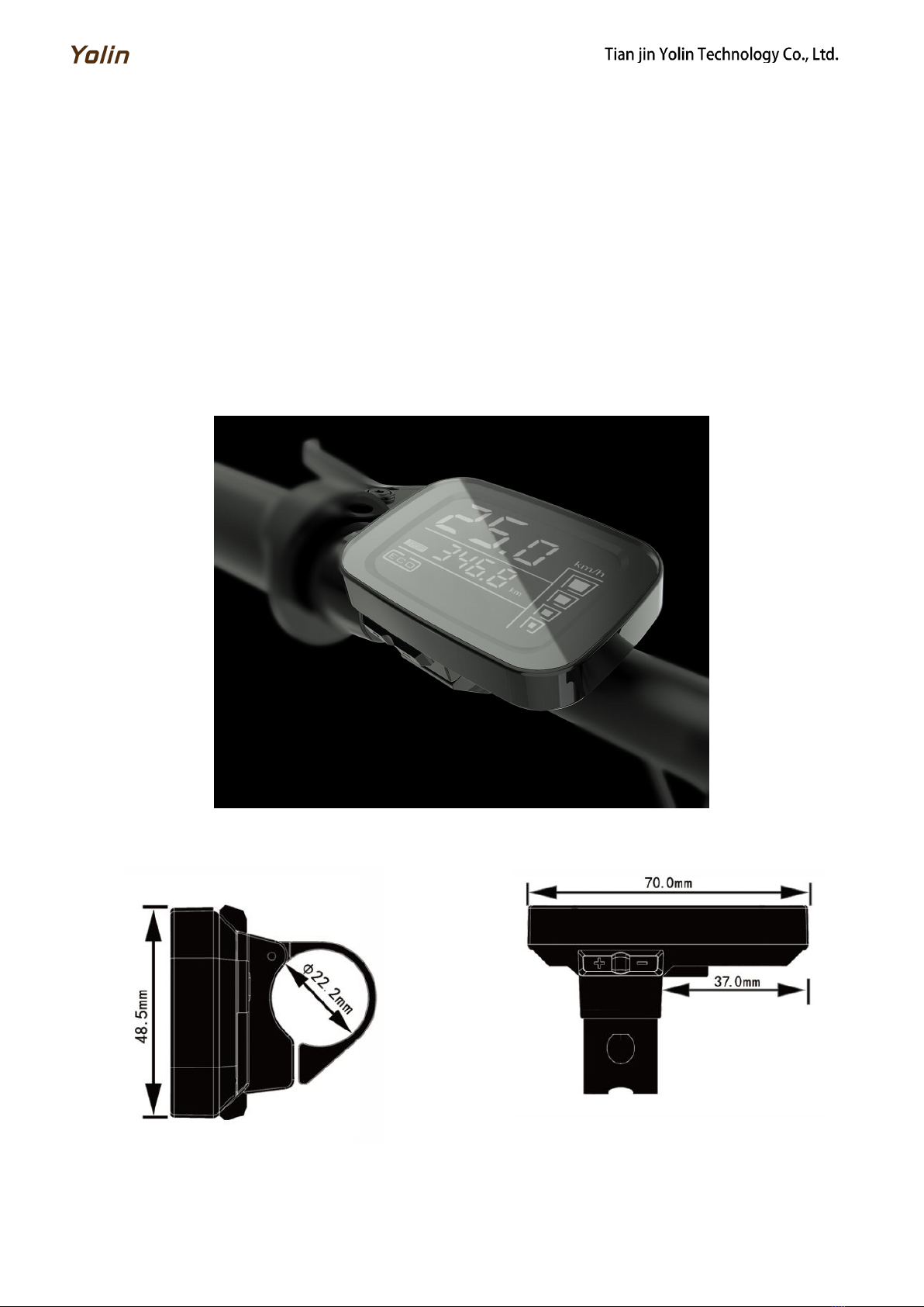
3. Appearance and dimensions..........................................................................................................................................................1
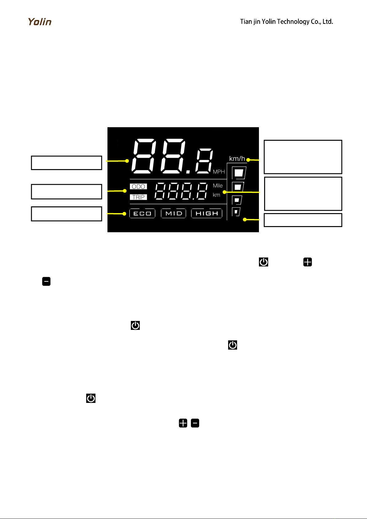
4. Function overview and functional area layout............................................................................................................................ 2
4.1 Function overview.................................................................................................................................................................... 2
4.2 Functional area layout............................................................................................................................................................. 2
4.3 Button definitions.....................................................................................................................................................................2
5. General operation ......................................................................................................................................................................... 2
5.1 Power on/off.......................................................................................................................................................................2
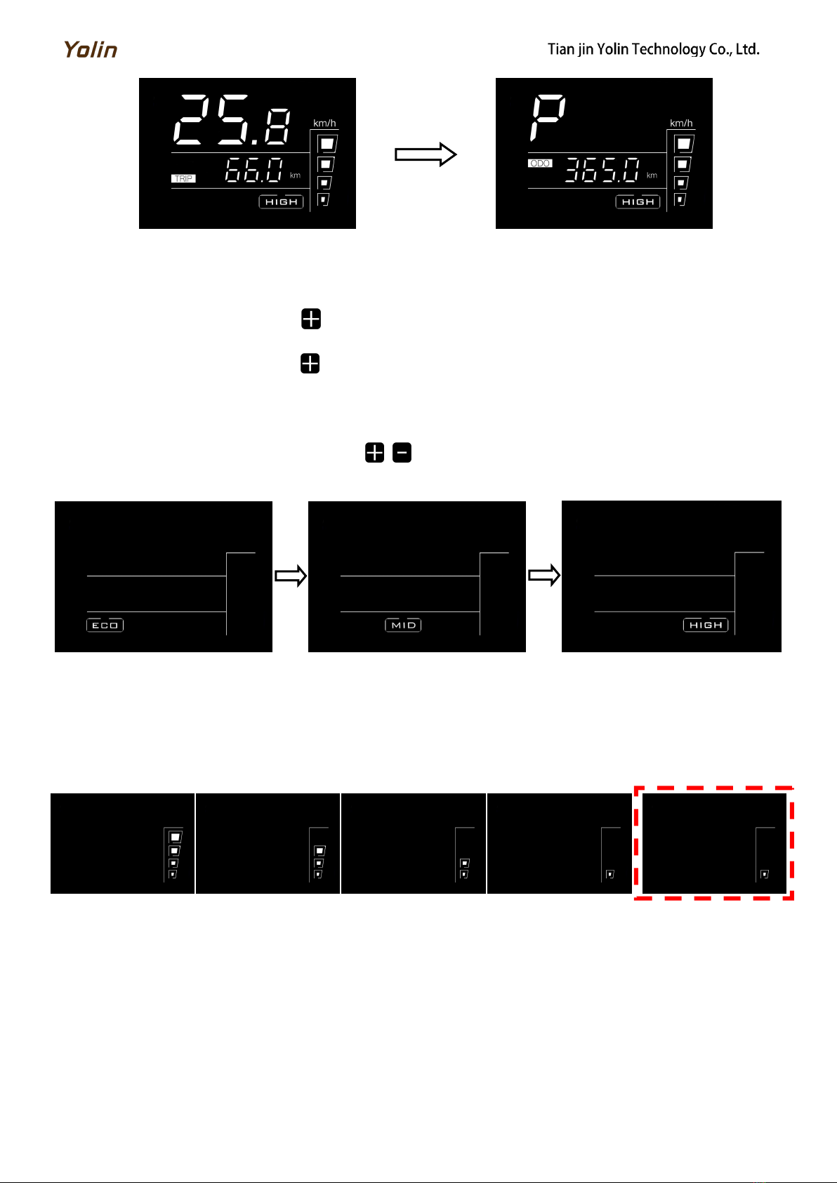
5.2 Display interface.......................................................................................................................................................................2
5.3 Headlight on/off.......................................................................................................................................................................3
5.4 Assist level selection................................................................................................................................................................. 3
5.5 Battery level indicator............................................................................................................................................................. 3
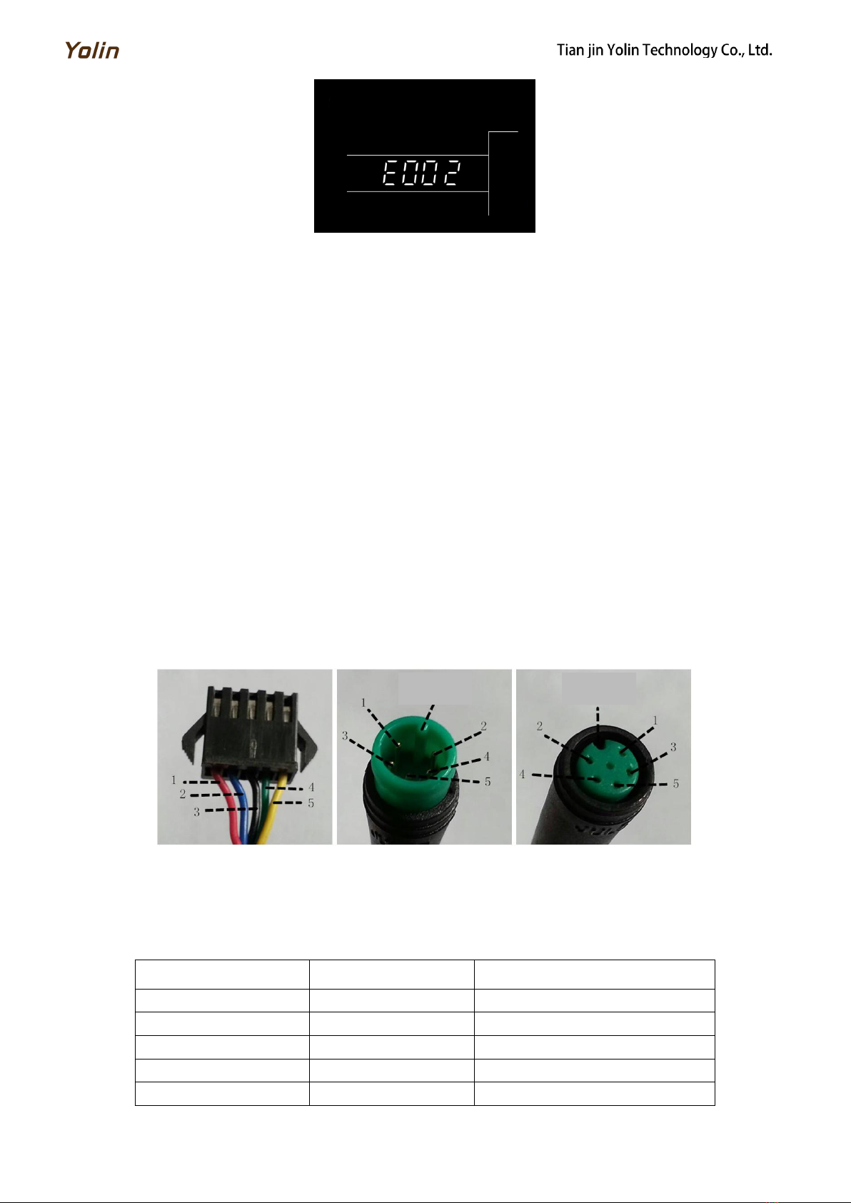
5.6 Error code indicator................................................................................................................................................................. 3
6.Quality commitments and warranty scope.................................................................................................................................... 4
6.1 Warranty information:.............................................................................................................................................................4
6.2 Non-warranty scope................................................................................................................................................................. 4
7.Outgoing line connection diagram..................................................................................................................................................4
7.1 Wiring sequence of standard connector................................................................................................................................. 4
8. Considerations...............................................................................................................................................................................5
Schedule 1 Error Code Definitions.................................................................................................................................................... 5

1
1. Product name and model
Intelligent LCD display for e-bike; model: YL81C.
2. Specifications
36V/48V power supply
Rated working current 15mA
Maximum working current 30mA
Leakage current at power-off <1uA
Working current at the supply controller end 50mA
Working temperature -20~60
Storage temperature -30~70
3. Appearance and dimensions
Fig. 3-1 Picture of Display 81C
Fig. 3-2 Top View of Display 81C Dimensions
Fig. 3-3 Side View of Display 81C Dimensions

2
4. Function overview and functional area layout
4.1 Function overview
Display YL81C provides a variety of functions to meet the riding needs of users, including:
Battery level indicator
Assist level adjustment and indication (levels ECO, MID and HIGH)
Speed indicator
Distance indicator (including trip distance and ODO)
Error code indicator
4.2 Functional area layout
Fig. 4-1 Functional Area Layout Interface of Display YL81C
4.3 Button definitions
There are three buttons on the operating unit of display YL81C, i.e., the on/off button , plus button and minus
button .
5. General operation
5.1 Power on/off
By pressing and holding the button , the display will start to work and the working power supply of the controller
will be turned on. In the power-on state, by pressing and holding the button , your e-bike will be powered off. In the
power-off state, the display will no longer use the battery power, and its leakage current will be less than 1uA.
If your e-bike is not used for more than 10 minutes, the display will be automatically powered off.
5.2 Display interface
After the display is turned on, the display will show the real-time speed (km/h) and the trip distance (km) by default.
By pressing the button , the information displayed will be switched between the trip distance (km) and the ODO (km).
When the TRIP light is on, the trip distance is displayed; when the ODO light is on, the ODO is displayed.
When the ODO is displayed, by pressing the button / , no operations will be done. The assist level is in the
parking status, and P will be displayed in the first numeric area of the speed value. When the distance reaches 9999 km, it
will be automatically reset to zero.
Speed indicator
Assist level indicator
Distance indicator
Speed unit
Metric system: km/h
Imperial system: MPH
Distance unit
Metric system: km
Imperial system: mile
Battery level indicator

3
Trip distance indicator
ODO
Fig. 5-1 Display Interface Switching
5.3 Headlight on/off
By pressing and holding the button , the controller will turn on the headlights and the display backlight will turn
dark. By pressing and holding the button again, the controller will turn off the headlights and the display backlight will
resumes the luminance.
5.4 Assist level selection
When TRIP is shown, by pressing the button / , the e-bike assist level will be switched to change the motor
output power. There are three assist levels available: ECO, MID and HIGH.
ECO indicator interface
MID indicator interface
HIGH indicator interface
Fig. 5-2 Assist Level Switching Interface
5.5 Battery level indicator
The battery level indicator consists of four segments. When the battery is fully charged, the four segments will be all
on. In case of undervoltage, the last segment of the battery indicator will flash, which means the battery has to be charged
immediately.
Full battery level indication
3-segment indication
2-segment indication
1-segment indication
Undervoltage flashing
Fig. 5-3 Battery Level Indicator Interface
5.6 Error code indicator
When a fault occurs in the electronic control system of your e-bike, the display will automatically indicate the error
code in the distance area in the format of E0**. Detailed definitions of error codes are shown in Schedule 1.

4
Fig. 5-4 Error Code Indicator Interface
When an error code appears on the display interface, please conduct troubleshooting in time. Otherwise, your e-bike will
not work normally.
6. Quality commitments and warranty scope
6.1 Warranty information:
For the faults caused by the quality of the product under normal use, the Company will be responsible for providing
limited warranty during the warranty period.
The warranty period of the product is within 12 months from delivery.
6.2 Non-warranty scope
The enclosure is opened
The connector is damaged
The enclosure is scratched or damaged after delivery
The outgoing line of the display is scratched or broken
Faults or damage caused by force majeure (such as fires, earthquakes, etc.) or natural disasters (such as lightning
strikes, etc.)
The warranty period has expired
7. Outgoing line connection diagram
7.1 Wiring sequence of standard connector
Connecting terminal to the
controller
Leading-out terminal of
display
Connecting terminal
Fig. 7-1 Outgoing Line Connection Diagram
Table 7-1 Wiring Sequence of Standard Connector
Standard wiring sequence
Standard wire color
Function
1
Red (VCC)
Power cord of display
2
Blue (Kp)
Power control line of controller
3
Black (GND)
Ground wire of display
4
Green (RX)
Data receiving line of display
5
Yellow (TX)
Data transmission line of display
Projection
Groove

5
The outgoing lines of some products adopt waterproof connectors, and users cannot see the outgoing line color
inside the wire harnesses.
8. Considerations
Please use safely, and do not plug or unplug the display when it is powered on.
Please avoid bumping as far as possible.
Please do not alter the background parameter settings of the display at will, otherwise normal riding cannot be
guaranteed.
If the display fails to work normally, it should be repaired as soon as possible.
Due to product upgrades of the Company, part of the displayed contents or functions of the product you bought may
be different from the manual, depending on the actual model.
Schedule 1 Error Code Definitions
Error codes for protocols YL-01 and YL-02:
Error codes
for
Definition
Error codes
for protocols
Definition
E001
Controller Abnormality
E004
Throttle Abnormality
E002
Communication Abnormality
E005
Brake Abnormality
E003
Motor Hall Signal Abnormality
E006
Motor Phase Abnormality
Error codes for protocols YL-05, KDS and YL-J:
Error codes
for
Definition
Error codes
for protocols
Definition
E021
Current Abnormality
E024
Motor Hall Signal Abnormality
E022
Throttle Abnormality
E025
Brake Abnormality
E023
Motor Phase Abnormality
E030
Communication Abnormality
Tel: 022-86838795 Fax: 022-86838795
Email: yolin@yolintech.com
Website: www.yolintech.com
Address: Plant 52-1, Yougu Xinke Park, East of Jingfu Road, Pharmaceuticals and Medical Equipment Industrial Park, Beichen
Economic Development Zone, Beichen District, Tianjin
Table of contents
Other Yolin Bicycle Accessories manuals