Yolin YL80C User manual

Tianjin Yolin Technology Co., Ltd.
User Manual for
E-bike Display
YL80C

Table of Contents
1. PRODUCT NAME AND MODEL ..................................................................................................................................................1
2. SPECIFICATIONS ........................................................................................................................................................................1
3. APPEARANCE AND DIMENSIONS ...............................................................................................................................................1
4. FUNCTION OVERVIEW AND FUNCTIONAL AREA LAYOUT ......................................................................................................... 2
4.1 FUNCTION OVERVIEW .........................................................................................................................................................2
4.2 FUNCTIONAL AREA LAYOUT ................................................................................................................................................2
4.3 BUTTON DEFINITIONS ......................................................................................................................................................... 3
5. GENERAL OPERATION ...............................................................................................................................................................3
5.1 POWER ON/OFF ................................................................................................................................................................3
5.2 DISPLAY INTERFACE ............................................................................................................................................................3
5.3 PUSH ASSISTANCE ............................................................................................................................................................... 4
5.4 HEADLIGHT ON/OFF ............................................................................................................................................................4
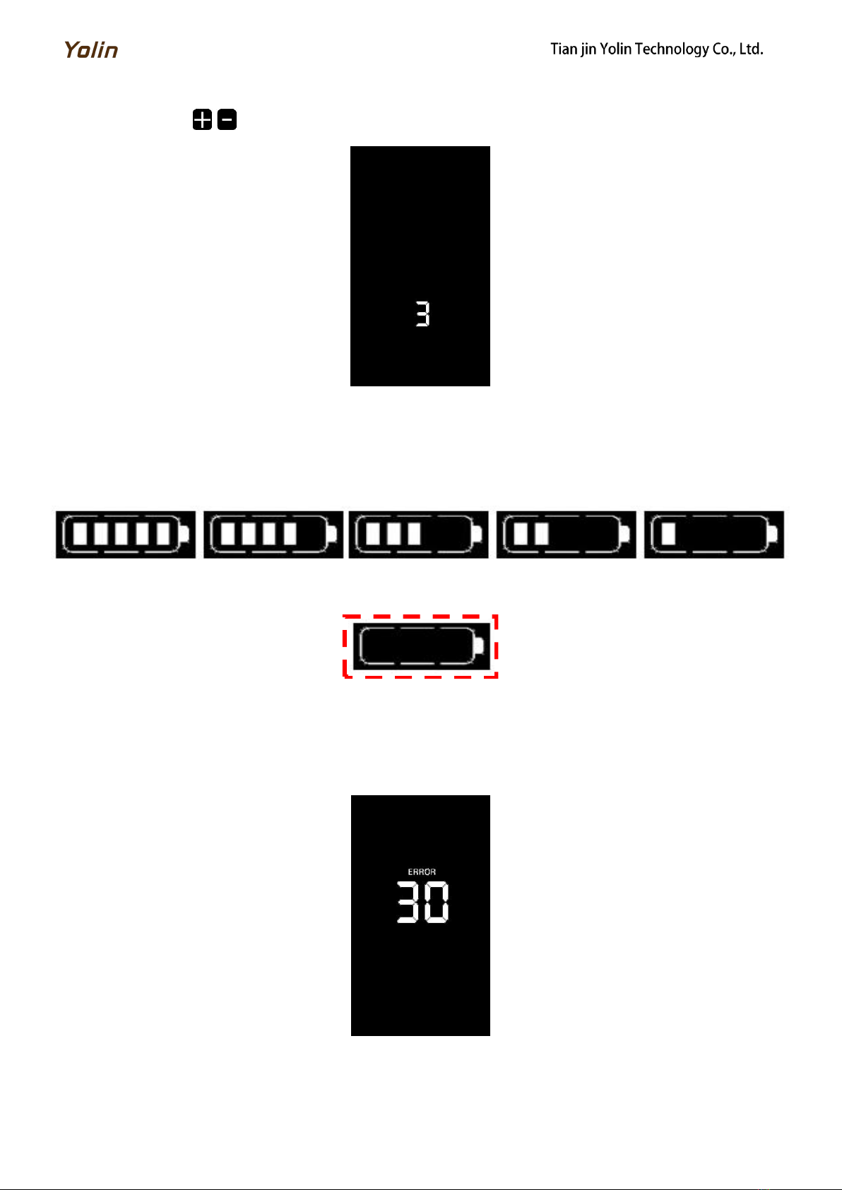
5.5 ASSIST LEVEL SELECTION ...................................................................................................................................................5
5.6 BATTERY LEVEL INDICATOR ............................................................................................................................................... 5
5.7 ERROR CODE INDICATOR ....................................................................................................................................................5
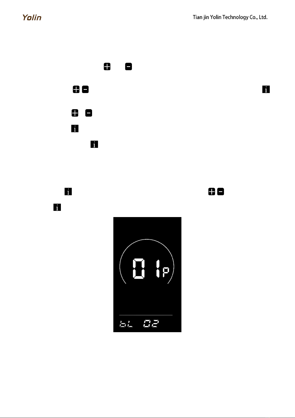
6. PERSONALIZED PARAMETER SETTINGS .................................................................................................................................... 6
7. SHORTCUT OPERATION ............................................................................................................................................................1
6.1 BACKLIGHT LUMINANCE SETTING ......................................................................................................................................6
6.2 METRIC/IMPERIAL SYSTEM SETTING ..................................................................................................................................7
6.3RATED VOLTAGE SETTING ................................................................................................................................................... 7
6.4AUTO SLEEP TIME SETTING .................................................................................................................................................. 8
6.5PAS LEVEL SETTING ........................................................................................................................................................... 8
6.6WHEEL DIAMETER SETTING .................................................................................................................................................9
6.7NUMBER OF SPEED SENSOR MAGNETS SETTING ................................................................................................................ 9
6.8SPEED LIMIT SETTING .......................................................................................................................................................10
6.9START-UP SETTING ............................................................................................................................................................ 10
6.10 DRIVE MODE SETTING ......................................................................................................................................................11
6.11 PEDAL ASSIST SENSITIVITY SETTING ..................................................................................................................................11
6.12 PEDAL ASSIST STRENGTH SETTING .......................................................................................................................................12
6.13NUMBER OF PEDAL ASSIST SENSOR MAGNETS SETTING .................................................................................................. 12
6.14CONTROLLER CURRENT LIMIT SETTING .........................................................................................................................13
6.15BATTERY UNDER VOLTAGE VALUE SETTING .....................................................................................................................13
6.16ODO RESETS SETTING .................................................................................................................................................... 14
6.17 CONTROLLER CRUISE CONTROL SETTING ...................................................................................................................................
6.18 6KM/H WALK BOOST SETTING .......................................................................................................................................... 14
6.19 POWER-ON PASSWORD SETTING (OPTION).................................................................................................................... 15
6
8. QUALITY COMMITMENTS AND WARRANTY SCOPE ................................................................................................................17
8.1 WARRANTY INFORMATION:.............................................................................................................................................. 17
8.2 NON-WARRANTY SCOPE .....................................................................................................................................................17

9. OUTGOING LINE CONNECTION DIAGRAM .............................................................................................................................. 18
9.1 WIRING SEQUENCE OF STANDARD CONNECTOR ............................................................................................................... 18
10. CONSIDERATIONS .................................................................................................................................................................
18SCHEDULE 1 ERROR CODE DEFINITIONS .......................................................................................................................
18SCHEDULE 2: ASSIST LEVEL RATIO DEFAULT VALUES ...............................................................................................
。

1
1. Product name and model
Intelligent LCD display for e-bike; model: YL80C.
2. Specifications
● 48V power supply
● Rated working current 15mA
● Maximum working current 30mA
● Leakage current at power-off <1uA
● Working current at the supply controller end 50mA
● Working temperature -20~60℃
● Storage temperature -30~70℃
3. Appearance and dimensions
Fig. 3-1 Picture of Display 80C
Fig. 3-2 Picture of Display 80C Buttons

2
Fig. 3-3 Front View of Display 80C Dimensions
Fig. 3-4 Side View of Display 80C Dimensions
4. Function overview and functional area layout
4.1 Function overview
Display YL80C provides a variety of functions to meet your riding needs, including:
● Battery level indicator
● Assist level adjustment and indication
● Speed indicator (including real-time speed, maximum speed and average speed)
● Distance indicator (including trip distance and ODO)
● Push assistance control and indication
● Headlight control and indication
● Error code indicator
● Custom parameter setting (e.g., wheel diameter, speed limit, assist level, power-on password,controller current limit,
etc.)
● Reset function
4.2 Functional area layout
Fig. 4-1 Functional Area Layout Interface of Display YL80C
Battery level indicator
Speed indicator
Fault indicator
Assist level indicator
Push assistance indicator
Numeric indicator
Headlight indicator
Speed unit indicator
Metric system: km/h
Imperial system: mile/h
Unit indicator
Trip distance indicator
ODO
Maximum speed indicator
Average speed indicator

3
4.3 Button definitions
There are five buttons on the operating unit of display YL80C, i.e., the on/off button , plus button , minus
button , headlight button and switching button .
5. General operation
5.1 Power on/off
By pressing and holding the button , the display will start to work and the working power supply of the controller
will be turned on. In the power-on state, by pressing the button , your e-bike will be powered off. In the power-off state,
the display will no longer use the battery power, and its leakage current will be less than 1uA.
■ If your e-bike is not used for more than 10 minutes, the display will be automatically powered off.
5.2 Display interface
After the display is turned on, the display will show the real-time speed (km/h) and the trip distance (km) by default.
By pressing the button , the information displayed will be switched between the trip distance (km), ODO (km),
maximum speed (km/h), average speed (km/h) and riding power.
Fig. 5-1 Display Interface Switching
Trip distance indicator
ODO
Maximum speed indicator
Average speed indicator

4
5.3 Push assistance
By pressing and holding the button , the electric push assistance mode will be enabled. Your e-bike will run at the
constant speed at the promoted speed. The display will show . By releasing the button , your e-bike will immediately
stop power output and return to the state before push assistance.
Fig. 5-2 Push Assistance Indicator Interface
■ The push assistance function can only be used when you are pushing your e-bike. Please do not use it during riding.
5.4 Headlight on/off
By pressing the button , the controller will turn on the headlights and the display backlight will turn dark; by
pressing the button again, the controller will turn off the headlights and the display backlight will resumes the
luminance.
Fig. 5-3 Backlight-on Indication Interface

5
5.5 Assist level selection
By pressing the button / , the e-bike assist level will be switched to change the motor output power.
Fig. 5-4 Assist Level Switching Interface
5.6 Battery level indicator
The battery level indicator consists of five segments. When the battery is fully charged, the five segments will be all on.
In case of undervoltage, the outline of the battery indicator will flash, which means the battery has to be charged
immediately.
Full battery level indication
4-segment indication
3-segment indication
2-segment indication
1-segment indication
Undervoltage flashing
Fig. 5-5 Battery Level Indicator Interface
5.7 Error code indicator
When a fault occurs in the electronic control system of your e-bike, the display will automatically indicate the error
code. Detailed definitions of error codes are shown in Schedule 1.
Fig. 5-6 Error Code Indicator Interface
■ When an error code appears on the display interface, please conduct troubleshooting in time. Otherwise, your e-bike will
not work normally.

6
6. Personalized parameter settings
■ All parameters can only be set when your e-bike stops.
The steps for general setting are as follows:
In the power-on state, when the display shows the speed of 0,
(1) (1) Press and hold the buttons and at the same time for more than 2 seconds to enter the personalized
parameter setting interface;
(2) Press the button / to switch the selection interface of general setting options, and press the button to
enter the parameter modification interface;
(3) Press the button / for parameter selection;
(4) Press the button to save the parameter and return to the selection interface of general setting options;
(5) Press and hold the button to save the parameter and exit the selection interface of general setting options.
6.1 Backlight luminance setting
01P refers to the backlight luminance setting option. Settable range is 0-3, which represent the backlight luminance, 1
for the minimum luminance, 2 for the standard luminance and 3 for the maximum luminance.
Press the button to enter the parameter modification interface. Press the button / for parameter selection.
Press the button to save the parameter and return to the selection interface of general setting options.
Fig. 6-1 Backlight Luminance Setting Interface

7
6.2 Metric/imperial system setting
02P refers to the metric/imperial system setting option. 01 represents the imperial system, and 00 represents the metric
system.
Press the button to enter the parameter modification interface. Press the button / for parameter selection.
Press the button to save the parameter and return to the selection interface of general setting options.
Fig. 6-2 Imperial System Setting Interface
Fig. 6-3 Metric System Setting Interface
6.3 Rated voltage setting
03P is the rated voltage setting. The available rated voltage range is: 24V、36V、48V、60V.
Press to enter the parameter changing state. Press the / to select the parameter and press to save the
parameter setting and return to the personalized parameter setting interface.
Figure 6-4 Rated voltage setting interface

8
6.4 Auto Sleep Time Setting
04P is the auto sleep time setting. To save the battery power and reach higher range, this display will be turned off after
it has not been used for a time. The adjustable range is: 1~60min, 00 means no auto shutdown. The factory default setting is
10 minutes.
Press to enter the parameter changing state. Press the / to select the parameter and press to save the
parameter setting and return to the personalized parameter setting interface.
Figure 6-5 Auto Power Off Time Setting Interface
6.5 PAS level setting
05P is the Pedal assist level setting. The available PAS level settings are: 0~3, 1~3, 0~5, 1~5.
Press to enter the parameter changing state. Press the / to select the parameter and press to save the
parameter setting and return to the personalized parameter setting interface.
Figure 6-6 PAS level setting interface

9
6.6 Wheel diameter setting
06P is the wheel diameter setting. The adjustable wheel diameter range is: 1~32inch.
Press to enter the parameter changing state. Press the / to select the parameter and press to save the
parameter setting and return to the personalized parameter setting interface.
Figure 6-7 Wheel diameter setting interface
6.7 Number of speed sensor magnets setting
07P is the speed sensor magnet number setting. The adjustable speed sensor magnet number range is: 1 ~ 255 pcs.
Press to enter the parameter changing state. Press the / to select the parameter and press to save the
parameter setting and return to the personalized parameter setting interface.
Figure 6-8 Number of speed sensor magnets setting interface

10
6.8 Speed Limit Setting
08P is the speed limit setting. The adjustable speed limit range is: 1~100km/h. (The maximum adjustable speed limit
varies by different protocols).
Press to enter the parameter changing state. Press the / to select the parameter and press to save the
parameter setting and return to the personalized parameter setting interface.
Figure 6-9 Speed limit setting interface
6.9 Start-up setting
09P is the start-up setting. The display can choose the following start modes: 00→zero start, 01→non-zero start.
Press to enter the parameter changing state. Press the / to select the parameter and press to save the
parameter setting and return to the personalized parameter setting interface.
Figure 6-10 Start-up setting interface

11
6.10 Drive mode setting
10P is the drive mode setting. The available drive modes are: 00→Pedal assist only, 01→Electric only, 02→Both Pedal
assist and electric.
Press to enter the parameter changing state. Press the / to select the parameter and press to save the
parameter setting and return to the personalized parameter setting interface.
Figure 6-11 Drive mode setting interface
6.11 Pedal assist sensitivity setting
11P is the pedal assist sensitivity setting. When set to higher numbers, it will take more crank rotations to activate the
motor. On lower numbers, it will take little crank rotation to activate the motor. The adjustable range is: 1~24.
Press to enter the parameter changing state. Press the / to select the parameter and press to save the
parameter setting and return to the personalized parameter setting interface.
Figure 6-12 Pedal assist sensitivity setting interface

12
6.12 Pedal assist strength setting
12P is the Pedal assist strength setting. The Pedal assist strength is the relative strength of the PWM signal from the
controller when start to activate pedal assist. The adjustable range is 0 ~ 5. 0 is the weakest strength and 5 is the strongest.
Press to enter the parameter changing state. Press the / to select the parameter and press to save the
parameter setting and return to the personalized parameter setting interface.
Figure 6-13 Pedal assist Start-up intensity setting interface
6.13 Number of pedal assist sensor magnets setting
13P is the number of pedal assist sensor magnets setting. The adjustable range: 5-12 pcs.
Press to enter the parameter changing state. Press the / to select the parameter and press to save the
parameter setting and return to the personalized parameter setting interface.
Figure 6-14 Number of pedal assist sensor magnets setting interface

13
6.14 Controller Current Limit Setting
14P is the controller current limit setting. The adjustable range is: 1~50A.
Press to enter the parameter changing state. Press the / to select the parameter and press to save the
parameter setting and return to the personalized parameter setting interface.
Figure 6-15 Controller current limit setting interface
6.15 Battery under voltage value setting
15P is the battery under voltage setting. The value can be adjusted based on the current rated voltage.
Press to enter the parameter changing state. Press the / to select the parameter and press to save the
parameter setting and return to the personalized parameter setting interface.
Figure 6-16 Battery under voltage value setting interface

14
6.16 ODO resets setting
16P is the ODO resets setting. The display can choose the following: 00→non reset, 01→reset.
Press to enter the parameter changing state. Press the / to select the parameter and press to save the
parameter setting and return to the personalized parameter setting interface.
Figure 6-17 ODO resets setting interface
6.18 6km/h walk boost setting
18P is the 6km/h walk boost setting. The display can choose the following: 00→turn off walk boost function, 01→turn
on walk boost function.
Press to enter the parameter changing state. Press the / to select the parameter and press to save the
parameter setting and return to the personalized parameter setting interface.
Figure 6-19 6km/h walk boost setting interface

15
6.19 Power-on password setting (option)
19P is the power-on password setting. The power-on password is not activated by default but users can activate it from
setting PSd-y. The factory default password is 1212. Users can set other four-digit password. Please keep the password in
mind after changing it, otherwise you will not be able to use the display.
Press to enter the parameter changing state. Press the / to select the parameter. PSd-y means the
power-on password is activated while PSd-n is off. Press to confirm the mode and enter the state of setting the four
digits power-on password or exit to the personalized parameter setting interface.

16
Figure 6-20 Power-on Password Activated interface Figure 6-21 Power-on Password OFF interface
In the password setting mode, the adjustable digit will flash. Press the / to select the parameter and press
to save the numbers and go to the next digit setting. Long press to save the parameter setting and return to the
personalized parameter setting interface after finish setting the four digits in turn.
Figure 6-22 Power-on password setting interface
7. Shortcut operation
7.1 Restore factory settings operation
dEF is the restore factory default parameter settings. dEF-Y is to restore default settings, and dEF-N is not to restore.
Enter into the main setting interface and keep the speed at 0, press and hold and simultaneously for 2s to
enter the restore factory default setting interface. Pressing / to toggle to dEF-Y. Then after pressing to
confirm, the display will show dEF-0 for a few seconds and then automatically start to restore the factory default settings.
The display will automatically exit to setting interface after the restoration.
Figure 7-1 Restore Factory Default Settings Interface

17
7.2 Trip odometer reset operation
The display can record trip odometer and odometer. Trip odometer is not automatically reset after turning off. The trip
odometer needs to be reset manually.
Enter into the main setting interface and keep the speed at 0, press and hold and simultaneously for 2s to
reset the trip odometer. The main interface will flash during the reset process.
Figure 7-2 Trip Odometer Reset Interface
8. Quality commitments and warranty scope
8.1 Warranty information:
● For the faults caused by the quality of the product under normal use, the Company will be responsible for providing
limited warranty during the warranty period.
● The warranty period of the product is within 12 months from delivery.
8.2 Non-warranty scope
● The enclosure is opened
● The connector is damaged
● The enclosure is scratched or damaged after delivery
● The outgoing line of the display is scratched or broken
● Faults or damage caused by force majeure (such as fires, earthquakes, etc.) or natural disasters (such as lightning
strikes, etc.)
● The warranty period has expired
Other manuals for YL80C
3
Table of contents
Other Yolin Bicycle Accessories manuals
Popular Bicycle Accessories manuals by other brands

Hamax
Hamax Universal Carrier adapter user manual

Cateye
Cateye Vectra CC-7000 instruction manual

SpeedFun
SpeedFun FURIOUS EVO Vers EASY+ instructions

eProdigy Bikes
eProdigy Bikes Banff Assembly guide

Bear Bones Systems
Bear Bones Systems Motono Dirt Bike Platform user manual

Urban Iki
Urban Iki Front seat Installation guides