York CZH User manual

835965-UIM-C-0814
R-410A
OUTDOOR SPLIT-SYSTEM
AIR CONDITIONING
MODELS: 18 SEER - CZH / AC8B / AL8B SERIES
MODELS: 16 SEER - CZF / AC6B / AL6B SERIES
2 TO 5 TONS
INSTALLATION MANUAL
®
TABLE OF CONTENTS
GENERAL . . . . . . . . . . . . . . . . . . . . . . . . . . . . . . . . . . . . . . . 1
SAFETY . . . . . . . . . . . . . . . . . . . . . . . . . . . . . . . . . . . . . . . . . 1
UNIT INSTALLATION . . . . . . . . . . . . . . . . . . . . . . . . . . . . . . 2
EVACUATION . . . . . . . . . . . . . . . . . . . . . . . . . . . . . . . . . . . . 5
ELECTRICAL CONNECTIONS . . . . . . . . . . . . . . . . . . . . . . . 5
SYSTEM CHARGE . . . . . . . . . . . . . . . . . . . . . . . . . . . . . . . 17
INSTRUCTING THE OWNER . . . . . . . . . . . . . . . . . . . . . . . 17
AC CONTROL BOARD FUNCTIONALITY . . . . . . . . . . . . . 18
WIRING DIAGRAM . . . . . . . . . . . . . . . . . . . . . . . . . . . . . . . 22
START UP SHEET . . . . . . . . . . . . . . . . . . . . . . . . . . . . . . . . 25
LIST OF FIGURES
Typical Installation with Required Clearances . . . . . . . . . . . . . . 3
Tubing Hanger . . . . . . . . .. . . . . . . . . . .. . . . . . . . . . .. . . . . . . . 4
Underground Installation . . . . . . . . . . . . . . . . . . . . . . . . . . . . . . . 4
Heat Protection . . . . . . . . . . . . . . . . . . . . . . . . . . . . . . . . . . . . 5
Typical Field Wiring . . . . . . . . . . . . . . . . . . . . . . . . . . . . . . . . . 6
Communications Harness Connection . . . . . . . . . . . . . . . . . . . 6
Communicating AC with Communicating
Air Handler or Furnace . . . . . . . . . . . . . . . . . . . . . . . . . . . . . . . 7
Communicating AC with Non-Communicating Air Handler
or Furnace using Communicating Interface Control . . . . . . . . . . 7
Thermostat Wiring – Single Stage Air Conditioner
(with AC control) – PSC Air Handler . . . . . . . . . . . . . . . . . . . . . . . 8
Thermostat Wiring – Single Stage Air Conditioner
(with AC control) – VS Air Handler . . . . . . . . . . . . . . . . . . . . . . . 9
Thermostat Wiring – Single Stage Air Conditioner
(with AC control) – Modulating Furnace . . . . . . . . . . . . . . . . . . . 10
Thermostat Chart - Two Stage AC –
Two Stage Variable Speed Furnaces . . . . . . . . . . . . . . . . . . . 11
Thermostat Chart - Two Stage AC –
Two Stage Variable Speed Furnaces . . . . . . . . . . . . . . . . . . . 12
Thermostat Chart - Two Stage AC –
Variable Speed Furnaces . . . . . . . . . . . . . . . . . . . . . . . . . . . . . 13
Thermostat Chart - Two Stage AC –
Variable Speed Furnaces . . . . . . . . . . . . . . . . . . . . . . . . . .. . . . 14
Thermostat Chart - Two Stage AC –
Variable Speed Furnaces . . . . . . . . . . . . . . . . . . . . . . . . . . . . 15
Thermostat Chart - Two Stage AC –
Variable Speed Furnaces . . . . . . . . . . . . . . . . . . . . . . . . . . . . 16
Single Stage Wiring Diagram (2 - 4 Ton) . . . . . . . . . . . . . . . . 22
Single Stage Wiring Diagram (5 Ton) . . . . . . . . . . . . . . . . . . . . 23
Two Stage Wiring Diagram . . . . . . . . . . . . . . . . . . . . . . . . . . . . 24
LIST OF TABLES
R-410A Saturation Properties . . . . . . . . . . . . . . . . . . . . . . . . 18
TEST Input Functionality . . . . . . . . . . . . . . . . . . . . . . . . . . . . 19
Operational Mode Display . . . . . . . . . . . . . . . . . . . . . . . . . . . 19
Status Code Display . . . . . . . . . . . . . . . . . . . . . . . . . . . . . . . 19
Operational Fault Codes . . . . . . . . . . . . . . . . . . . . . . . . . . . . 20
Sensor or Switch Fault Codes . . . . . . . . . . . . . . . . . . . . . . . 20
Wiring Related Fault Codes . . . . . . . . . . . . . . . . . . . . . . . . . 20
SECTION I: GENERAL
The outdoor units are designed to be connected to a matching indoor
coil with sweat connect lines. Sweat connect units are factory charged
with refrigerant for the highest sales volume evaporator plus 15 feet of
field supplied lines.
Matching indoor coils require a thermal expansion valve. The refriger-
ant charge may need to be changed for some system combinations,
elevation differences, or total line lengths. See tabular data sheet pro-
vided in unit literature packet for charge requirements. Refer to Applica-
tion Data covering “General Piping Recommendations and Refrigerant
Line Length” (Part Number 247077).
SECTION II: SAFETY
This is a safety alert symbol. When you see this symbol on
labels or in manuals, be alert to the potential for personal
injury.
Understand and pay particular attention to the signal words DANGER,
WARNING, or CAUTION.
DANGER indicates an imminently hazardous situation, which, if not
avoided, will result in death or serious injury.
WARNING indicates a potentially hazardous situation, which, if not
avoided, could result in death or serious injury.
CAUTION indicates a potentially hazardous situation, which, if not
avoided may result in minor or moderate injury. It is also used to
alert against unsafe practices and hazards involving only property dam-
age.

835965-UIM-C-0814
2Johnson Controls Unitary Products
INSPECTION
As soon as a unit is received, it should be inspected for possible dam-
age during transit. If damage is evident, the extent of the damage
should be noted on the carrier’s delivery receipt. A separate request for
inspection by the carrier’s agent should be made in writing. See Local
Distributor for more information.
Requirements For Installing/Servicing R-410A Equipment
• Gauge sets, hoses, refrigerant containers, and recovery systems
must be designed to handle the POE type oils and the higher
pressures of R-410A.
• Manifold sets should be 800 PSIG high side and 250 PSIG low
side with 550 PSIG low side retard.
• All hoses must have a 700 PSIG service pressure rating.
• Leak detectors should be designed to detect HFC refrigerant.
• Recovery equipment (including refrigerant recovery containers)
must be specifically designed to handle R-410A.
• Do not use an R-22 TXV.
• A liquid-line filter drier is required on every unit.
LIMITATIONS
The unit should be installed in accordance with all National, State, and
Local Safety Codes and the limitations listed below:
1. Limitations for the indoor unit, coil, and appropriate accessories
must also be observed.
2. Only variable speed air handlers or variable speed furnaces should
be used with these models.
3. The outdoor unit must not be installed with any duct work in the air
stream. The outdoor fan is the propeller type and is not designed to
operate against any additional external static pressure.
4. The maximum and minimum conditions for operation must be
observed to ensure a system that will give maximum performance
with minimum service.
5. For 16 SEER models only, the unit should not be operated at out-
door temperatures below 65° F without an approved low ambient
operation accessory kit installed.
6. The maximum allowable line length for this product is 75 feet.
SECTION III: UNIT INSTALLATION
LOCATION
Before starting the installation, select and check the suitability of the
location for both the indoor and outdoor unit. Observe all limitations and
clearance requirements.
The outdoor unit must have sufficient clearance for air entrance to the
condenser coil, for air discharge, and for service access. See Figure 1
"Typical Installation with Required Clearances".
If the unit is to be installed on a hot sun exposed roof or a paved
ground area that is seasonally hot, the unit should be raised sufficiently
above the roof or ground to avoid taking the accumulated layer of hot
air into the outdoor unit.
Provide adequate structural support.
ADD-ON REPLACEMENT/RETROFIT
When this unit is being used as a replacement for an R-22 unit, it is
required that the outdoor unit, indoor coil, and metering device all be
replaced. Line-set change out is also recommended. The following
steps should be performed in order to insure proper system operation
and performance.
1. Change-out of the indoor coil to an approved R-410A coil with the
appropriate metering device.
2. Change-out of the line-set when replacing an R-22 unit with an
R-410A unit is highly recommended to reduce cross-contamination
of oils and refrigerants.
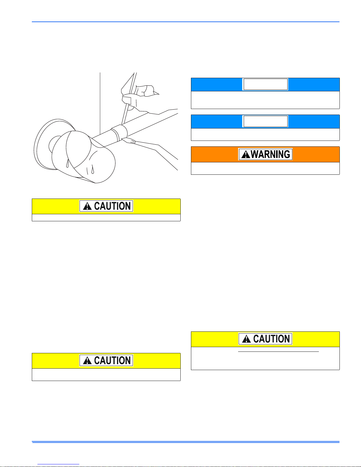
3. If change-out of the line set is not practical, then the following pre-
cautions should be taken.
• Inspect the line set for kinks, sharp bends, or other restrictions,
and for corrosion.
• Determine if there are any low spots which might be serving as oil
traps.
• Flush the line set with a commercially available flush kit to
remove as much of the existing oil and contaminants as possible.
• Install a suction line filter-drier to trap any remaining contami-
nants, and remove after 50 hours of operation.
4. If the outdoor unit is being replaced due to a compressor burnout,
then installation of a 100% activated alumina suction-line filter drier
is required, in addition to the factory installed liquid-line drier. Oper-
ate the system for 10 hours. Monitor the suction drier pressure drop.
If the pressure drop exceeds 3 psig, replace both the suction-line
and liquid-line driers. After a total of 10 hours run time where the
suction-line pressure drop has not exceeded 3 psig, replace the liq-
uid line drier, and remove the suction-line drier. Never leave a suc-
tion-line drier in the system longer than 50 hours of run time.
Improper installation may create a condition where the operation of
the product could cause personal injury or property damage.
Improper installation, adjustment, alteration, service, or mainte-
nance can cause injury or property damage. Refer to this manual
for assistance or for additional information, consult a qualified con-
tractor, installer, or service agency.
This product must be installed in strict compliance with the
enclosed installation instructions and any applicable local, state,
and national codes including, but not limited to building, electrical,
and mechanical codes.
R-410A systems operate at higher pressures than R-22 systems.
Do not use R-22 service equipment or components on R-410A
equipment. Service equipment Must Be Rated for R-410A.
For multiple unit installations, units must be spaced a minimum of
24 inches apart (coil face to coil face).
NOTICE

835965-UIM-C-0814
Johnson Controls Unitary Products 3
GROUND INSTALLATION
The unit may be installed at ground level on a solid base that will not
shift or settle, causing strain on the refrigerant lines and possible leaks.
Maintain the clearances shown in Figure 1 "Typical Installation with
Required Clearances" and install the unit in a level position.
Normal operating sound levels may be objectionable if the unit is placed
directly under windows of certain rooms (bedrooms, study, etc.).
Isolate the unit from rain gutters to avoid any possible wash out of the
foundation.
ROOF INSTALLATION
When installing units on a roof, the structure must be capable of sup-
porting the total weight of the unit, including a pad, lintel, rails, etc.,
which should be used to minimize the transmission of sound or vibra-
tion into the conditioned space.
WALL MOUNT INSTALLATION
Care must be taken to mount the outdoor unit on a solid base that is
sloped to shed water, secure from settlement, and is isolated from the
structural foundation or walls to prevent sound and vibration transmis-
sion into the living space. In addition heat pump units must be elevated
above anticipated snow accumulation levels to allow for proper defrost
drainage and airflow.
On occasion, site conditions may require direct wall mounted brackets
to be used to locate and support the outdoor unit. In these applications,
care must be taken to address unit base pan support, structural integ-
rity, safe access and servicability, as well as the possible sound and
vibration transmission into the structure. These applications are best
served by a properly engineered solution.
UNIT PLACEMENT
1. Provide a base in the pre-determined location.
2. Remove the shipping carton and inspect for possible damage.
3. Compressor tie-down bolts should remain tightened.
4. Position the unit on the base provided.
LIQUID LINE FILTER-DRIER
The air conditioning unit’s copper spun filter/dryer is located on the liq-
uid line.
TXV INSTALLATIONS
The following are the basic steps for installation. For detailed instruc-
tions, refer to the Installation Instructions accompanying the TXV kit.
Install TXV kit as follows:
1. Relieve the holding charge from the indoor coil by depressing the
Schrader valve stem located in the end of the suction line. Cut the
spundown copper to allow installation of the suction line.
2. After holding charge is completely discharged, loosen and remove
the schraeder cap seal.
3. Loosen and remove distributor cap seal.
4. Install the thermal expansion valve to the distributor assembly with
supplied fittings. Hand tighten and turn an additional 1/4 turn to
seal. Do not overtighten fittings.
5. Install the liquid line to the top of the thermal expansion valve with fit-
ting supplied with the liquid line. Hand modify the liquid line to align
with casing opening. Hand tighten the liquid line and an additional
1/4 turn to seal.
6. Install the TXV equalizer line into the vapor line as follows:
a. Hand tighten the 1/4” SAE nut to the schraeder fitting and an
additional 1/3 turn to seal.
7. At this time do not attach sensing bulb. This will be covered later
after brazing of the lines.
FIGURE 1: Typical Installation with Required Clearances
THERMOSTAT
NEC CLASS 1
WIRING
TO INDOOR
BLOWER NEC CLASS 2
WIRING
TO COIL
WEATHERPROOF
DISCONNECT
SWITCH
24” SERVICE
ACCESS
CLEARANCE
NOTE: ALL OUTDOOR WIRING
MUST BE WEATHERPROOF
SEAL OPENINGS WITH
PERMAGUM OR EQUIVALENT
10” COIL
CLEARANCE AREA
60” OVERHEAD
CLEARANCE
A0202-001
Replacements for the liquid line drier must be exactly the same as
marked on the original factory drier. See Source 1 for O.E.M.
replacement driers.
Failure to do so or using a substitute drier or a granular type may
result in damage to the equipment.
Filter-Drier Source 1 Part No. Apply with Models
S1-02922195000 All
NOTICE

835965-UIM-C-0814
4Johnson Controls Unitary Products
PIPING CONNECTIONS
The outdoor condensing unit must be connected to the indoor evapora-
tor coil using field supplied refrigerant grade copper tubing that is inter-
nally clean and dry. Units should be installed only with the tubing sizes
for approved system combinations as specified in tabular data sheet.
The charge given is applicable for total tubing lengths up to 15 feet. See
Application Data Part Number 247077 for installing tubing of longer
lengths and elevation differences.
PRECAUTIONS DURING LINE INSTALLATION
1. Install the lines with as few bends as possible. Care must be taken
not to damage the couplings or kink the tubing. Use clean hard
drawn copper tubing where no appreciable amount of bending
around obstruction is necessary. If soft copper must be used, care
must be taken to avoid sharp bends which may cause a restriction.
2. The lines should be installed so that they will not obstruct service
access to the coil, air handling system, or filter.
3. Care must also be taken to isolate the refrigerant lines to minimize
noise transmission from the equipment to the structure.
4. The vapor line must be insulated with a minimum of 1/2" foam rubber
insulation (Armaflex or equivalent). Liquid lines that will be exposed
to direct sunlight and/or high temperatures must also be insulated.
5. Tape and suspend the refrigerant lines as shown. DO NOT allow
tube metal-to-metal contact. See Figure 2 "Tubing Hanger".
6. Use PVC piping as a conduit for all underground installations as
shown in Figure 3 "Underground Installation". Buried lines should be
kept as short as possible to minimize the build up of liquid refrigerant
in the vapor line during long periods of shutdown
7. Pack fiberglass insulation and a sealing material such as permagum
around refrigerant lines where they penetrate a wall to reduce vibra-
tion and to retain some flexibility.
8. See application part number 247077 for additional piping informa-
tion.
PRECAUTIONS DURING BRAZING OF LINES
All outdoor unit and evaporator coil connections are copper-to-copper
and should be brazed with a phosphorous-copper alloy material such
as Silfos-5 or equivalent. DO NOT use soft solder. The outdoor units
have reusable service valves on both the liquid and vapor connections.
The total system refrigerant charge is retained within the outdoor unit
during shipping and installation. The reusable service valves are pro-
vided to evacuate and charge per this instruction.
Serious service problems can be avoided by taking adequate precau-
tions to ensure an internally clean and dry system.
PRECAUTIONS DURING BRAZING SERVICE VALVE
Precautions should be taken to prevent heat damage to service valves
by wrapping a wet rag around it as shown in Figure 4 "Heat Protection".
Also, protect all painted surfaces, insulation, and plastic base during
brazing. After brazing, cool joint with wet rag.
The valve can be opened by removing the plunger cap and fully insert-
ing a hex wrench into the stem and backing out counter-clockwise until
valve stem just touches the chamfered retaining wall.
Connect the refrigerant lines using the following procedure:
1. Refer to the Tabular Data Sheet for proper vapor and liquid line siz-
ing.
2. Remove the cap and Schrader core from both the liquid and vapor
service valve service ports at the outdoor unit. Connect low pressure
nitrogen to the liquid line service port.
This system uses R-410A refrigerant which operates at higher pres-
sures than R-22. No other refrigerant may be used in this system.
Gauge sets, hoses, refrigerant containers, and recovery systems
must be designed to handle R-410A. If you are unsure, consult the
equipment manufacturer.
Never install a suction-line filter drier in the liquid line of an R-410A
system. Failure to follow this warning can cause a fire, injury or
death.
Using a larger than specified line size could result in oil return prob-
lems. Using too small a line will result in loss of capacity and other
problems caused by insufficient refrigerant flow. Slope horizontal
vapor lines at least 1" every 20 feet toward the outdoor unit to facili-
tate proper oil return.
FIGURE 2: Tubing Hanger
NOTICE
A0151-001
SHEET METAL HANGER
LIQUID
LINE
INCORRECT
CORRECT
INSULATED VAPOR LINE
TAPE
FIGURE 3: Underground Installation
Dry nitrogen should always be supplied through the tubing while it
is being brazed, because the temperature is high enough to cause
oxidation of the copper unless an inert atmosphere is provided. The
flow of dry nitrogen should continue until the joint has cooled.
Always use a pressure regulator and safety valve to insure that only
low pressure dry nitrogen is introduced into the tubing. Only a small
flow is necessary to displace air and prevent oxidation.
This is not a backseating valve. The service access port has a
valve core. Opening or closing valve does not close service access
port.
If the valve stem is backed out past the chamfered retaining wall,
the O-ring can be damaged causing leakage or system pressure
could force the valve stem out of the valve body possibly causing
personal injury.
Do not leave the system open to the atmosphere. Unit damage
could occur due to moisture being absorbed by the POE oil in the
system. This type of oil is highly susceptible to moisture absorp-
tion.
TO INDOOR COIL
TO
O
UT
DO
OR
U
NI
T
LIQUID LIN
E
CAP
PVC
COND
U
IT
IN
SULA
TE
D
VAPOR LINE
A0152-001

835965-UIM-C-0814
Johnson Controls Unitary Products 5
3. Braze the liquid line to the liquid valve at the outdoor unit. Be sure to
wrap the valve body with a wet rag. Allow the nitrogen to continue
flowing.
4. Relieve the holding charge from the indoor coil by depressing the
Schrader valve stem located in the end of the suction line. Cut the
spundown copper to allow installation of the suction line.
5. If TXV has not been installed refer to Page 3 “TXV INSTALLA-
TIONS”.
6. Braze the liquid line to the evaporator liquid connection. Nitrogen
should be flowing through the evaporator coil.
7. Slide the grommet away from the vapor connection at the indoor coil.
Braze the vapor line to the evaporator vapor connection. After the
connection has cooled, slide the grommet back into original position.
a. Install the TXV bulb to the vapor line near the equalizer line, using
the bulb clamp(s) furnished with the TXV assembly. Ensure the
bulb is making maximum contact. For detailed instructions, refer
to the Installation Instructions accompanying the TXV kit.
b. Bulb should be installed on a horizontal run of the vapor line if
possible. The bulb should be installed on top of the line.
c. If bulb installation is made on a vertical run, the bulb should be
located at least 16 inches from any bend, and on the tubing sides
opposite the plane of the bend. The bulb should be positioned
with the bulb tail at the top, so that the bulb acts as a reservoir.
d. Bulb should be insulated using thermal insulation provided to pro-
tect it from the effect of the surrounding ambient temperature.
Cover completely to insulate from air-stream.
8. Protect the vapor valve with a wet rag and braze the vapor line con-
nection to the outdoor unit. The nitrogen flow should be exiting the
system from the vapor service port connection. After this connection
has cooled, remove the nitrogen source from the liquid fitting service
port.
9. Replace the Schrader core in the liquid and vapor valves.
10.Leak test all refrigerant piping connections.
SECTION IV: EVACUATION
1. It will be necessary to evacuate the system to 500 microns or less. If
a leak is suspected, leak test with dry nitrogen to locate the leak.
Repair the leak and test again.
To verify that the system has no leaks, simply close the valve to the
vacuum pump suction to isolate the pump and hold the system
under vacuum. Watch the micron gauge for a few minutes. If the
micron gauge indicates a steady and continuous rise, it’s an indica-
tion of a leak. If the gauge shows a rise, then levels off after a few
minutes and remains fairly constant, it’s an indication that the system
is leak free but still contains moisture and may require further evacu-
ation if the reading is above 500 microns.
2. While system is being evacuated proceed to SECTION V ”ELEC-
TRICAL CONNECTIONS”. System charging will be covered under
SECTION VI ”SYSTEM CHARGE”
SECTION V: ELECTRICAL CONNECTIONS
GENERAL INFORMATION & GROUNDING
Check the electrical supply to be sure that it meets the values specified
on the unit nameplate and wiring label.
Power wiring, control (low voltage) wiring, disconnect switches, and
over current protection must be supplied by the installer. Wire size
should be sized per NEC requirements.
The complete connection diagram and schematic wiring label is located
on the inside surface of the unit service access panel.
FIGURE 4: Heat Protection
The evaporator is pressurized.
In all cases, mount the TXV bulb after vapor line is brazed and has
had sufficient time to cool.
A0153-001
Line set and indoor coil can be pressurized to 250 psig with dry
nitrogen and leak tested with a bubble type leak detector. Then
release the nitrogen charge.
Do not use the system refrigerant in the outdoor unit to purge or
leak test.
Never attempt to repair any brazed connections while the system is
under pressure. Personal injury could result.
All field wiring must USE COPPER CONDUCTORS ONLY and be
in accordance with Local, National, Fire, Safety, & Electrical Codes.
This unit must be grounded with a separate ground wire in accor-
dance with the above codes.
NOTICE
NOTICE

835965-UIM-C-0814
6Johnson Controls Unitary Products
FIELD CONNECTIONS POWER WIRING
1. Install the proper size weatherproof disconnect switch outdoors and
within sight of the unit.
2. Remove the screws at the bottom of the corner cover. Slide corner
cover down and remove from unit. See Figure 5 "Typical Field Wir-
ing".
3. Run power wiring from the disconnect switch to the unit.
4. Remove the service access panel to gain access to the unit wiring.
Route wires from disconnect through power wiring opening provided
and into the unit control box.
5. Install the proper size time-delay fuses or circuit breaker, and make
the power supply connections.
FIELD CONNECTIONS CONTROL WIRING
(CONVENTIONAL)
1. Route low voltage wiring into bottom of control box. Make low volt-
age wiring connections inside the junction box per Figures 9-11
“Thermostat Wiring”.
2. The complete connection diagram and schematic wiring label is
located on the inside surface of the unit service access panel.
3. Replace the corner cover and service access panel that were
removed in Steps 2 and 4 of the ”FIELD CONNECTIONS POWER
WIRING” section.
4. All field wiring to be in accordance with national electrical codes
(NEC) and/or local-city codes.
5. Mount the thermostat about 5 ft. above the floor, where it will be
exposed to normal room air circulation. Do not place it on an outside
wall or where it is exposed to the radiant effect from exposed glass
or appliances, drafts from outside doors, or supply air grilles.
6. Route the 24-volt control wiring (NEC Class 2) from the outdoor unit
to the indoor unit and thermostat.
FIELD CONNECTIONS CONTROL WIRING
(SERIAL COMMUNICATION)
1. The Communications Harness is provided with the Touch Screen
Communicating Control.
2. Route low voltage four conductor shielded thermostat communica-
tions harness into junction box and connect to communications port
on control board. See Figure 6 "Communications Harness Connec-
tion".
3. Route low voltage wiring into bottom of control box. Make low volt-
age wiring connections inside the junction box per Figures 7-8.
4. The complete connection diagram and schematic wiring label is
located on the inside surface of the unit service access panel.
5. Replace the corner cover and service access panel that were
removed in Steps 2 and 4 of the “Field Connections Power Wiring”
section.
6. Mount the thermostat about 5 ft. above the floor, where it will be
exposed to normal room air circulation. Do not place it on an outside
wall or where it is exposed to the radiant effect from exposed glass
or appliances, drafts from outside doors, or supply air grilles.
7. Route the 24-volt control wiring (NEC Class 2) from the outdoor unit
to the indoor unit and thermostat.
FIGURE 5: Typical Field Wiring
Ambient temperature sensor should extend below corner cover by
1”.
Corner
Cover
Control
Wiring
Power
Wiring
Service
Access
Panel
Ambient
Temperature
Sensor A0203-001
NOTICE
To eliminate erratic operation, seal the hole in the wall at the ther-
mostat with permagum or equivalent to prevent air drafts affecting
the operation of the thermostat.
If unit is going to be setup as a communicating system, the conven-
tional wiring must be removed from the Outdoor Control Board, if
not, damage to control board or indoor control could occur.
FIGURE 6: Communications Harness Connection
Ambient temperature sensor should extend below corner cover by
1”.
To eliminate erratic operation, seal the hole in the wall at the ther-
mostat with Pergamum or equivalent to prevent air drafts affecting
the operation of the thermostat.
NOTICE
COMMUNICATIONS PORT CONTROL BOARD
COMMUNICATIONS
HARNESS
JUNCTION
BOX
A0204-001
NOTICE
NOTICE

835965-UIM-C-0814
Johnson Controls Unitary Products 7
DEHUMIDIFICATION CONTROL
A dehumidification control accessory 2HU06700124 may be used with
variable speed air handlers or furnaces in high humidity areas. This
control works with the variable speed indoor unit to provide cooling at a
reduced air flow, lowering evaporator temperature and increasing latent
capacity. The humidistat in this control opens the humidistat contacts on
humidity rise. To install, refer to instructions packaged with the acces-
sory and Figures 7-8. Prior to the installation of the dehumidification
control, the jumper across the HUMIDISTAT terminals on the indoor
variable speed air handler or furnace CFM selection board must be
removed.
During cooling, if the relative humidity in the space is higher than the
desired set point of the dehumidification control, the variable speed
blower motor will operate at lower speed until the dehumidification con-
trol is satisfied. A 40-60% relative humidity level is recommended to
achieve optimum comfort.
If a dehumidification control is installed, it is recommended that a mini-
mum air flow of 325 cfm/ton be supplied at all times.
INDOOR CFM CONFIGURATION
For proper system operation the indoor CFM must be set properly.
Refer to the Technical Guide for the outdoor unit for the recommended
air flow settings for each size condensing unit and matching indoor unit.
Set the cooling speed per the instructions for the air handler or furnace.
Verify the airflow.
If installed as a communicating system (outdoor, indoor, and thermo-
stat), the system will automatically adjust to the optimal airflow settings.
These parameters can also be modified using the Touch Screen Com-
municating Control. Refer to the Touch Screen Communicating Control
owner’s manual for this procedure. Manual setting of the airflow on the
ID equipment is not necessary with the Touch Screen Communicating
Control.
FIGURE 7: Communicating AC with Communicating Air Handler or
Furnace
R
C
Y1
Y2
Touch Screen
Communicating
Control
Air Handler/Furnace
Communicating
Control
Air Conditioner
Communicating
Control
GND
or C
GND
or C
B-
R
A+
GND
or C
GND
or C
B-
R
A+
GND
or C
GND
or C
B-
R
A+
A0205-001
FIGURE 8: Communicating AC with Non-Communicating Air Handler
or Furnace using Communicating Interface Control
R
C
Y1
Y2
HUM
W2
DHUM
W
G
C
R
O
Y
Y2
HUM
W2
DHUM
W
G
C
R
O
Y
Y2
Touch Screen
Communicating
Control
Communicating
Indoor
Interface Control
Non-Communicating
Indoor Unit
Air Conditioner
Communicating
Control
Wire per
non-comm.
installation
manual
Assume that
connections
are from
thermostat
GND
or C
GND
or C
B-
R
A+
GND
or C
GND
or C
B-
R
A+
GND
or C
GND
or C
B-
R
A+
A0206-001

835965-UIM-C-0814
8Johnson Controls Unitary Products
For additional connection diagrams for all UPG equipment refer to “Low Voltage System Wiring” document available online at www.upgnet.com in the
Product Catalog Section.
FIGURE 9: Thermostat Wiring – Single Stage Air Conditioner (with AC control) – PSC Air Handler
– PSC Air HandlerSingle Stage Air Conditioner (with AC control)
ID MODELS
Jumper 1 must be set
to “GAS/ELEC”
Y1
First Stage
Compressor
W2
Second Stage Heat
G
Fan
S1-THSU21P1b
THERMOSTAT
R
24 – Volt Hot
W1/O/B
First Stage Heat
C
24 – Volt Common
Jumper 3 must be set
to “ELEC”
SINGLE STAGE
AIR
CONDITIONER
C
24 – Volt Common
R
24 – Volt Hot
Y1
First Stage Compressor
Y2
Second Stage
Compressor
SINGLE STAGE
AIR CONDITIONER
External Humidistat
(Optional)
Open on Humidity Rise
Y1
First
Stage Compressor
COM
24 – Volt Common
R
24 – Volt Hot
G
Fan
W2
Second Stage Heat
O
Reversing Valve
Energized in Cool
X/L
Malfunction Light
HUM
Humidity Switch
Open on Humidity Rise
PSC
AIR HANDLER
CONTROL
Y/Y2
Second or Full
Stage Compressor
W1
First Stage Heat
EAC
(24 VAC out)
Electronic Air Cleaner
HUM OUT
(24 VAC out)
Humidifier
PSC
AIR HANDLER
Move HUM STAT
jumper to “YES”
if humidistat is to be
used.
Refer to AH
documentation
for W1 and W2 electric
heat staging options.
24VAC Humidifier
(Optional)
24VAC
Electronic Air Cleaner
(Optional)
A0207-002
Relay
Relay
MA
AHR

835965-UIM-C-0814
Johnson Controls Unitary Products 9
FIGURE 10: Thermostat Wiring – Single Stage Air Conditioner (with AC control) – VS Air Handler
V/S Air HandlerSingle Stage Air Conditioner (with AC control) -
ID MODELS
Jumper 1 must be set
to “GAS/ELEC”
Y1
First Stage
Compressor
W2
Second Stage Heat
G
Fan
S1-THSU21P1b
THERMOSTAT
R
24 – Volt Hot
W1/O/B
First Stage Heat
C
24 – Volt Common
Jumper 3 must be set
to “ELEC”
SINGLE STAGE
AIR
CONDITIONER
C
24 – Volt Common
R
24 – Volt Hot
Y1
First Stage Compressor
Y2
Second Stage
Compressor
SINGLE STAGE
AIR CONDITIONER
External Humidistat
(Optional)
Open on Humidity Rise
(Optional)
24VAC
Electronic Air Cleaner
(Optional)
Y1
First
Stage Compressor
COM
24 – Volt Common
R
24 – Volt Hot
G
Fan
W2
Second Stage Heat
O
Reversing Valve
Energized in Cool
X/L
Malfunction Light
HUM
Humidity Switch
Open on Humidity Rise
VARIABLE SPEED
AIR HANDLER
CONTROL
Y/Y2
Second or Full
Stage Compressor
W1
First Stage Heat
EAC
(24 VAC out)
Electronic Air Cleaner
HUM OUT
(24 VAC out)
VARIABLE
SPEED
AIR HANDLER
Move the HUM STAT
jumper to “YES”
if humidistat is to be
used.
Refer to AH
documentation
for W1 and W2 electric
heat staging options.
Relay
Relay
A0208-002
MV
AHV

835965-UIM-C-0814
10 Johnson Controls Unitary Products
FIGURE 11: Thermostat Wiring – Single Stage Air Conditioner (with AC control) – Modulating Furnace
– Modulating Furnace
Single Stage Air Conditioner (with AC control)
(Y,L,C)*(8,L)C
T*(8,L)C
T*9C
(Y,L,C)*9C
ID MODELS
Jumper 1 must be set
to “GAS/ELEC”
Y1
First Stage
Compressor
W2
Second Stage Heat
G
Fan
S1-THSU21P1b
THERMOSTAT
R
24 – Volt Hot
W1/O/B
First Stage Heat
C
24 – Volt Common
Jumper 3 must be set
to “GAS”
SINGLE STAGE
AIR
CONDITIONER
C
24 – Volt Common
R
24 – Volt Hot
Y1
First Stage Compressor
Y2
Second Stage
Compressor
SINGLE STAGE
AIR CONDITIONER
External Humidistat
(Optional)
Open on Humidity Rise
C
24 – Volt Common
R
24 – Volt Hot
Y1
First Stage Compressor
MODULATING
FURNACE CONTROL
G
Fan
MODULATING
FURNACE
Y/Y2
Second or Full
Stage Compressor
DHUM
Dehumidification-
Open on Humidity Rise
W
Modulating Heat
Move HUMIDISTAT
jumper to “YES”
if humidistat is to be used.
LO COMP
Single Stage
Compressor (OUT)
O
Reversing Valve
Energized in Cool
HI COMP
Second Stage
Compressor (OUT)
HEATPUMP jumper must
be set to “NO”
A0209-002

835965-UIM-C-0814
Johnson Controls Unitary Products 11
FIGURE 12: Thermostat Chart - Two Stage AC – Two Stage Variable Speed Furnaces
24VAC Humidifier
(Optional)
External Humidistat
(Optional)
Open on Humidity Rise
C
24 – Volt Common
Y
First Stage Compressor
Y2
Second Stage
Compressor
G
Fan
*PP32U70124
THERMOSTAT
W2
Second Stage Heat
R
24 – Volt Hot
(Heat XFMR)
RC
24 – Volt Hot
(Cool XFMR)
C
24 – Volt Common
Y
First Stage Compressor
Y2
Second Stage
Compressor
G
Fan
*DN22U00124
THERMOSTAT
W2
Second Stage Heat
R
24 – Volt Hot
(Heat XFMR)
RC
24 – Volt Hot
(Cool XFMR)
W
First Stage Heat
W
First Stage Heat
TWO STAGE
AIR
CONDITIONER
C
24 – Volt Common
R
24 – Volt Hot
Y1
First Stage Compressor
Y2
Second Stage
Compressor
Connection of the “C”
terminal, 24-Volt common
is optional when used with
batteries
Thermostat Installer Setup
0170-System Type-must
be set to 8-2 Heat/2 Cool
Multistage Conventional
Connection of the “C”
terminal, 24-volt common
is optional when used with
batteries
Thermostat Installer Setup
1-System Type-must
be set to 6-2 Heat/2 Cool
Multistage Conventional
Thermostat Installer Setup
15-Compressor Protection
-must be set to 5
C
24 – Volt Common
R
24 – Volt Hot
Y1
Single Stage
Compressor
TWO STAGE
VARIABLE SPEED
FURNACE CONTROL
G
Fan
TWO STAGE
VARIABLE SPEED
FURNACE
W/W1
First Stage Heat
Y/Y2
Second or Full
Stage Compressor
W2
Second Stage Heat
O
Reversing Valve
X/L
Malfunction Light
DHUM
Dehumidification
Move DHUM
jumper to “YES”
if humidistat is to be used.
ID MODELS
AC 24A Two Stage Air Conditioner – Two Stage Variable Speed Furnace
External Humidistat
(Optional)
Open on Humidity Rise
Relay
A0210-002
TM8V
TM9V

835965-UIM-C-0814
12 Johnson Controls Unitary Products
FIGURE 13: Thermostat Chart - Two Stage AC – Two Stage Variable Speed Furnaces
AC 24B Two Stage Air Conditioner – Two Stage Variable Speed Furnace
Connection of the “C”
Terminal, 24-Volt
Common, is optional when
used with batteries
C
24 – Volt Common
R
24 – Volt Hot
Y1
Single Stage
Compressor
TWO STAGE
VARIABLE SPEED
FURNACE CONTROL
G
Fan
TWO STAGE
VARIABLE SPEED
FURNACE
W/W1
First Stage Heat
Y/Y2
Second or Full
Stage Compressor
W2
Second Stage Heat
O
Reversing Valve
X/L
Malfunction Light
DHUM
Dehumidification
Move DHUM
jumper to “YES”
if humidistat is to be used.
ID MODELS
TWO STAGE
AIR
CONDITIONER
C
24 – Volt Common
R
24 – Volt Hot
Y1
First Stage Compressor
Y2
Second Stage
Compressor
24VAC Humidifier
(Optional)
External Humidistat
(Optional)
Open on Humidity Rise
C
24 – Volt Common
R
24 – Volt Hot
Y
First Stage Compressor
Y2
Second Stage
Compressor
G
Fan
*DN22C00124
THERMOSTAT
W2
Second Stage Heat
C
24 – Volt Common
R
24 – Volt Hot
Y1
First Stage Compressor
Y2
Second Stage
Compressor
G
Fan
*DP22U70124
THERMOSTAT
W2
Second Stage Heat
Step 1 of Thermostat User
Configuration Menu must
be set to MS 2
W
First Stage Heat E/W1
First Stage Heat
Connection of the “C”
Terminal, 24-Volt
Common, is optional when
used with batteries
External Humidistat
(Optional)
Open on Humidity Rise
Relay
A0211-002
TM8V
TM9V

835965-UIM-C-0814
Johnson Controls Unitary Products 13
FIGURE 14: Thermostat Chart - Two Stage AC – Variable Speed Furnaces
AC 26A Two Stage Air Conditioner – Variable Speed Modulating Furnace
C
24 – Volt Common
Y
First Stage Compressor
Y2
Second Stage
Compressor
G
Fan
*PP32U70124
THERMOSTAT
W2
Second Stage Heat
R
24 – Volt Hot
(Heat XFMR)
RC
24 – Volt Hot
(Cool XFMR)
C
24 – Volt Common
Y
First Stage Compressor
Y2
Second Stage
Compressor
G
Fan
*DN22U00124
THERMOSTAT
W2
Second Stage Heat
R
24 – Volt Hot
(Heat XFMR)
RC
24 – Volt Hot
(Cool XFMR)
W
First Stage Heat
W
First Stage Heat
TWO STAGE
AIR
CONDITIONER
C
24 – Volt Common
R
24 – Volt Hot
Y1
First Stage Compressor
Y2
Second Stage
Compressor
C
24 – Volt Common
R
24 – Volt Hot
Y1
Single Stage
Compressor
VARIABLE SPEED
MODULATING
FURNACE CONTROL
G
Fan
VARIABLE SPEED
MODULATING
FURNACE
Y/Y2
Second or Full
Stage Compressor
HUM
Dehumidification-
Open on Humidity Rise
W
Modulating Heat
Move HUMIDISTAT
jumper to “YES”
if humidistat is to be used.
24VAC Humidifier
(Optional)
External Humidistat
(Optional)
Open on Humidity Rise
Connection of the “C”
terminal, 24-Volt common
is optional when used with
batteries
Thermostat Installer Setup
0170-System Type-must
be set to 8-2 Heat/2 Cool
Multistage Conventional
Connection of the “C”
terminal, 24-volt common
is optional when used with
batteries
Thermostat Installer Setup
1-System Type-must
be set to 6-2 Heat/2 Cool
Multistage Conventional
Thermostat Installer Setup
15-Compressor Protection
-must be set to 5
External Humidistat
(Optional)
Open on Humidity Rise
A0212-002
Relay
ID MODELS
YP9C
LP9C
CP9C
TP9C
LPLC
YPLC
CPLC
TPLC

835965-UIM-C-0814
14 Johnson Controls Unitary Products
FIGURE 15: Thermostat Chart - Two Stage AC – Variable Speed Furnaces
AC 26B Two Stage Air Conditioner – Variable Speed Modulating Furnace
TWO STAGE
AIR
CONDITIONER
C
24 – Volt Common
R
24 – Volt Hot
Y1
First Stage Compressor
Y2
Second Stage
Compressor
C
24 – Volt Common
R
24 – Volt Hot
G
Fan
Y1
Single Stage
Compressor
VARIABLE SPEED
MODULATING
FURNACE CONTROL
VARIABLE SPEED
MODULATING
FURNACE
Y/Y2
Second or Full
Stage Compressor
HUM
Dehumidification-
Open on Humidity Rise
W
Modulating Heat
Move HUMIDISTAT
jumper to “YES”
if humidistat is to be used.
24VAC Humidifier
(Optional)
External Humidistat
(Optional)
Open on Humidity Rise
C
24 – Volt Common
R
24 – Volt Hot
Y
First Stage Compressor
Y2
Second Stage
Compressor
G
Fan
*DN22C00124
THERMOSTAT
W2
Second Stage Heat
C
24 – Volt Common
R
24 – Volt Hot
Y1
First Stage Compressor
Y2
Second Stage
Compressor
G
Fan
*DP22U70124
THERMOSTAT
W2
Second Stage Heat
W
First Stage Heat E/W1
First Stage Heat
Step 1 of Thermostat User
Configuration Menu must
be set to MS 2
Connection of the “C”
terminal, 24-Volt common
is optional when used with
batteries Connection of the “C”
terminal, 24-Volt common
is optional when used with
batteries
External Humidistat
(Optional)
Open on Humidity Rise
A0213-002
Relay
ID MODELS YP9C
LP9C
CP9C
TP9C
YPLC
LPLC
CPLC
TPLC

835965-UIM-C-0814
Johnson Controls Unitary Products 15
FIGURE 16: Thermostat Chart - Two Stage AC – Variable Speed Furnaces
AC 31A Two Stage Air Conditioner – Variable Speed Air Handler
C
24 – Volt Common
Y
First Stage Compressor
Y2
Second Stage
Compressor
G
Fan
*PP32U70124
THERMOSTAT
W2
Second Stage Heat
R
24 – Volt Hot
(Heat XFMR)
RC
24 – Volt Hot
(Cool XFMR)
Connection of the “C”
terminal, 24-Volt common
is optional when used with
batteries
Thermostat Installer Setup
0170-System Type-must
be set to 8-2 Heat/2 Cool
Multistage Conventional
C
24 – Volt Common
Y
First Stage Compressor
Y2
Second Stage
Compressor
G
Fan
*DN22U00124
THERMOSTAT
W2
Second Stage Heat
R
24 – Volt Hot
(Heat XFMR)
RC
24 – Volt Hot
(Cool XFMR)
W
First Stage Heat
W
First Stage Heat
Connection of the “C”
terminal, 24-volt common
is optional when used with
batteries
Thermostat Installer Setup
1-System Type-must
be set to 6-2 Heat/2 Cool
Multistage Conventional
COM
24 – Volt Common
R
24 – Volt Hot
W1
First Stage Heat
W2
Second Stage Heat
Y1
Single Stage
Compressor
Y/Y2
Second or Full
Stage Compressor
O
Reversing Valve
Energized in Cool
X/L
Malfunction Light
HUM
Humidity Switch
Open on Humidity Rise
VARIABLE SPEED
AIR HANDLER CONTROL
G
Fan
VARIABLE SPEED
AIR HANDLER
ID MODELS
EAC (24VAC out)
Electronic Air Cleaner
HUM OUT
(24VAC out)
Humidifier
External Humidistat
(Optional)
Open on Humidity Rise
24VAC Humidifier
(Optional)
24VAC
Electronic Air Cleaner
(Optional)
TWO STAGE
AIR
CONDITIONER
C
24 – Volt Common
R
24 – Volt Hot
Y1
First Stage Compressor
Y2
Second Stage
Compressor
Move the HUM STAT
jumper to “YES”
if humidistat is to be used.
Refer to AH documentation
for W1 and W2 electric
heat staging options.
Thermostat Installer Setup
15-Compressor Protection
-must be set to 5
R
24 – Volt Hot
A0214-002
Relay
Relay
MV
AHV

835965-UIM-C-0814
16 Johnson Controls Unitary Products
FIGURE 17: Thermostat Chart - Two Stage AC – Variable Speed Furnaces
AC 31B Two Stage Air Conditioner – Variable Speed Air Handler
Connection of the “C”
Terminal, 24-Volt
Common,
is optional when used with
batteries
C
24 – Volt Common
R
24 – Volt Hot
Y
First Stage Compressor
Y2
Second Stage
Compressor
G
Fan
*DN22C00124
THERMOSTAT
W2
Second Stage Heat
C
24 – Volt Common
R
24 – Volt Hot
Y1
First Stage Compressor
Y2
Second Stage
Compressor
G
Fan
*DP22U70124
THERMOSTAT
W2
Second Stage Heat
Step 1 of Thermostat User
Configuration Menu must
be set to MS 2
W
First Stage Heat E/W1
First Stage Heat
Connection of the “C”
Terminal, 24-Volt
Common,
is optional when used with
batteries
COM
24 – Volt Common
R
24 – Volt Hot
W1
First Stage Heat
W2
Second Stage Heat
Y1
Single Stage
Compressor
Y/Y2
Second or Full
Stage Compressor
O
Reversing Valve
Energized in Cool
X/L
Malfunction Light
HUM
Humidity Switch
Open on Humidity Rise
VARIABLE SPEED
AIR HANDLER CONTROL
G
Fan
VARIABLE SPEED
AIR HANDLER
ID MODELS
EAC (24VAC out)
Electronic Air Cleaner
HUM OUT
(24VAC out)
Humidifier
External Humidistat
(Optional)
Open on Humidity Rise
24VAC Humidifier
(Optional)
24VAC
Electronic Air Cleaner
(Optional)
TWO STAGE
AIR
CONDITIONER
C
24 – Volt Common
R
24 – Volt Hot
Y1
First Stage Compressor
Y2
Second Stage
Compressor
Move the HUM STAT
jumper to “YES”
if humidistat is to be used.
Refer to AH
documentation for W1 and
W2 electric heat staging
options.
Relay
Relay
A0215-002
MV
AHV

835965-UIM-C-0814
Johnson Controls Unitary Products 17
SECTION VI: SYSTEM CHARGE
1. The factory charge in the outdoor unit includes enough charge for
the unit, a 15 ft. line set and the smallest rated indoor coil match-up.
Some indoor coil matches may require additional charge. See tabu-
lar data sheet provided in unit literature packet for charge require-
ments.
2. Once line size/length and indoor coil adders have been figured,
weigh in this amount of charge by adding it through the liquid service
port while the indoor side of the system is still under a vacuum. The
vacuum that is on the indoor side of the system will allow you to add
most of the charge adder. If you are not able to add the full amount
then add the remainder after starting up the system to verify proper
subcooling. The subcooling charging method is explained further in
this section.
3. Release the refrigerant charge from the outdoor unit into the system.
Open both the liquid and vapor service valves at outdoor unit by
removing the plunger cap and with an allen wrench back out coun-
ter-clockwise until valve stem just touches the chamfered retaining
wall. ”PRECAUTIONS DURING BRAZING SERVICE VALVE”.
4. Replace plunger cap finger tight, then tighten an additional 1/12 turn
(1/2 hex flat). Cap must be replaced to prevent leaks.
5. Use the following subcooling charging method whenever additional
refrigerant is required for the system charge. A superheat charging
method is not suitable for TXV equipped systems.
Measurement Method
If a calibrated charging cylinder or accurate weighing device is avail-
able, add refrigerant accordingly.
Subcooling Charging Method
This condensing unit must only be used with the matching thermostatic
expansion valve kit listed in the Tabular Data Sheet. This unit must be
charged during cooling single stage operation (Y1), second-stage
(Y1 & Y2) operation only. Charging should be matched per the
subcooling chart located on the rating plate.
1. Set the system running in the cooling (Y1) or second-stage (Y1 &
Y2) cooling mode by setting the thermostat at least 6°F below the
room temperature.
2. Operate the system for a minimum of 15-20 minutes.
3. Refer to the Tech Guide for the recommended airflow and verify
thisindoor airflow (it should be about 400 SCFM per ton).
4. Measure the liquid refrigerant pressure P and temperature T at the
service valve.
5. Calculate the saturated liquid temperature ST from Table 1 "R-410A
Saturation Properties".
6. Subcooling temperature TC = Saturated Temperature (ST) - Liquid
Temp (T).
Add charge if the calculated subcooling temperature TC in Step 6 is
lower than the recommended level. Remove and recover the refrigerant
if the subcooling TC is higher than the recommended level. See Table 1
for R-410A saturation temperatures.
After disconnecting manifold gauge set check flare caps on service
ports to be sure they are leak tight. DO NOT OVERTIGHTEN (between
40 and 60 inch - lbs. maximum).
The “Total System Charge” must be permanently stamped on the unit
data plate.
Total system charge is determined as follows:
1. Determine outdoor unit charge from tabular data sheet.
2. Determine indoor coil adjustment from tabular data sheet.
3. Calculate the line charge using the tabular data sheet if line length is
greater than 15 feet.
4. Total system charge = item 1 + item 2 + item 3.
5. Permanently stamp the unit data plate with the total amount of refrig-
erant in the system.
SECTION VII: INSTRUCTING THE OWNER
Assist owner with processing warranty cards and/or online registration.
Review Owners Manual, provide a copy to the owner, and provide guid-
ance on proper operation and maintenance. Instruct the owner or the
operator how to start, stop, and adjust temperature setting.
The installer should also instruct the owner on proper operation and
maintenance of all other system components.
MAINTENANCE
1. Dirt should not be allowed to accumulate on the outdoor coils or
other parts in the air circuit. Clean as often as necessary to keep
the unit clean. Use a brush, vacuum cleaner attachment, or other
suitable means.
2. The outdoor fan motor is permanently lubricated and does not
require periodic oiling.
Refrigerant charging should only be carried out by a qualified air
conditioning contractor.
R-410A refrigerant cylinders are rose colored, and have a dip tube
which allows liquid to flow out of the cylinder in the Upright Posi-
tion. Always charge the system slowly with the tank in the upright
position.
DO NOT attempt to pump “Total System Charge” into outdoor unit
for maintenance, service, etc. This may cause damage to the com-
pressor and/or other components. the outdoor unit only has enough
volume for the factory charge, not the “Total System Charge”.
Compressor damage will occur if system is improperly charged. On
new system installations, charge system per tabular data sheet for
the matched coil and follow guidelines in this instruction.
Example: The pressure P and temperature T measured at the liquid
service port is 360 Psig and 93°F. From Table 1, the saturated tem-
perature for 360 Psig is 109°. The subcooling temperature TC =
109°-93°=16°F

835965-UIM-C-0814
18 Johnson Controls Unitary Products
3. If the coil needs to be cleaned, use clean water to wash dust, dirt,
and debris from outdoor condensing coil.
4. Refer to the furnace or air handler instructions for filter and blower
motor maintenance.
5. The indoor coil and drain pan should be inspected and cleaned reg-
ularly to prevent odors and assure proper drainage.
SECTION VIII: AC CONTROL BOARD
FUNCTIONALITY
ANIT-SHORT CYCLE DELAY
The control includes a five-minute anti-short cycle delay (ASCD) timer
to prevent the compressor from short cycling after a power interruption
or thermostat signal interruption. The ASCD timer is applied when the
control is first powered from the indoor unit thermostat and immediately
following the completion of a compressor run cycle. The compressor
and the outdoor fan will not operate during the five minutes that the
timer is active.
The ASCD timer can be bypassed by connecting the TEST terminals
for three seconds while the thermostat is calling for compressor opera-
tion (Y1 input signal energized).
LOW VOLTAGE DETECTION
The control monitors the transformer secondary (24 VAC) voltage and
provides low voltage protection for the AC unit and its components. In
particular, the control prevents contactor chatter during low voltage con-
ditions. If the voltage drops below approximately 19 VAC, the control
will continue to energize any relays that are already energized but will
not energize any additional relays until the voltage level increases. If
the voltage drops below approximately 16 VAC, the control will immedi-
ately de-energize the relay outputs and will not energize any relays until
the voltage level increases. The control will store and display the appro-
priate fault codes when low voltage conditions occur.
TEST INPUT
The control includes a TEST input connector that can be used for vari-
ous testing functions during installation and service. Table 2 summa-
rizes the behavior of the control when the two TEST pins are
connected.
On 5 Ton unit the outdoor fan motor is a permanent magnet DC
brushless type. The motor requires a separate Electronic Control to
operate. Do not attempt to replace this motor with a typical PSC
type. Damage to Electronic Control may result.
DO NOT use coil cleaners to clean outdoor condensing coil. clean-
ers containing HF-, hydroxides, chlorides, and sulfates can greatly
reduce the lifetime of the aluminum condensing coil.
NOTICE
NOTICE
Do not connect manifold gauges unless trouble is suspected.
Approximately 3/4 ounce of refrigerant will be lost each time a stan-
dard manifold gauge is connected.
IT IS UNLAWFUL TO KNOWINGLY VENT, RELEASE OR DIS-
CHARGE REFRIGERANT INTO THE OPEN AIR DURING
REPAIR, SERVICE, MAINTENANCE OR THE FINAL DISPOSAL
OF THIS UNIT.
WHEN THE SYSTEM IS FUNCTIONING PROPERLY AND THE
OWNER HAS BEEN FULLY INSTRUCTED, SECURE THE
OWNER’S APPROVAL.
TABLE 1:
R-410A Saturation Properties
TEMP. °FPRESSURE
PSIG TEMP. °FPRESSURE
PSIG
45 129.70 60 169.60 75 217.40 90 274.10 105 340.50
46 132.20 61 172.60 76 220.90 91 278.20 106 345.30
47 134.60 62 175.50 77 224.40 92 282.30 107 350.10
48 137.10 63 178.50 78 228.00 93 286.50 108 355.00
49 139.60 64 181.60 79 231.60 94 290.80 109 360.00
50 142.20 65 184.60 80 235.30 95 295.10 110 365.00
51 144.80 66 187.70 81 239.00 96 299.40 111 370.00
52 147.40 67 190.90 82 242.70 97 303.80 112 375.10
53 150.10 68 194.10 83 246.50 98 308.20 113 380.20
54 152.80 69 197.30 84 250.30 99 312.70 114 385.40
55 155.50 70 200.60 85 254.10 100 317.20 115 390.70
56 158.20 71 203.90 86 258.00 101 321.80 116 396.00
57 161.00 72 207.20 87 262.00 102 326.40 117 401.30
58 163.90 73 210.60 88 266.00 103 331.00 118 406.70
59 166.70 74 214.00 89 270.00 104 335.70 119 412.20

835965-UIM-C-0814
Johnson Controls Unitary Products 19
LED DIAGNOSTIC INDICATORS
The control includes two LED’s that display diagnostic information.
LED1 is red and LED2 is green. These LED’s are used to display oper-
ational mode, fault information. A third LED, LED3 is used to display
status information. LED3 is yellow. These LED’s are used to display
operational mode, status, and fault information.
OPERATIONAL MODE DETECTION
The control can be used in a variety of applications including AC units
with multistage compressors. The control uses various inputs to deter-
mine the proper mode of operation.
The control senses the connections that are made to M, M1, and M2
terminals and determines the correct operational mode for the control.
This is done each time power to the control is cycled. Therefore, it is
important that no loads be attached to the M1 or M2 terminals of the
control for single-stage compressors, and no loads be attached to the
M1 terminal of the control for a scroll two-stage compressor.
OPERATIONAL MODE DISPLAY
The control will display its active operational mode using the onboard
LED’s when the TEST pins are connected while no thermostat signals
are energized. Table 3 "Operational Mode Display" describes the oper-
ational modes. The control will display the operational mode as long as
the TEST pins are shorted and no thermostat signals are energized.
When the TEST pin short is removed, the control will return to normal
LED displays.
STATUS CODE DISPLAY
The control also provides status codes using the LED’s. Status codes
indicate the state of the operation of the unit but do not represent a
fault. Tables 4 & 5 describes the LED displays during status codes. Sta-
tus codes will not be displayed when a fault code is present.
TABLE 2:
TEST Input Functionality
Duration of
connection (seconds) Control Behavior with no system
master signals present Control behavior with system
master signals present
< 2 No response No response
2 <
Display compressor type TS, Ultratech, or
single stage compressor, Ignore LPS
Bypass ASCD (Reduce timer to zero immediately).
If Y1 (thermostat or communication) is present and the
high-pressure switch is closed, contactors will be energized.
Clear soft lockout Clear soft lockout
Clear hard lockout Clear hard lockout
Reset TS anticipation mode counter
to zero for TS systems. Reset TS anticipation mode counter
to zero for TS systems.
Reduce TS staging delays for TS
systems as described below.
Connection removed Resume normal LED display
Connection not removed Nothing more than previously explained
Do not connect any loads to the M1 or M2 terminals of the control
for single-stage compressors, and no loads should be attached to
the M1 terminal of the control for scroll two-stage compressor.
Incorrect system behavior could result.
TABLE 3:
Operational Mode Display
Compressor Type LED1 (Red) LED2 (Green)
Single Stage Compressor 1 flash ---
TS Compressor 2 flashes ---
UltraTech Compressor 3 flashes ---
TABLE 4:
Status Code Display
Description Required Condition LED1 (Red) LED2 (Green)
No power to control No power to control OFF OFF
First-stage compressor operation – TS or UltraTech TS – M & M1 energized,
UltraTech – M energized,
Single Stage - NA OFF ON
Second-stage compressor operation - TS, UltraTech, or
Single Stage TS and UltraTech – M & M2 energized,
Single Stage – M energized ON ON
Control normal operation – no communication or call for
compressor present No faults active, Y1 or Y2 not present OFF 2s ON / 2s OFF
Control normal operation – in ASCD period No faults active, Y1 or Y2 present,
ASCD timer not expired OFF 0.1 sec ON /
0.1 sec OFF
TABLE 5:
Status Code Display
Description Required Condition LED3 (Yellow)
Control normal operation – with active communication present System is active and presently communicating successfully. 0.1 sec ON /
0.1 sec OFF
Control powered – without active communication present System has 24 VAC present and the microprocessor is active. 2s ON / 2s OFF

835965-UIM-C-0814
20 Johnson Controls Unitary Products
FAULT CODE DISPLAY
The control will display any fault code that is currently active using the
LED’s. The control will display the fault code, pause two seconds, and
display the fault again. The control will continue the fault code display
until the condition that caused the fault code no longer exists. If multiple
fault codes are present at the same time, the control will display only
the most recent fault.
Table 6 describes the operational faults that the control can detect. The
control displays these types of errors by flashing the LED1 (Red) and/or
LED2 (Green).
SENSOR OR SWITCH FAULT CODES
Table 7 describes the faults that the control can detect when a problem
is present with a sensor or switch. The control displays this type of error
by energizing LED1 (Red) constantly and flashing LED2 (Green).
These faults typically occur when an AC unit has been operating and a
problem occurs with a sensor or its wiring. These faults could also occur
during installation as the AC unit is configured.
WIRING RELATED FAULT CODES
Table 8 describes the faults that the control can detect when a problem
is present with the system wiring or jumper configurations. The control
displays this type of error by flashing LED1 (Red) and energizing LED2
(Green) constantly. These faults typically occur when the AC unit is first
installed or when a system component such as the room thermostat or
indoor unit is replaced or rewired.
LOCKOUT MODES
Soft Lockout
The control will cause a soft lockout during the following conditions.
Detailed descriptions of the conditions required for the control to enter
the soft lockout mode are contained in other sections of this document.
1. High-pressure switch
a. Two openings within six hours
2. Low-pressure switch
a. One opening of the switch for more than five seconds except
under certain conditions.
During the soft lockout mode, the control will do the following.
1. De-energize the compressor contactor outputs (M, M1, & M2).
2. Energize the LED’s with the appropriate flash codes as described
elsewhere in this document.
3. In communication applications the fault code will be stored in the
thermostat. (This feature is not available for non communicating
applications).
The control will reset the soft lockout condition when any of the follow-
ing occur following removal of the fault condition.
1. Power is cycled to the R or Y1 inputs of the control. This will cause
the soft lockout condition to be reset when the thermostat is satisfied
or when the thermostat is set to SYSTEM OFF and back to HEAT or
COOL mode.
2. The TEST terminals are shorted for more than two seconds.
When the soft lockout condition is reset, the control will stop displaying
the fault code and will respond to thermostat inputs normally.
Hard Lockout
If four soft lockouts occur within a twelve-hour period, the control will
cause a hard lockout condition. These soft lockouts can be caused by
the same or different conditions. The control will function in the same
way during soft and hard lockout conditions. The difference is in the
requirements for resetting the lockout condition. The control will reset
the hard lockout condition when any of the following occur following
removal of the fault condition.
1. Power is removed from the R input of the control.
2. The TEST terminals are shorted for more than two seconds.
A hard lockout condition will not be reset when the thermostat is satis-
fied or when the thermostat is set to SYSTEM OFF and back to HEAT
or COOL mode. Power (24 VAC) to the control must be removed and
reapplied.
When the hard lockout condition is reset, the control will de-energize
the LED’s and respond to inputs/communication normally.
Wiring or Setting Related Lockouts
The control will not operate the compressor when the following faults
occur. These faults can be reset using the same methods used to reset
a soft lockout. However, two occurrences of these faults will not cause a
hard lockout condition.
1. Presence of Y2 thermostat signal without Y1.
If a compressor wiring error is detected, the control will not operate the
compressor. Once the compressor wiring error has been detected,
power (24 VAC) must be cycled to the control for the control to sense
the wiring change and clear the lockout condition.
TABLE 6:
Operational Fault Codes
Description LED1 Flash
Code (Red) LED2 Flash
Code (Green)
Control Failure ON OFF
Operational Faults
High-pressure switch fault (not in
lockout yet) 1OFF
System in high-pressure switch
lockout 2OFF
System in low-pressure switch
lockout 4OFF
Low Voltage (<19.2VAC) preventing
further relay outputs 5OFF
Low Voltage (<16 VAC) stopped
current relay outputs 6OFF
High-pressure switch fault (with no
communication for compressor
operation and where Y1 and Y2
are not energized)
9ON
TABLE 7:
Sensor or Switch Fault Codes
Description LED1 Flash
Code (Red) LED2 Flash
Code (Green)
Outdoor ambient temperature
sensor failure (short) ON 1
Outdoor ambient temperature
sensor failure (open) ON 2
TABLE 8:
Wiring Related Fault Codes
Description LED1 Flash
Code (Red) LED2 Flash
Code (Green)
Compressor contactor miswire 1 ON
Y2 present without Y1 2 ON
This manual suits for next models
7
Table of contents
Other York Air Conditioner manuals

York
York YAKN09BZNWEUH1 Manual

York
York ZH Series User manual

York
York YLCA Series Manual

York
York DHUC 036 User manual

York
York F2FP040H06 Guide

York
York LATITUDE JP024-060 User manual

York
York YDCFS-022C15B User manual

York
York R-410A Operating manual

York
York ZF 180 Series User manual

York
York ZJ078 User manual

York
York DW-15 User manual

York
York HA300 Quick start guide

York
York YOCA-YOHA 12-60 Operating instructions

York
York YSCD User manual

York
York STELLAR 2000 H*DE024 Quick start guide

York
York H2CA600 User manual

York
York ZW Series User manual

York
York YFGE36BXOXBH-RX User manual

York
York WJ 240 User manual

York
York ZF 180 Series User manual