DESCRIPTION:
PROJECT: TAG:
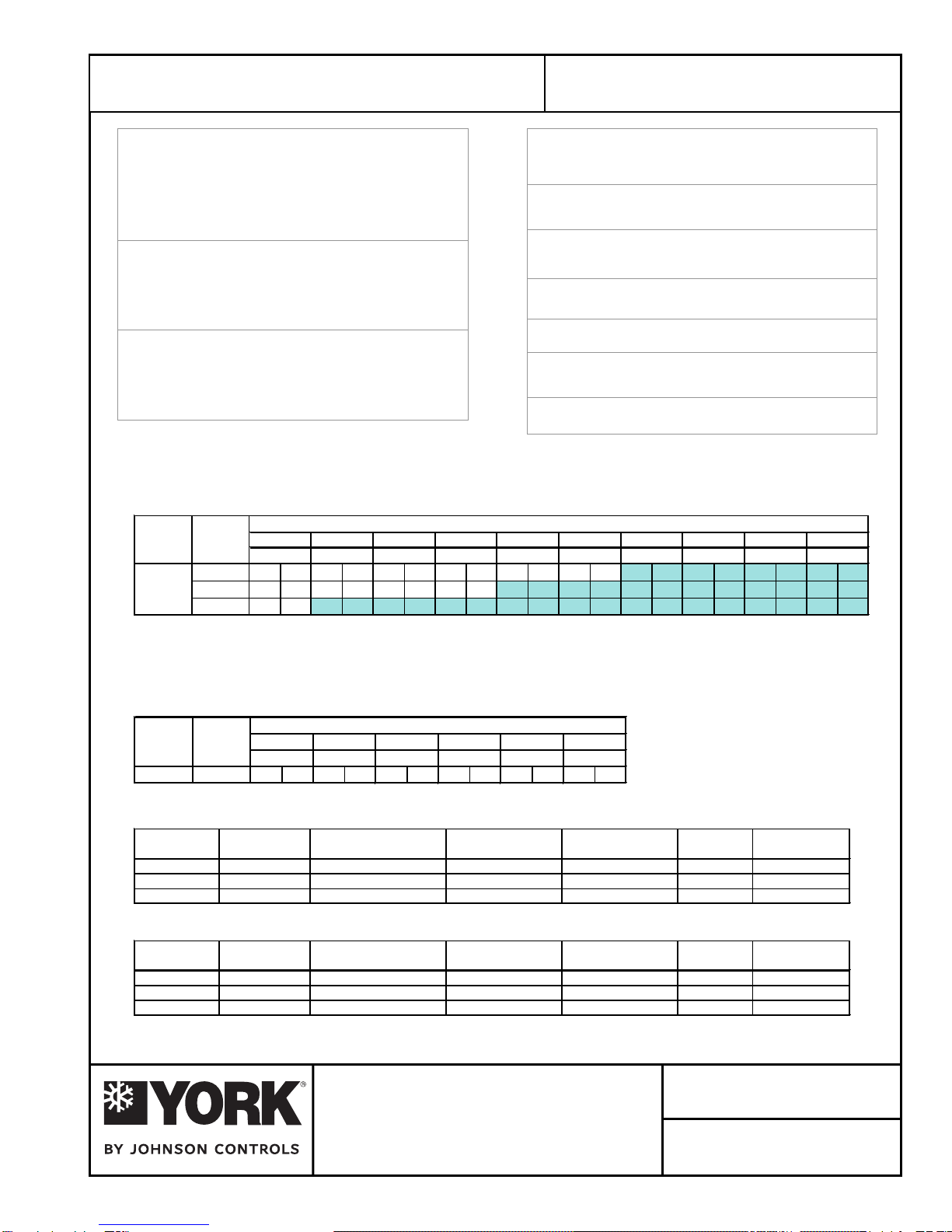
Gross Cooling Capacity [Btuh]:95,000*
Design CFM: 3,200
Energy Efficiency Ratio:11.55 EER**
Net Cooling Capacity [Btuh]: 92,000**
Net Cooling CFM: 3,200
Refrigerant: R22
Charge: 8.75 Lbs./ circuit
Compressor No./Type: 2/Scroll
Refrigerant Circuits: 2 / Independent
Evaporator Coil Face Area: 8.67 [sq ft]
Rows/FPI : 3/10
Refrigerant Control: TX Valve
Filters - Qty./Size: 4/14x25x2
Condenser Coil Face Area: 12.28 [sq ft]
Rows/FPI: 4/14
Evaporator Fan No./Type: 1/CENTRIFUGAL
Diameter x Width [in]:12x15
Drive: Adjustable Belt
Motor HP : 1.5 / 2.0
[Standard/Oversized]
Condenser Fan No./Type: 2/CENTRIFUGAL
Diameter x Width [in]:12x11
Drive: tleBelbatsujdA
Motor HP : 2.0
[Standard]
Operating Weight [lbs.]: 1005
Shipping Weight [lbs.]:1060
Condensate Connection: 3 / 4 NPT
*Cooling performance is rated at 95
°
F ambient, 80
°
F entering dry bulb, 67
°
F wet bulb
and CFM listed. Gross capacity does not include the effect of fan motor heat.
**Rated in accordance with ARI Standard 360-2000
NOTE:
1. At high evaporator air flows, and wet bulb conditions, condensate carry-over may occur. Adjust airflow downward as necessary.
2. Values include pressure drop from wet coil and clean filters.
3. Shaded areas indicate oversize motors.
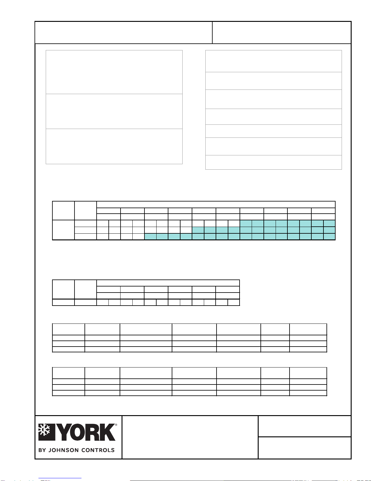
EVAPORATOR FAN PERFORMANCE
CONDENSER FAN PERFORMANCE
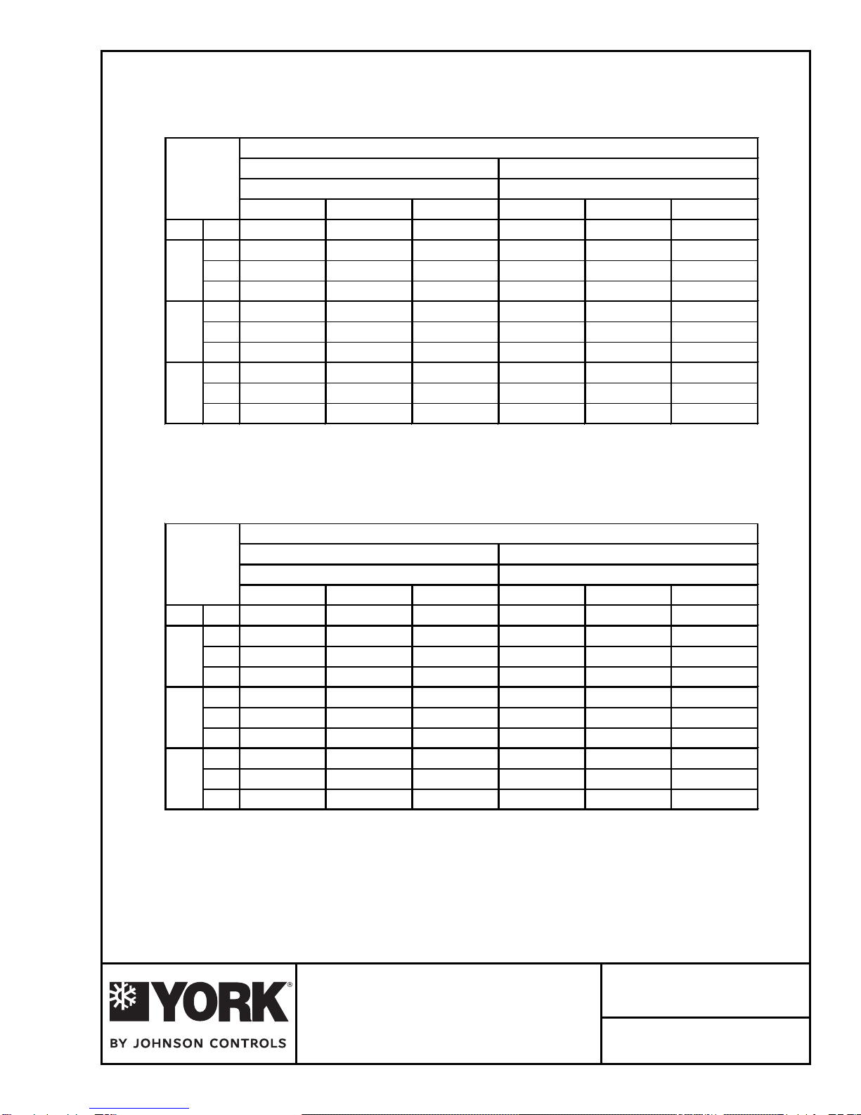
ELECTRICAL DATA – STANDARD MOTOR
ELECTRICAL DATA – OVERSIZED MOTOR
MODEL SUPPLY 0.2 0.4 0.6 0.8 1.0 1.2 1.4 1.6 1.8 2.0
# CFM RPM BHP RPM BHP RPM BHP RPM BHP RPM BHP RPM BHP RPM BHP RPM BHP RPM BHP RPM BHP
3000
3200DPV096
DPV096
DPV096
DPV096
DPV096
DPV096
DPV096
DPV096
734 0.76 809 0.89 881 1.02 950 1.17 1016 1.32 1079 1.47 1139 1.63 1196 1.79 1251 1.97 1303 2.17
771 0.90 843 1.03 911 1.17 977 1.32 1040 1.47 1101 1.63 1159 1.81 1214 2.01 ----
3400 811 1.06 879 1.20 944 1.35 1007 1.50 1068 1.66 1128 1.83 1187 2.01 - - ----
EXTERNAL STATIC PRESSURE - Inches W.C.
EXTERNAL STATIC PRESSURE - Inches W.C.
MODEL OUTDOOR 0.2 0.4 0.6 0.8 1.0 1.2
# CFM RPM BHP RPM BHP RPM BHP RPM BHP RPM BHP RPM BHP
737 1.19 811 1.38 882 1.59 951 1.82 1017 2.07 - -
MODEL VOLTAGE COMPRESSOR EVAPORATOR FAN CONDENSER FAN MIN. CCT. MAX FUSE /
#QTY RLA LRA HP FLA HP FLA AMPACITY CCT. BKR. AMP
208-230/3/60 2 @ 13.9 88.0 1.50 4.5 2.00 5.9 41.68 50
460/3/60 2 @ 7.1 44.0 1.50 2.1 2.00 2.8 20.97 25
575/3/60 2 @ 5.4 34.0 1.50 1.7 2.00 2.2 15.94 20
MODEL VOLTAGE COMPRESSOR EVAPORATOR FAN CONDENSER FAN MIN. CCT. MAX FUSE /
#QTY RLA LRA HP FLA HP FLA AMPACITY CCT. BKR. AMP
208-230/3/60 2 @ 13.9 88.0
2.00 5.9 2.00 5.9 43.08 50
460/3/60 2 @ 7.1 44.0
2.00 2.8 2.00 2.8 21.67 25
575/3/60 2 @ 5.4 34.0
2.00 2.2 2.00 2.2 16.44 20
4700
March 2008
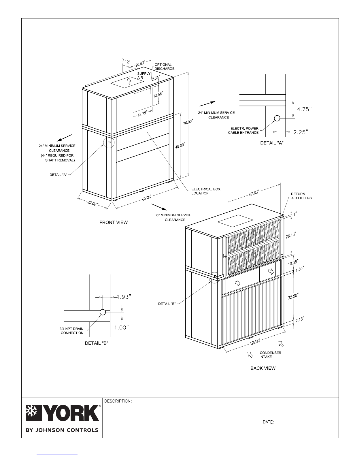
DPV096 VERTICAL UNIT
AIR-COOLED SELF-CONTAINED
Form YK145.12-PA4 (308)
1 of 4
Johnson Controls maintains a continuous product improvement policy, therefore specifications are subject to change without notice.