manuals.online logo
Brands
  1. Home
  2. •
  3. Brands
  4. •
  5. York
  6. •
  7. Chiller
  8. •
  9. York YCAZ33BA3 User manual

York YCAZ33BA3 User manual

This manual suits for next models

4

Other York Chiller manuals

York YK Series User manual

York

York YK Series User manual

York YB User manual

York

York YB User manual

York MaxE YK User manual

York

York MaxE YK User manual

York YLAA0285SE User manual

York

York YLAA0285SE User manual

York YCAS0250 Quick start guide

York

York YCAS0250 Quick start guide

York YZ MODEL A User manual

York

York YZ MODEL A User manual

York YCWS0313SC Installation and operating instructions

York

York YCWS0313SC Installation and operating instructions

York Millennium YDAS 410 Owner's manual

York

York Millennium YDAS 410 Owner's manual

York YPC User manual

York

York YPC User manual

York YMC2 User manual

York

York YMC2 User manual

York YD Quick start guide

York

York YD Quick start guide

York YCAV0267E Owner's manual

York

York YCAV0267E Owner's manual

York MaxE YK Series Manual

York

York MaxE YK Series Manual

York MAXE YST Quick start guide

York

York MAXE YST Quick start guide

York YLUA Series User manual

York

York YLUA Series User manual

York YCAV1039 Owner's manual

York

York YCAV1039 Owner's manual

York MILLENNIUM YG Series Manual

York

York MILLENNIUM YG Series Manual

York Millennium YK M3 M3 G4 THRU YK S6 S4 J2 Installation and operation manual

York

York Millennium YK M3 M3 G4 THRU YK S6 S4 J2 Installation and operation manual

York R-134a User manual

York

York R-134a User manual

York MILLENNIUM YK Manual

York

York MILLENNIUM YK Manual

York YCAS0693 Quick start guide

York

York YCAS0693 Quick start guide

York YHAU-CGN Owner's manual

York

York YHAU-CGN Owner's manual

York YCIV User manual

York

York YCIV User manual

York YCAL0019 Installation and operating instructions

York

York YCAL0019 Installation and operating instructions

Popular Chiller manuals by other brands

Trane RTAA-70 Installation & maintenance guide

Trane

Trane RTAA-70 Installation & maintenance guide

Carrier Omnizone 50BVC Installation, Start-Up, Service and Controls Operation and Troubleshooting

Carrier

Carrier Omnizone 50BVC Installation, Start-Up, Service and Controls Operation and Troubleshooting

Galletti PERFORMA MPE Series Technical manual

Galletti

Galletti PERFORMA MPE Series Technical manual

SMC Networks HRR Series manual

SMC Networks

SMC Networks HRR Series manual

Daikin EWAQ016CAW Installation and operation manual

Daikin

Daikin EWAQ016CAW Installation and operation manual

Trane CVHE Troubleshooting

Trane

Trane CVHE Troubleshooting

Moffat Friginox TSR-11SC Specification sheet

Moffat

Moffat Friginox TSR-11SC Specification sheet

Gree GWH07AGA-K6DNA1C Service manual

Gree

Gree GWH07AGA-K6DNA1C Service manual

MP Systems PURGE Series manual

MP Systems

MP Systems PURGE Series manual

Penguin COLD THERAPY CHILLER owner's manual

Penguin

Penguin COLD THERAPY CHILLER owner's manual

Telemark TVP-2000 Operation, installation and service manual

Telemark

Telemark TVP-2000 Operation, installation and service manual

TICA MINI VRF CHR Series Installation & operation manual

TICA

TICA MINI VRF CHR Series Installation & operation manual

MAXA A68 Installation and operation manual

MAXA

MAXA A68 Installation and operation manual

AERMEC NRL FC 2000 installation manual

AERMEC

AERMEC NRL FC 2000 installation manual

SABROE ChillPAC operating manual

SABROE

SABROE ChillPAC operating manual

Aqua Optima Corona Instructions for use

Aqua Optima

Aqua Optima Corona Instructions for use

Nordcap SKF 5 GN 1 manual

Nordcap

Nordcap SKF 5 GN 1 manual

lancer Siberian Elite Series Installation, operation & service manual

lancer

lancer Siberian Elite Series Installation, operation & service manual

manuals.online logo
manuals.online logoBrands
  • About & Mission
  • Contact us
  • Privacy Policy
  • Terms and Conditions

Copyright 2025 Manuals.Online. All Rights Reserved.

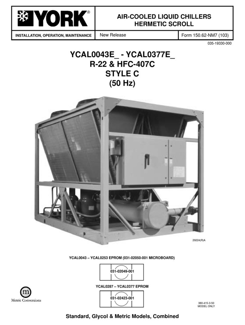
INSTALL., OPER., MAINTEN.
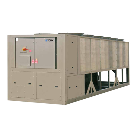
RecipPak LIQUID CHILLERS
AIR COOLED  RECIPROCATING HERMETIC
Supersedes: 150.44-NM3 in ERR only Form 150.44-NM4 (395)
60 HZ MODELS
YCAZ33BA3, YCAZ44BA3, YCAZ74BB3,
YCAZ77CB3, YCAZ88DB3
STYLE A*
*With EPROM 031-01096C001 (Standard, Brine & Metric Models, Combined)
26195A
200, 230, 460-3-60
YORK INTERNATIONAL
2
TABLE OF CONTENTS
GENERAL INFORMATION ............................................................................ 2
UNIT NOMENCLATURE ................................................................................ 3
OPERATIONAL LIMITATIONS ....................................................................... 7
PHYSICAL DATA ............................................................................................ 8
DIMENSIONS................................................................................................. 9
ELECTRICAL DATA ....................................................................................... 10
INSTALLATION .............................................................................................. 12
WIRING DIAGRAM ........................................................................................ 16
UNIT CONTROLS AND OPERATION ........................................................... 22
COMPRESSOR CAPACITY CONTROL ........................................................ 66
SYSTEM START-UP AND OPERATION ....................................................... 67
PREVENTATIVE MAINTENANCE ................................................................. 71
OPTIONS ....................................................................................................... 72
TROUBLESHOOTING CHART ...................................................................... 84
GENERAL DESCRIPTION
These packaged liquid chillers are completely self-con-
tained outdoor units shipped ready for final job installa-
tion requiring only liquid connections, power and con-
trol wiring. They are designed primarily for central sta-
tion air conditioning applications with normal installa-
tions being on roof-tops or on ground level beside the
building.
WARNING
HIGH VOLTAGE
is used in the operation of this equipment.
DEATH OR SERIOUS INJURY
may result if personal fail to observe safety precautions.
Work on electronic equipment should not be undertaken unless the individual(s) have been trained
in the proper maintenance of equipment and is (are) familiar with its potential hazards.
Shut off power supply to equipment before beginning work and follow lockout procedures. When
working inside equipment with power off, take special care to discharge every capacitor likely to
hold dangerous potential.
Be careful not to contact high voltage connections when installing or operating this equipment.
LOW VOLTAGE
DO NOT be misled by the term low voltage.
Voltages as low as 50 volts may cause death.
GENERAL INFORMATION
CODE STATUS
The units are designed in accordance with UL (200,
230, 460-3-60), N.E.C., ASHRAE/ANS STANDARD 15,
and ASME Codes.
FORM 150.44-NM4
3
YORK INTERNATIONAL
UNIT NOMENCLATURE
The model number denotes the following characteristics of the unit:
Y C A Z 7 4 B B 3 - 46 P A X
YORK
Chiller
Air Cooled
Compressor Type (J or Z)
System #1 Compressor Code:
3, 4, 7, 8 (See PHYSICAL DATA)
System #2 Compressor Code:
3, 4, 7, 8 (See PHYSICAL DATA)
Cooler Code:
B, C, D
Condenser Code:
A, B
S = Special
X = Blank if not used
Design Level
Type Start:
P = Part Wind
A = Across-The-Line
Voltage Code:
17 = 200-3-60
28 = 230-2-60
40 = 380-3-60
46 = 460-3-60
50 = 380/415-3-50
58 = 575-3-60
64 = 346-3-50
Fan Code:
2, 3
Compressor Series
No. of Cylinders (4, 6)
Displacement
No. of Steps of Unloading (0, 1, 2)
Style (B)
Motor Size Code
Voltage Code: 17 = 200-3-60
28 = 230-3-60
40 = 380-3-60
46 = 460-3-60
50 = 380/415-3-50
64 = 346 -3-50
Motor Manufacturer
(A = A.O. Smith, G = G.E.)
Z 6 W 2 B E -17 A
YORK INTERNATIONAL
4
CONDENSER FANS
CONTROL PANEL POWER PANEL
SYS 1
COMPRESSOR
COOLER
INLET
SHIPPING BRACKET
(Removed After Installation)
HEATER
COOLER
OUTLET
COOLER
SYS 2
COMPRESSOR
26195A(R)
FIG. 1  UNIT COMPONENTS
FORM 150.44-NM4
5
YORK INTERNATIONAL
FIG. 1  UNIT COMPONENTS (Contd)
LD01980
HOT GAS BY-PASS (OPTIONAL)
SYSTEM #1
25996A
YORK INTERNATIONAL
6
FIG. 1A  COMPRESOR COMPONENTS
27294A
6 CYLINDER
MODEL Z COMPRESSOR
OIL
PRESSURE
ACCESS CONN.
OIL LEVEL
SIGHT GLASS
OIL CHARGING
VALVE
TERMINAL
BOX
CAPACITY
CONTROL
SOLENOID
DISCHARGE
STOP VALVE
DATA
PLATE
OIL
PUMP
CRANKCASE
HEATER
27296A
SUPPRESSORS
MOTOR TERMINALS
MOTOR PROTECTOR (MP)
FORM 150.44-NM4
7
YORK INTERNATIONAL
OPERATIONAL LIMITATIONS
VOLTAGE LIMITATIONS
The following voltage limitations are absolute and op-
eration beyond these limits may cause serious dam-
age to the compressor.
VOLTAGES
TEMPERATURES AND FLOWS
MODEL LVG. WATER COOLER AIR ON
YCA TEMP. °F GPM COND. - °F
MIN.1MAX. MIN. MAX. MIN.2MAX.3
Z33BA3 40 50 75 250 0 130
Z44BA3 40 50 90 250 0 130
Z74BB3 40 50 90 250 0 130
Z77CB3 40 50 90 315 0 130
Z88DB3 40 50 130 390 0 130
NOTES:
1. Units can be used for brine temperatures between 15°F and 39°F
by resetting standard controls.
2. Operation below 25°F requires the Optional Low Ambient Kit
(Minimum recommended operating temperature is 0°F).
3. Operation above 115°F requires Optional High Ambient Kit (Maxi-
mum recommended operating temperature is 130°F).
4. The evaporator is protected against freeze-up to 20°F with an
electrical heater cable standard.
CAUTION: Excessive flow will cause damage to the
cooler. Do not exceed maximum Cooler
GPM. Special care should be taken when
multiple chillers are fed by a single
pump.
LD01981
CODE MODEL YCA
BZ33BA3
CZ44BA3, Z74BB3, Z77CB3
DZ88DB3
UNIT POWER MIN. MAX.
200-3-60 180 220
230-3-60 207 253
380-3-60 355 415
460-3-60 414 506
380/415-3-50 342 440
346-3-50 311 381
575-3-60 517 633
YORK INTERNATIONAL
8
PHYSICAL DATA
MODEL YCA 60 HZ Z33BA3 Z44BA3 Z74BB3 Z77CB3 Z88DB3
NOMINAL TONS 51.8 58.2 65.1 70.5 81.9
NO. OF REFRIG. CIRCUITS 22222
ACCESSIBLE (2)ZB4K1-B (2)ZB4M1-C (1)ZB6S1-D (2)ZB6S1-D (2)ZB6WZ-E
HERMETIC (35 HP) (45 HP) (55 HP) (55 HP) (65 HP)
COMPRESSOR MODEL (1)ZB4M1-C
(COMPRESSOR HP) (45 HP)
UNIT STANDARD 5 Steps 5 Steps 5 Steps 5 Steps 5 Steps
CAPACITY
CONTROL OPTIONAL N/A N/A 6 Steps 7 Steps 7 Steps
CONDENSER  DWP 450 PSIG 22222
NO. OF FANS (42" Dia Direct Drive)
HP/KW Each (850 RPM) 3/2.5 3/2.5 3/2.5 3/2.5 3/2.5
CFM TOTAL 30,300 30,300 34,400 34,400 34,400
COOLER  DUAL CIRCUITED
DWP  235 PSIG REF. SIDE,
150 PSIG WATER SIDE
DIA. x LENGTH 11" x 8" 11" x 8" 11" x 8" 12" x 8" 14" x 8"
WATER VOLUME (GALS.) 25 25 25 30 38
GPM MIN. 75 75 75 90 130
MAX. 250 250 250 315 390
SHIPPING AL Fins 4,800 5,150 5,550 5,675 5,850
WEIGHT CU Fins 5,350 5,700 6,375 6,500 6,675
LBS. OPERATING AL Fins 5,000 5,350 5,750 5,900 6,150
CU Fins 5,550 5,900 6,575 6,725 6,975
REFRIGERANT CHARGE Sys. 1 42 50 56 56 65
(LBS. R-22) Sys. 2 42 50 50 56 65
FORM 150.44-NM4
9
YORK INTERNATIONAL
WEIGHT DISTRIB. WATER CONN.
MODEL YCA (LBS.) INLET/OUTLET
A B C D DIA. (IN.)
Z33BA3 791 791 1707 1707 4
Z44BA3 858 858 1811 1811 4
Z74BB3 931 931 1948 1948 4
Z77CB3 935 935 2011 2011 6
Z88DB3 977 977 2079 2079 6
1. CLEARANCES  Recommended YORK required clearances to
prevent condenser air recirculation and faulty operation of units
are as follows:
Side to wall - 5'0" ** / Rear to wall - 8'0" ** / Front to wall -
8'0" ** / Top - 50'0" / Distance between adjacent units - 12'0"
* No more than one wall can be higher than the top of the unit.
Failure to heed recommended clearances may result in re-
duced system performance, nuisance shutdowns and ser-
vicing problems.
The area within the clearances shown above and area under the
unit must be kept clear of all obstructions that would impede free
air flow to the unit. In installations where winter operation is in-
tended and snow accumulations are expected, additional unit
height must be provided to insure full air flow.
2. Panel bottom to be punched in field to accommodate power wir-
ing conduit.
3. Use of isolators (optional) will increase height of unit approxi-
mately 6".
4. Drawings not to scale and are for planning purposes only. Refer
to QMS drawings for most up-to-date dimensions.
5. Be sure to review WARNINGS on page 2 prior to installation.
CAUTION
FAILURE TO HEED FOLLOWING MINIMUM RECOM-
MENDED CLEARANCES MAY RESULT IN REDUCED
SYSTEM PERFORMANCE, NUISANCE SHUT-
DOWNS, AND SERVICE PROBLEMS.
NOTES
CHILLER Y X
Z33BA3 7'2" 1'2-1/8"
Z44BA3 7'2" 1'2-1/8"
Z74BB3 7'2" 1'2-1/8"
Z77CB3 7'0" 1'3-1/8"
Z88DB3 7'1" 1'3-3/4"
DIMENSIONS
LD01982
LD01983
LD01984
YORK INTERNATIONAL
10
NOTES
1. Minimum Circuit Ampacity (MCA) is based on 125% of the rated load amps for the largest motor plus 100% of the loaded amps for all other
loads included in the circuit, per N.E.C. Article 430-24. If a Factory Mounted Control Transformer is provided, add the following to the
system #1 MCA values in the YCA Tables: -17, add 10 amps; -28, add 9 amps; -46, add 4 amps; -58, add 3 amps.
2. Minimum fuse size is based on 150% of the largest motor RLA plus 100% of the remaining RLAs. (U.L. Standard 1995, Section 36.1). It is
not recommended in applications where brown-outs, frequent starting and stopping of the unit, and/or operation at ambient temperatures
in excess of 95°F is anticipated.
3. Maximum dual element fuse size is based on 225% maximum plus 100% of the rated load amps for all other loads included in the circuit,
per N.E.C. 440-22.
4. The recommended disconnect switch is based on a minimum of 115% of the summation rated load amps of all the loads included in the
circuit, per N.E.C. 440-12A1.
5. Maximum HACR is based on 225% maximum plus 100% of the rated load amps for all loads included in the circuit, per circuit, per UL 1995
Fig 36.2.
6. The INCOMING WIRE RANGE is the minimum and maximum wire size that can be accommodated by the unit wiring lugs. The (1), (2),
(3), or (4) preceding the wire range indicates the number of termination points available per phase of the wire range specified. The (1 -2)
preceding the wire range indicates that a single double-barreled lug is available per phase that can accept up to two wires of the wire range
specified. (1) #1-600MCM OR (2) #1-250MCM indicates that a single lug is supplied and it will accept a single wire up to 600MCM or 2
wires up to 250MCM. Actual wire size and number of wires per phase must be determined based on ampacity and job requirements using
N.E.C. wire sizing information. The above recommendations are based on the National Electrical Code and using copper connectors only.
Field wiring must also comply with local codes.
7. A ground lug is provided for each compressor system to accommodate field grounding conductor per N.E.C. Article 250-54. A control circuit
grounding lug is also supplied. Incoming ground wire range is #6 - #2/0.
UNIT POWER SUPPLY INCOMING WIRE RANGE6SYS. 1 COMPR.
MODEL MAX SIZE
YCA MCA1DUAL ELEM DISC CKT BKR PW ACL YORK SUPPLIED NON-FUSED ACL/ PW/
FUSE SIZE MIN 4HACR START START DISCONNECT (OPTIONAL) RLA LRA LRA
MIN 2MAX 3TYPE 5
Z33BA3 -17 274 350 350 400 350 (2)#4-250MCM N/A (1) #1-600MCM OR (2) #1-250MCM 112 582 368
Z33BA3 -28 237 300 300 400 300 (2)#4-250MCM N/A (1) #1-600MCM OR (2) #1-250MCM 97 506 320
Z33BA3 -46 119 150 150 200 150 (2)#4-250MCM (2)#4-250MCM (1) #6-350MCM 48.5 253 160
Z33BA3 -58 95 125 125 200 125 (2)#4-250MCM (2)#4-250MCM (1) #6-350MCM 38.8 202 128
Z44BA3 -17 319 400 450 400 450 (2)#4-250MCM N/A (1) #1-600MCM OR (2) #1-250MCM 132 674 414
Z44BA3 -28 276 350 350 400 350 (2)#4-250MCM N/A (1) #1-600MCM OR (2) #1-250MCM 114 586 360
Z44BA3 -46 138 175 175 200 175 (2)#4-250MCM (2)#4-250MCM (1) #6-350MCM 57 293 180
Z44BA3 -58 110 150 150 200 150 (2)#4-250MCM (2)#4-250MCM (1) #6-350MCM 45.6 234 144
Z74BB3 -17 353 450 500 400 500 (2)#4-250MCM N/A (1) #1-600MCM OR (2) #1-250MCM 159 741 582
Z74BB3 -28 306 350 400 400 400 (2)#4-250MCM N/A (1) #1-600MCM OR (2) #1-250MCM 138 644 506
Z74BB3 -46 153 200 200 200 200 (2)#4-250MCM (2)#4-250MCM (1) #6-350MCM 69 322 253
Z74BB3 -58 122 150 175 200 175 (2)#4-250MCM (2)#4-250MCM (1) #6-350MCM 55 258 202
Z77CB3 -17 380 450 500 600 500 (2)#4-250MCM N/A (1-2) #2/0-500MCM 159 741 582
Z77CB3 -28 330 400 450 400 450 (2)#4-250MCM NM (1) #1-600MCM OR (2) #1-250MCM 138 644 506
Z77CB3 -46 165 200 225 200 225 (2)#4-250MCM (2)#4-250MCM (1) #6-350MCM 69 322 253
Z77CB3 -58 131 175 175 200 175 (2)#4-250MCM (2)#4-250MCM (1) #6-350MCM 55 258 202
Z88DB3 -17 468 6W 600 600 600 (2)#4-250MCM NM (1-2) #2/0-500MCM 198 880 675
Z88DB3 -28 406 500 500 600 500 (2)#4-250MCM NM (1-2) #2/0-500MCM 172 765 587
Z88DB3 -46 203 250 250 250 250 (2)#4-250MCM (2)*4-250MCM (1) #6-350MCM 86 383 294
Z88DB3 -58 162 200 225 200 225 (2)#4-250MCM (2)#4-250MCM (1) #6-350MCM 68.8 306 235
ELECTRICAL DATA