manuals.online logo
Brands
  1. Home
  2. •
  3. Brands
  4. •
  5. Zamel
  6. •
  7. Accessories
  8. •
  9. Zamel RCR-01 User manual

Zamel RCR-01 User manual

COOPERATION AND OPERATING RANGE
BATTERY CHANGE
* - 1-channel transmitters do not cooperate with roller blind controllers.
CAUTION: The given range concerns open area - an ideal condition without any
natural or articial obstacles. If there are some obstacles between a transmitter
and a receiver, it is advisable to decrease the range according to: wood and plas-
ter: from 5 to 20 %, bricks: from 10 to 40 %, reinforced concrete: from 40 to 80 %,
metal: from 90 to 100%, glass: from 10 to 20 %, Over- and underground medium
and high electrical power lines, radio and television transmitters, GSM transmit-
ters set close to a device system have also a negative inuence on the range.
Battery discharge status is signalled by several LED red diode ashes during
transmission time.
1. Remove the upper cover
of the transmitter.
2. Remove the upper print-
ed-circuit board.
3. Remove the batteries.
4. Mount new batteries.
Watch battery polarisa-
tion marked on the latch.
Wrong battery mounting
may cause device dam-
age.
5. Mount the upper printed-circuit board inserting the pins into the connectors.
6. Mount the upper cover’s latches into the latches of the base.
Symbol ROP-01 ROP-02 ROB-01 SRP-02 SRP-03 RWG-01 RWL-01 ROМ-01 ROМ-10 RDP-01 RTN-01
RNK-02 180 м 200 м 200 м 200 м 200 м 250 м 180 м 250 м 250 м 180 м 250 м
RNK-04 180 м 200 м 200 м 200 м 200 м 250 м 180 м 250 м 250 м 180 м 250 м
P-256/8 230 м 250 м 250 м 250 м 250 м 300 м 200 м 300 м 300 м 230 м 300 м
P-257/4 (2) 180 м 200 м 200 м 200 м 200 м 250 м 180 м 250 м 250 м 180 м 250 м
RNМ-10 230 м 250 м 250 м 250 м 250 м 300 м 200 м 300 м 300 м 230 м 300 м
RNP-01 160 м 180 м 180 м 180 м 180 м 200 м 160 м 200 м 200 м 160 м 200 м
RNP-02 160 м 180 м 180 м 180 м 180 м 200 м 160 м 200 м 200 м 160 м 200 м
RNL-01 160 м 180 м 180 м lack* lack* 200 м 160 м 200 м 200 м 160 м 200 м
RTN-01 200 м 200 м 200 м 200 м 200 м 250 м 200 м 250 м 250 м 200 м 250 м
RCR-01 160 м 180 м 180 м lack* lack* 200 м 160 м 200 м 200 м 160 м 200 м
RTI-01 160 м 180 м 180 м 180 м 180 м 200 м 160 м 200 м 200 м 160 м 200 м
RXМ-01 230 м 250 м 250 м 250 м 250 м 300 м 200 м 300 м 300 м 230 м 300 м
Sensitivity potentiometer
PROG push-button
Optic signalling range of operation
Motion sensor lens
Battery bases
Switches of operation modes
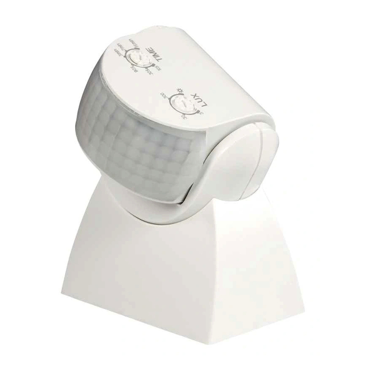
RADIO MOTION SENSOR
RCR-01
TECHNICAL DATA
Input rated voltage: 3 V DC
Battery type: 2 x AAA / R03
Battery life: 1 year (depending on use)
Liczba kanałów: 1
Twilight sensor adjustment range: 2 ÷ 20 lx
Transmission: radio 868,32 MHz
Coding way: unidirectional
Coding: addressing transmission
Range: up to 200 m in the open area
Optic signalling of transmitter’s operation: LED red diode
Ambient temperature range: -10 ÷ +55 °C
Operating position: free
Casing mounting: wall plugs, double-sided adhesive tape
Casing protection degree: IP20 (EN 60529)
Protection level: III
Pollution degree: 2
Dimensions: Ø70 x 40 mm
Weight: 0,070 kg
Reference standard: ETSI EN 300 220-1,
ETSI EN 300 220-2
OPERATION
The device can operate in two modes: 1. Motion sensor, 2. Motion sensor with twilight
switch. Operation modes are adjusted by means of two switches which are under the
top cover of the sensor. Mode 1 - adjust the switch to „C” position, Mode 2 - adjust the
switch to „F” position. It is important to adjust the switches in the same position,
otherwise they operate incorrectly. In the operation mode with a twilight sensor
adjust luminous density by means of a potentiometer. Potentiometer adjustment to
„” sign means operation adjustment during daylight - about 20 lx, and potentiometer
adjustment to „ ” sign means operation adjustment during night - about 2 lx. Radio
transmission range (up to 200 m - depending on a receiver) can be increased by
means of a retransmitter or few RTN-01 retransmitters.

MOUNTING
The sensor can be mounted in any place by means of double-sided adhesive tape or
wall plugs 5x(3x30) mm.
Mounting by means of wall plugs:
Remove the upper cover - to do it put a screwdriver into a slot between the cover
and the base and switch it lifting up the cover at the same time.
Choose a place on the wall to mount the RCR-01 device, make two holes corre-
sponding mounting holes from the transmitter’s base.
Set wall plugs in the holes.
Fix the base by means of tightening screws into wall plugs.
Place the upper cover’s latches into the latches of the base.
CAUTION: The device has factory mounted batteries secured with special sep-
arator. Before the rst device use remove the separator.
Sensitivity potentiometer
PROG push-button
Optic signalling range of operation
Motion sensor lens
Battery bases
Switches of operation modes
Sensitivity potentiometer
PROG push-button
Optic signalling range of operation
Motion sensor lens
Battery bases
Switches of operation modes
PROGRAMMING OF RECEIVERS
Mode 1. Motion sensor (operation modes’ switches in C-C position)
In this mode the receiver should be programmed to operate in time mode; time should be
adjusted to 15 seconds. When there is a movement within detection area the device sends
a signal to the receiver every 10 seconds. After a signal has been sent, adjusted time t is
counted again.
CAUTION: After each pressing of a push-button in a sensor, there are 10 seconds to
start the next programming step. After 10 seconds LED diode switches off in the sen-
sor and RCR-01 device starts usual operation (programming procedure must be started
again.
Press PROG push-button of RCR-01, next release the push-button. LED red diode
switches on under the lens (constant signal).
Press PROG push-button to adjust the receiver to programming mode. LED red diode
in the receiver switches on (constant signal).
Press PROG push-button of RCR-01 device and then release it. LED red diode in the
receiver switches on (rst signal pulsates, next the signal is constant).
Press PROG push-button of RCR-01 device and then release it. LED red diode in the re-
ceiver switches on (signal pulsates), and then switches off - THE SENSOR IS ADDED.
Wait until LED diode in RCR-01 device switches off.
Mode 2. Motion sensor with twilight switch (operation modes’ switches in F-F posi-
tion).
In this mode the receiver should be programmed to operate in monostable mode.
When there is a movement within detection area the sensor sends a switch on signal
to the receiver.
The sensor sends a switch off signal after 20 seconds from the moment of no move-
ment in the detection area.
Press PROG push-button of RCR-01device, next release the push-button. LED red di-
ode switches on under the lens (constant signal).
Press PROG push-button of RCR-01 device again for a longer time.
Press PROG pushbutton to adjust the receiver to the programming mode. LED red
diode in the receiver switches on (constant signal).
Release PROG pushbutton of RCR-01 device. LED red diode in the receiver switches
on (rst signal pulsates, next the signal is constant).
Press PROG push-button of RCR-01 device and then release it. LED red diode in the re-
ceiver switches on (signal pulsates), and then switches off - THE SENSOR IS ADDED.
Wait until LED diode in RCR-01 device switches off.
An exemplary programming procedure with the use of RWL-01 receiver.
The procedure for the rest of radio EXTA FREE transmitters is analogous.

Other manuals for RCR-01

2

Other Zamel Accessories manuals

Zamel Exta CAH-01 User manual

Zamel

Zamel Exta CAH-01 User manual

Zamel sundi SONATA ST-916 User manual

Zamel

Zamel sundi SONATA ST-916 User manual

Zamel Sundi BOWL BELL User manual

Zamel

Zamel Sundi BOWL BELL User manual

Zamel SUNDI VIVO GNS-224 User manual

Zamel

Zamel SUNDI VIVO GNS-224 User manual

Zamel exta MCR-01 User manual

Zamel

Zamel exta MCR-01 User manual

Zamel SUNDI VETRO GNS-247 User manual

Zamel

Zamel SUNDI VETRO GNS-247 User manual

Zamel sundi SUITA User manual

Zamel

Zamel sundi SUITA User manual

Zamel sundi ST-330 User manual

Zamel

Zamel sundi ST-330 User manual

Zamel sundi ST-905 User manual

Zamel

Zamel sundi ST-905 User manual

Zamel Sundi GLASSO User manual

Zamel

Zamel Sundi GLASSO User manual

Zamel Sundi OVAL ST-990 User manual

Zamel

Zamel Sundi OVAL ST-990 User manual

Zamel SUNDI VIVO GNT-224 User manual

Zamel

Zamel SUNDI VIVO GNT-224 User manual

Zamel sundi TANGO ST-910 User manual

Zamel

Zamel sundi TANGO ST-910 User manual

Zamel DISCO User manual

Zamel

Zamel DISCO User manual

Zamel exta CKH-01 User manual

Zamel

Zamel exta CKH-01 User manual

Zamel SUNDI FORTE GNT-223-BIA User manual

Zamel

Zamel SUNDI FORTE GNT-223-BIA User manual

Zamel POP ST-940 User manual

Zamel

Zamel POP ST-940 User manual

Zamel sundi LOOPO ST-366 User manual

Zamel

Zamel sundi LOOPO ST-366 User manual

Zamel Sundi Twist User manual

Zamel

Zamel Sundi Twist User manual

Zamel ST-940 User manual

Zamel

Zamel ST-940 User manual

Zamel Sundi Two-Tone User manual

Zamel

Zamel Sundi Two-Tone User manual

Zamel BIM-BAM GNS-921 User manual

Zamel

Zamel BIM-BAM GNS-921 User manual

Zamel TURBO GNS-931 User manual

Zamel

Zamel TURBO GNS-931 User manual

Zamel Sundi BLUES ST-960 User manual

Zamel

Zamel Sundi BLUES ST-960 User manual

Popular Accessories manuals by other brands

Eaton CurrentWatch EPRM Series installation instructions

Eaton

Eaton CurrentWatch EPRM Series installation instructions

Carefree MARQUEE installation manual

Carefree

Carefree MARQUEE installation manual

La Crosse Technology TX141-Bv2 quick start guide

La Crosse Technology

La Crosse Technology TX141-Bv2 quick start guide

Coiltek CS-5100 Series operating manual

Coiltek

Coiltek CS-5100 Series operating manual

Emos G1180 manual

Emos

Emos G1180 manual

Saje WELLNESS 101 instruction manual

Saje

Saje WELLNESS 101 instruction manual

Philips HF3651/01 Troubleshooting

Philips

Philips HF3651/01 Troubleshooting

Baumer 10161026 manual

Baumer

Baumer 10161026 manual

FEBREZE ambi Pur3263 Usage instructions

FEBREZE

FEBREZE ambi Pur3263 Usage instructions

TP-Link Kasa Smart KP400 user guide

TP-Link

TP-Link Kasa Smart KP400 user guide

Baltimore Aircoil Company VT1 Series Operating and maintenance instructions

Baltimore Aircoil Company

Baltimore Aircoil Company VT1 Series Operating and maintenance instructions

Balluff BAE SA-OH-064-NP-DP02 user guide

Balluff

Balluff BAE SA-OH-064-NP-DP02 user guide

Koolatron Fun Kool P25 user manual

Koolatron

Koolatron Fun Kool P25 user manual

Neurio W1-S user guide

Neurio

Neurio W1-S user guide

MS Electronics WMPD3 Product guide

MS Electronics

MS Electronics WMPD3 Product guide

ADC FlexWave nano Hardware installation

ADC

ADC FlexWave nano Hardware installation

Dorner 3200 Series Installation, maintenance & parts manual

Dorner

Dorner 3200 Series Installation, maintenance & parts manual

XD COLLECTION P322.14 Series manual

XD COLLECTION

XD COLLECTION P322.14 Series manual

manuals.online logo
manuals.online logoBrands
  • About & Mission
  • Contact us
  • Privacy Policy
  • Terms and Conditions

Copyright 2025 Manuals.Online. All Rights Reserved.