manuals.online logo
Brands
  1. Home
  2. •
  3. Brands
  4. •
  5. Zamel
  6. •
  7. Accessories
  8. •
  9. Zamel SRP-02 User manual

Zamel SRP-02 User manual

REMOTE CONTROL SOCKET RWG-01 MANUAL INSTRUCTION
ZAMEL Sp. z o.o.
ul. Zielona 27, 43-200 Pszczyna, Poland
tel. +48 (32) 210 46 65, fax +48 (32) 210 80 04
www.zamelcet.com, e-mail: [email protected]
VER. 004_11.07.2011
The device is designed
for single-phase instal-
lation and must be in-
stalled in accordance
with standards valid in a
particular country. The de-
vice should be connected
according to the details in-
cluded in this operating manual. Installation,
connection and control should be carried out
by a qualied electrician staff, who act in ac-
cordance with the service manual and the
device functions.
In case of casing dismantling an electric
shock may occur, and the guarantee is lost
then. Before installation make sure the con-
nection cables are not under voltage. The
cruciform head screwdriver 3,5 mm should
be used to instal the device. Improper trans-
port, storage, and use of the device inuence
its wrong functioning. It is not advisable to in-
stal the device in the following cases: if any
device part is missing or the device is dam-
aged or deformed. In case of improper func-
tioning of the device contact the producer.
CAUTION!
APPEARANCE
FEATURES
TECHNICAL DATA
DESCRIPTION
● cooperation with wireless EXTA
FREE system transmitters (it is ob-
ligatory to purchase it separately),
● lighting, heating control and other
receivers control,
● easy mounting in 230V AC socket,
● five operation modes: switching on
mode, switching off, monostable,
bistable, time (switch off delay),
● wide range of operation (up to 300 m),
● radio transmission and relay status
are optically signalled,
● low current consumption, possibil-
ity of constant work
● possibility of widening operation
range by means of RTN-01 re-
transmitter.
Remote control socket RWG-01 is
used to connect any 230 V AC rece-
iver of 4000 VA and to wireless control
by means of different EXTA FREE sys-
tem transmitters. The device can be
mounted without any additional tools
or interference in existing wiring - it is
directly mounted to 230 V AC socket.
RWG-01
Input rated voltage: 230 V AC
Input voltage tolerance: -15 ÷ +10 %
Nominal frequency: 50 / 60 Hz
Nominal power consumption: 0,29 W
Optic signalling of power supply: LED green diode
Number of operation modes: 5
Number of channels: 1
Transmission: radio 868,32 MHz
Coding way: unidirectional
Coding: addressing transmission
Maximum number of transmitters: 32
Range: up to 300 m in the open area
Time adjustment: 1 sec. ÷ 18 hours (every second)
Optic signalling of device operation: LED red diode
Relay contact parameters: 1NO 16A / 250V~ AC1 4000 VA
Ambient temperature range: -10 ÷ +55 oC
Operating position: free
Casing mounting: 230 V~ socket
Casing protection degree: IP20 (EN 60529)
Protection level: II
Overvoltage category: II
Pollution degree: 2
Surge voltage: 1 kV (EN 61000-4-5)
Dimensions: 160 x 66 x 90 mm
Weight: 0,160 kg
Reference standard:
EN 60669, EN 60950, EN 61000
The symbol means selective
collecting of electrical and electronic
equipment.
It is forbidden to put the used
equipment together with other waste.
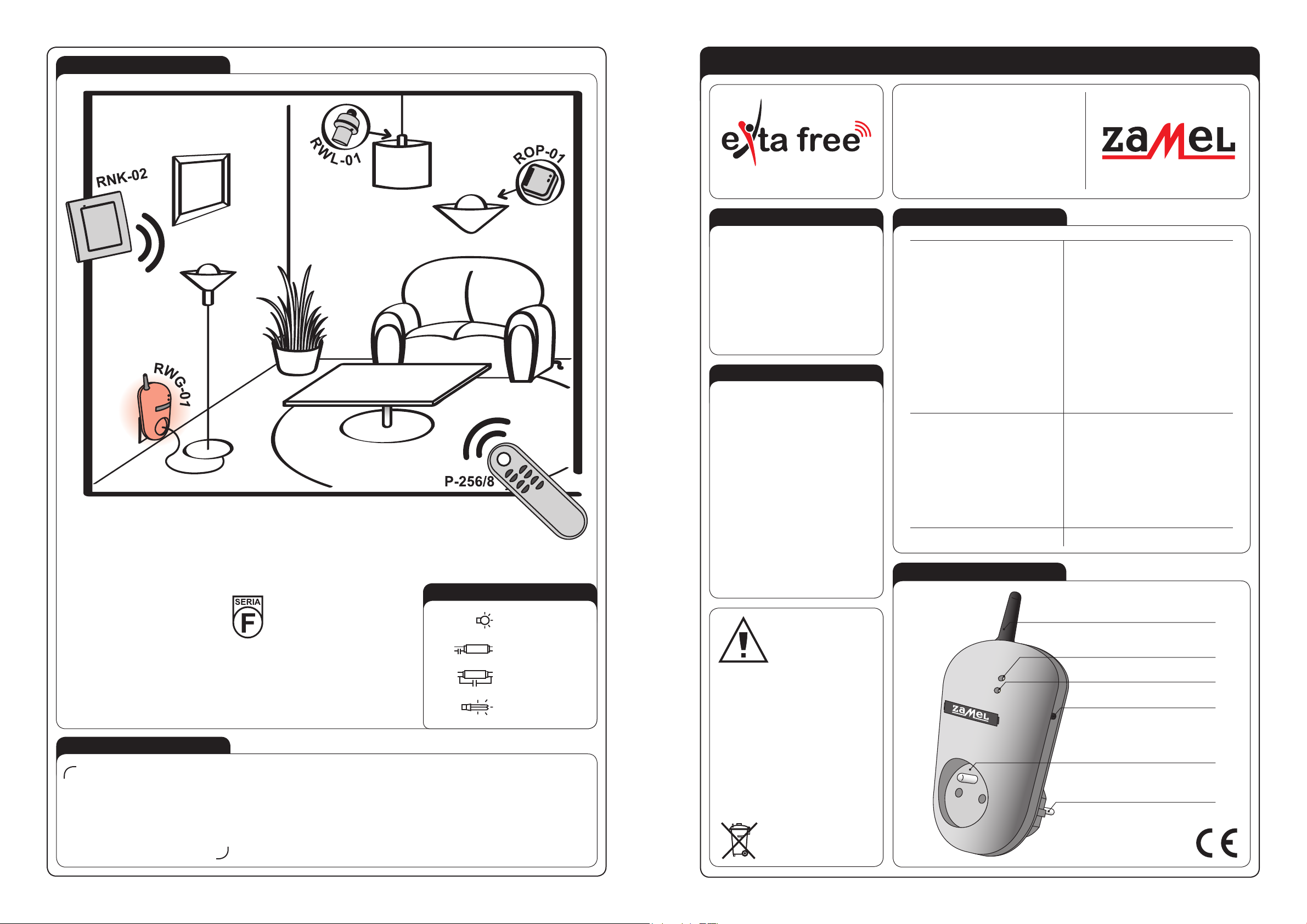
Antenna
Optic signalling of transmitters’
switching on
Programming push-button
Receiver’s socket
Power supply plug
Optic signalling of input voltage
APPLICATION
Remote control socket RWG-01 operates as a receiver of 8-channel remote control P-256/8 and of
2–channel button radio transmitter RNK-02 (light sources control - switch on / switch off). Presented
transmitters can also control operation of 1-channel radio receiver ROP-01 or radio lighting switch
RWL-01 (lighting operation).
CAPACITY
2000 W AC5b
1000 W AC5a
750 W AC5a
500 W AC5a
WARRANTY CARD
There is 24 months guarantee on the product
1. ZAMEL provides a two-year warranty for its products.
2. The ZAMEL warranty does not cover: a) mechanical defects resulting from transport, loading / unloading or other circumstances
b) defects resulting from incorrect installation or operation of ZAMEL products; c) defects resulting from any changes made by CUS-
TOMERS or third parties, to products sold or equipment necessary for the correct operation of products sold; d) defects resulting
from force majeure or other aleatory events for which ZAMEL is not liable; e) power supply (batteries) to be equipped with a device
in the moment of sale (if they appear);
3. All complaints in relation to the warranty must be provided by the CUSTOMER in writing to the retailer after discovering a defect.;
4. ZAMEL will review complaints in accordance with existing regulations.;
5. The way a complaint is settled, e.g. replacement of the product, repair or refund, is left to the discretion of ZAMEL.
6. Guarantee does not exclude, does not limit, nor does it suspend the rights of the PURCHASER resulting from the discrepancy
between the goods and the contract.
Salesman stamp and signature, date of sale
The ZAMEL company devices
which are characterised
with this sign can cooperate
with each other.
VER. 004_11.07.2011
TIME PROGRAMMING
RADIO TRANSMITTERS DELETION
COOPERATION AND OPERATING RANGE
Symbol ROP-01 ROP-02 ROB-01 SRP-02 SRP-03 RWG-01 RWL-01 ROM-01 ROM-10 RDP-01 RTN-01
RNK-02 180 m 200 m 200 m 200 m 200 m 250 m 180 m 250 m 250 m 180 m 250 m
RNK-04 180 m 200 m 200 m 200 m 200 m 250 m 180 m 250 m 250 m 180 m 250 m
P-256/8 230 m 250 m 250 m 250 m 250 m 300 m 200 m 300 m 300 m 230 m 300 m
P-257/4 (2) 180 m 200 m 200 m 200 m 200 m 250 m 180 m 250 m 250 m 180 m 250 m
RNM-10 230 m 250 m 250 m 250 m 250 m 300 m 200 m 300 m 300 m 230 m 300 m
RNP-01 160 m 180 m 180 m 180 m 180 m 200 m 160 m 200 m 200 m 160 m 200 m
RNP-02 160 m 180 m 180 m 180 m 180 m 200 m 160 m 200 m 200 m 160 m 200 m
RNL-01 160 m 180 m 180 m lack* lack* 200 m 160 m 200 m 200 m 160 m 200 m
RTN-01 200 m 200 m 200 m 200 m 200 m 250 m 200 m 250 m 250 m 200 m 250 m
RCR-01 160 m 180 m 180 m lack* lack* 200 m 160 m 200 m 200 m 160 m 200 m
RTI-01 160 m 180 m 180 m 180 m 180 m 200 m 160 m 200 m 200 m 160 m 200 m
RXM-01 230 m 250 m 250 m 250 m 250 m 300 m 200 m 300 m 300 m 230 m 300 m
* - 1-channel transmitters do not cooperate with roller blind controllers.
CAUTION: The given range concerns open area - an ideal condition without any natural or articial obstacles. If there are some obstacles between a transmitter and a receiver,
it is advisable to decrease the range according to: wood and plaster: from 5 to 20 %, bricks: from 10 to 40 %, reinforced concrete: from 40 to 80 %,
metal: from 90 to 100% , glass: from 10 to 20 %.
Over- and underground medium and high electrical power lines, radio and television transmitters, GSM transmitters set close to a device system have also a negative
inuence on the range.
RADIO TRANSMITTERS’ PROGRAMMING
OPERATION
The device can operate in ve modes:
MONOSTABLE
the relay operates only
while pressing transmit-
ter’s push-button.
BISTABLE
(one push-button) the
device changes relay
status cyclically always
after pressing the same push-
button.
SWITCH ON
the device switches on
after pressing the push-
button.
SWITCH OFF
the device switches off
after pressing the push-
button.
TIME
the device switches
off according to the
adjusted time (tp),
but it may be switched off before
adjusted time nishes. Default
settings - 15 seconds.
CAUTION! Adjusted time can-
not be deleted.
TRANSMITTERS RECEIVERS
RNK-02
2–channel button
radio transmitter
RNL-01
Radio
foot transmitter
ROP-01
1-channel
radio receiver
RWL-01
Radio lighting
switch
RNK-04
4-channel button
radio transmitter
RTI-01
IR/EXTA FREE
transceiver
ROP-02
2-channel
radio receiver
RWG-01
Remote control
socket
P-256/8
8-channel
remote control
RNM-10
4-channel radio
modular transmitter
RDP-01
1-channel
radio dimmer
SRP-02
Radio roller blinds
controller
P-257/4
4-channel
remote control
RNP-01
4-channel
radio transmitter
ROB-01/12-24V
Radio
gate controller
SRP-03
Central radio roller
blinds controller
P-257/2
2-channel
remote control
RNP-02
4-channel
radio transmitter
ROM-01
1-channel radio
modular receiver
ROM-10
2-channel
radio modular receiver
RCR-01
Radio
motion sensor
RXM-01
RS-485/EXTA FREE
Transceiver
ACCESSORIES
ANT-01
External antenna
RTN-01
Retransmitter
Press transmitter’s
push-button for
a longer time.
Press the transmitter’s push-button
for a longer time. LED red diode switches on
(rst signal pulsates, next the signal is constant).
Press the transmitter’s push-button and then
release it. LED red diode switches on
(rst signal pulsates, next the signal is constant).
Press and release transmitter’s rst push-
button. LED red diode switches on (rst
signal pulsates, next the signal is constant).
Release transmitter’s push-
button. LED red diode switches
on (rst signal pulsates, next
the signal is constant).
Release transmitter’s push-button. LED
red diode switches on (the signal pulsates),
next the LED red diode switches off - it
means the TRANSMITTER IS ADDED.
Press and release the same transmitter’s
push-button. LED red diode switches on
(signal pulsates) and then switches off -
THE TRANSMITTER IS ADDED.
Press and release the second transmitter’s
push-button. LED red diode switches on
(the signal pulsates) and next it switches
off - THE TRANSMITTER IS ADDED.
Press the same transmitter’s push-
-button and release it. LED red diode
switches on (the signal pulsates) and
next it switches off - THE TRANS-
MITTER IS ADDED.
MONOSTABLE mode:
BISTABLE mode:
SWITCH ON/SWITCH OFF mode (two push-buttons):
TIME mode (one push-button):
An exemplary programming procedure with the use of P-257/2 remote controller. The procedure for the rest of radio EXTA FREE transmitters
is analogous. CAUTION: Every transmitter can cooperate with RWG-01 in a different mode, depending on how they were added to
the device. One transmitter can be added during one programming cycle. Full memory is signalled with pulsating LED red diode.
Press PROG push-button of RWG-01 device
for a longer time until LED red diode switches on
(constant signal). Next release PROG push-button.
Press PROG push-button of RWG-01 device
for a longer time until LED red diode switches on
(constant signal). Next release PROG push-button.
Press PROG push-button of RWG-01 device
for a longer time until LED red diode switches on
(constant signal). Next release PROG push-button.
Press PROG push-button of RWG-01 device
for a longer time till LED red diode switches on
(constant signal). Next release PROG push-button.
Press PROG push-button of RWG-01
device for a longer time.
After 5 seconds LED red diode switches on
(signal pulsates) and then it switches off.
Release the push-button in RWG-01
- MEMORY IS DELETED.
Press PROG push-button of RWG-01 device for a longer time till
LED red diode switches on (constant signal). Next release PROG
push-button. Wait (for about 5 seconds) till LED red diode switches
on (rst signal pulsates, next the signal is constant).
After the adjusted time is
nished (the number of LED
red diode ashes) press
PROG push-button and then
release it - TIME IS ADDED.
Press PROG push-button of RWG-01 device
and then release it. LED red diode switches
off and then switches on (signal pulsates).
Every LED diode pulse equals 1 second.
Maximum time is 18 hours.
1s 2s ns

Other manuals for SRP-02

1

This manual suits for next models

10

Other Zamel Accessories manuals

Zamel sundi VIBRO User manual

Zamel

Zamel sundi VIBRO User manual

Zamel SUNDI TURBO GNT-931-BEZ User manual

Zamel

Zamel SUNDI TURBO GNT-931-BEZ User manual

Zamel SUNDI VIVO GNS-224 User manual

Zamel

Zamel SUNDI VIVO GNS-224 User manual

Zamel ST-930 User manual

Zamel

Zamel ST-930 User manual

Zamel SUNDI FORTE GNT-223-BIA User manual

Zamel

Zamel SUNDI FORTE GNT-223-BIA User manual

Zamel Sundi BOWL BELL User manual

Zamel

Zamel Sundi BOWL BELL User manual

Zamel sundi TANGO ST-910 User manual

Zamel

Zamel sundi TANGO ST-910 User manual

Zamel Sundi GLASSO User manual

Zamel

Zamel Sundi GLASSO User manual

Zamel BULIK DRS-982H User manual

Zamel

Zamel BULIK DRS-982H User manual

Zamel Exta SOS-01 User manual

Zamel

Zamel Exta SOS-01 User manual

Zamel Exta CAH-01 User manual

Zamel

Zamel Exta CAH-01 User manual

Zamel sundi ST-330 User manual

Zamel

Zamel sundi ST-330 User manual

Zamel LARGO GNS-208 User manual

Zamel

Zamel LARGO GNS-208 User manual

Zamel sundi BULIK User manual

Zamel

Zamel sundi BULIK User manual

Zamel Sundi OVAL ST-990 User manual

Zamel

Zamel Sundi OVAL ST-990 User manual

Zamel Sundi One-Tone User manual

Zamel

Zamel Sundi One-Tone User manual

Zamel ST-940 User manual

Zamel

Zamel ST-940 User manual

Zamel sundi BUZZER DNT-255 User manual

Zamel

Zamel sundi BUZZER DNT-255 User manual

Zamel RCR-01 User manual

Zamel

Zamel RCR-01 User manual

Zamel BIM-BAM GNS-921 User manual

Zamel

Zamel BIM-BAM GNS-921 User manual

Zamel sundi LOOPO ST-366 User manual

Zamel

Zamel sundi LOOPO ST-366 User manual

Zamel SUNDI VETRO GNS-247 User manual

Zamel

Zamel SUNDI VETRO GNS-247 User manual

Zamel BIM-BAM GNT-921 User manual

Zamel

Zamel BIM-BAM GNT-921 User manual

Zamel sundi SONATA ST-916 User manual

Zamel

Zamel sundi SONATA ST-916 User manual

Popular Accessories manuals by other brands

Bison BA735QC instruction manual

Bison

Bison BA735QC instruction manual

CALECTRO CPS-D-SW Installation instruction

CALECTRO

CALECTRO CPS-D-SW Installation instruction

Royal Catering RCWI-428L user manual

Royal Catering

Royal Catering RCWI-428L user manual

DPM WH518DW manual

DPM

DPM WH518DW manual

Anker PowerCore+ 26800 Welcome guide

Anker

Anker PowerCore+ 26800 Welcome guide

Bisque TheSky Fusion quick start guide

Bisque

Bisque TheSky Fusion quick start guide

Tecsis P3297 operating instructions

Tecsis

Tecsis P3297 operating instructions

Manitowoc K00343 installation instructions

Manitowoc

Manitowoc K00343 installation instructions

Doro MemoryPlus 335 owner's guide

Doro

Doro MemoryPlus 335 owner's guide

PCB Piezotronics 103B01 Installation and operating manual

PCB Piezotronics

PCB Piezotronics 103B01 Installation and operating manual

Sygonix XJY-USB-EU-01D-QC3.0 operating instructions

Sygonix

Sygonix XJY-USB-EU-01D-QC3.0 operating instructions

CEEZAM CZ00.275 manual

CEEZAM

CEEZAM CZ00.275 manual

Sygonix 1882365 operating instructions

Sygonix

Sygonix 1882365 operating instructions

Fisher Scientific Isotemp Series user manual

Fisher Scientific

Fisher Scientific Isotemp Series user manual

SME V-12 Series Information sheet

SME

SME V-12 Series Information sheet

Honeywell Q348A manual

Honeywell

Honeywell Q348A manual

SCHUNK FT Assembly and operating manual

SCHUNK

SCHUNK FT Assembly and operating manual

Beurer LA 20 Instructions for use

Beurer

Beurer LA 20 Instructions for use

manuals.online logo
manuals.online logoBrands
  • About & Mission
  • Contact us
  • Privacy Policy
  • Terms and Conditions

Copyright 2025 Manuals.Online. All Rights Reserved.