manuals.online logo
Brands
  1. Home
  2. •
  3. Brands
  4. •
  5. Zamel
  6. •
  7. Measuring Instrument
  8. •
  9. Zamel EXTA LDM-10 User manual

Zamel EXTA LDM-10 User manual

VOLTAGE INDICATOR LDM - 10 INSTRUCTION MANUAL
FEATURES
TECHNICAL PARAMETERS
DESCRIPTION
APPEARANCE
ver. 0.4.2 _ 2006.06.20_11:00
ی Graphic presentation of the one-
phase voltage supply system le-
vel,
ی voltageindicationwiderangefrom
195to245V~,
ی voltagevalueproportionaltograph
heightscalerange5V,
ی indicationstability,
ی indicated voltage value accuracy
±2,5V,
ی voltage critical values are signal-
led by diodes marked „≤195 V”,
„≥245V”,
ی TH-35DINrailinstallation.
LDM - 10
Input(supply)terminals: L,N
Inputratedvoltage: 230V~
Inputvoltagetolerance: from-15to+10%
Ratedfrequency: 50/60Hz
Ratedpowerconsumption: 24mA
Voltageindicator: 11LEDdiodes
Voltageindicatoraccuracy: ±2,5V
Numberofterminalclamps: 2
Sectionofconnectingcables: from0,2to2,5mm2
Ambienttemperaturerange: from-20to+45oC
Operatingposition: free
Mounting: TH35rail(PN-EN60715)
Protectiondegree: IP20(PN-EN60529)
Protectionclass: II
Overvoltagecategory: II
Pollutiondegree: 2
Impulsevoltage: 1kV(PN-EN61000-4-5)
Dimensions(height/width/depth): monomodular(17,5mm)90x17,5x66mm
Weight: 56g
Referencestandards: PN-EN60947-5-1,PN-EN60947-1
PN-EN61000-4-2,3,4,5,6,11
The LDM-10 device is used for
graphicpresentationoftheone-phase
voltage supply system level. Voltage
value is shown by means of a diode
line of 11 LED diodes. The range of
measureisfrom195to245V~.
Zakład Mechaniki i Elektroniki
ZAMEL sp.j.
J.W.Dzida,K.Łodzińska
ul.Zielona27,43-200Pszczyna,Poland
Tel.+48(32)2104665,Fax+48(32)2108004
www.zamel.pl,e-mail:[email protected]
The device is designed
forone-phaseinstallation
and must be installed in
accordancewithstandar-
dsvalidinaparticularco-
untry. The device should
be connected according to the details
includedinthisoperatingmanual.Instal-
lation,connectionandcontrolshouldbe
carriedoutbyaqualiedelectricianstaff,
who act in accordance with the service
manualandthedevicefunctions.Disas-
sembling of the device is equal with a
lossofguaranteeandcancauseelectric
shock.Beforeinstallationmakesurethe
connectioncablesarenotundervoltage.
Thecruciformheadscrewdriver3,5mm
shouldbeusedtoinstalthedevice.Im-
propertransport,storage,anduseofthe
device inuence its wrong functioning.
Itisnotadvisabletoinstalthedevicein
thefollowingcases:ifanydevicepartis
missingorthedeviceisdamagedorde-
formed. In case of improper functioning
ofthedevicecontacttheproducer.
CAUTION
Input (supply / measure)
Voltage indicator
Input (supply) terminals (N)
terminals(L)
ver. 0.4.2 _ 2006.06.20_11:00
INNER DIAGRAM
INDICATION DESCRIPTION
MOUNTING, FUNCTIONING
1. Disconnect  the power supply from
the mains by the phase fuse, the
circuit-breaker or the switch-discon-
nector that are joined to the proper
circuit,
2. Check if there is no voltage on
connection cables by means of a
special measure equipment,
3. Install LDM-10 device in the
switchboardonTH-35DINrail,
4. Connect  the cables with the termi-
nalsaccordingtoinstallingdiagram,
5. Switchonthepowersupplyfromthe
mains.
Theproperfunctioningofthedevice
is shown by lighting of the  LED diode
line. Then its height is proportional to
voltagevalueinthe measuredphase.If
thevoltageishigherorequalwith245V
– all diodes are switched on. When the
voltageislowerorequalwith195Vonly
„≤195 V” diode is switched on. It is on
till the input voltage value drops below
50V~.
EXAMPLE OF INSTALLATION
CONNECTING
DIMENSIONS
PRODUCT FAMILY
TYPICAL USE:
LDM-10 voltage indicator
cooperates with overcurrent sa-
fety device or one-phase switch
disconnector.Afterthecircuithas
been applied the indicator shows
voltage value in a one-phase po-
wersystem.Theindicatorsignals
lackofvoltage(itisoff)ifthecircuit
isdisconnected.
ALTERNATIVE USE:
Voltage indicator cooperates
with PNM-10 voltage relay which
protectstheloadagainsttoohigh
ortoolowvoltage.Thevoltageva-
lue measured by a relay  is con-
stantlydisplayed.Itletstheuserto
checkitsstateallthetime.
GUARANTEE CARD
Thereis24monthsguaranteeontheproduct
Salesman stamp and signature, date of sale
1. ZAMELprovidesatwo-yearwarrantyforitsproducts.
2. TheZAMELwarrantydoesnotcover:
 a)mechanicaldefectsresultingfromtransport,loading/unloadingorothercircumstances,
 b)defectsresultingfromincorrectinstallationoroperationofZAMELproducts,
 c)defectsresultingfromanychangesmadebyCUSTOMERSorthirdparties,toproductssoldorequipmentnecessary
forthecorrectoperationofproductssold,
 d)defectsresultingfromforcemajeureorotheraleatoryeventsforwhichZAMELisnotliable.
3. AllcomplaintsinrelationtothewarrantymustbeprovidedbytheCUSTOMERinwritingtotheretailerafterdiscovering
adefect.
4. ZAMELwillreviewcomplaintsinaccordancewithexistingregulations.
5. Thewayacomplaintissettled,e.g.replacementoftheproduct,repairorrefund,islefttothediscretionofZAMEL.
VoltageindicatorLDM-10belongstoLDM
voltageindicatorsfamily.
Input voltage
L N
LDM - xx
Device type:
10 - one-phase
30 - three-phase
Device symbol
RobertRoszko
wski
e-mail:senseir@wp.pl

Other Zamel Measuring Instrument manuals

Zamel LKM - 01 User manual

Zamel

Zamel LKM - 01 User manual

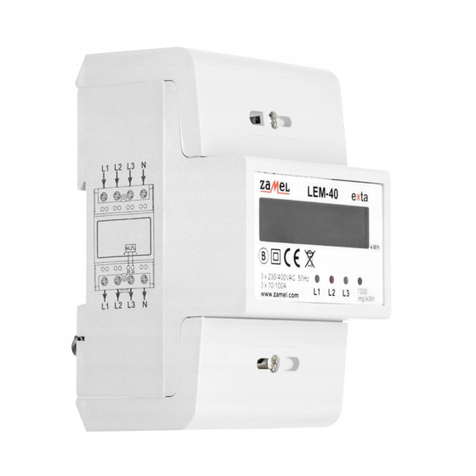
Zamel exta LEM-40 User manual

Zamel

Zamel exta LEM-40 User manual

Zamel exta LKM-02 User manual

Zamel

Zamel exta LKM-02 User manual

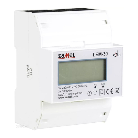
Zamel LEM-30 User manual

Zamel

Zamel LEM-30 User manual

Zamel Exta LKM-03 User manual

Zamel

Zamel Exta LKM-03 User manual

Zamel LKM - 01 User manual

Zamel

Zamel LKM - 01 User manual

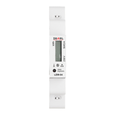
Zamel exta LEM-04 User manual

Zamel

Zamel exta LEM-04 User manual

Zamel LKM-03 User manual

Zamel

Zamel LKM-03 User manual

Popular Measuring Instrument manuals by other brands

Center 251 instruction manual

Center

Center 251 instruction manual

KPS KPS-CF100 instruction manual

KPS

KPS KPS-CF100 instruction manual

Rosemount 1199 Reference manual

Rosemount

Rosemount 1199 Reference manual

Chauvin Arnoux C.A 10101 manual

Chauvin Arnoux

Chauvin Arnoux C.A 10101 manual

Reichert AT550 user guide

Reichert

Reichert AT550 user guide

Max G Series Operational manual

Max

Max G Series Operational manual

Generac Power Systems PCRGM1 installation manual

Generac Power Systems

Generac Power Systems PCRGM1 installation manual

LumaSense 320 Series manual

LumaSense

LumaSense 320 Series manual

Konica Minolta SPECTRAMAGIC NX - instruction manual

Konica Minolta

Konica Minolta SPECTRAMAGIC NX - instruction manual

PCB Piezotronics IMI SENSORS TOM607A01 Installation and operating manual

PCB Piezotronics

PCB Piezotronics IMI SENSORS TOM607A01 Installation and operating manual

Eaton Moeller Series manual

Eaton

Eaton Moeller Series manual

TLV EF200F-C technical information

TLV

TLV EF200F-C technical information

Leica NA2 user manual

Leica

Leica NA2 user manual

TPS smartCHEM-C Handbook

TPS

TPS smartCHEM-C Handbook

Omega RHXL5SD user guide

Omega

Omega RHXL5SD user guide

Wozniak RC Tech KLW202 user manual

Wozniak RC Tech

Wozniak RC Tech KLW202 user manual

BIS VISTA operating manual

BIS

BIS VISTA operating manual

Nokeval PM10A manual

Nokeval

Nokeval PM10A manual

manuals.online logo
manuals.online logoBrands
  • About & Mission
  • Contact us
  • Privacy Policy
  • Terms and Conditions

Copyright 2025 Manuals.Online. All Rights Reserved.