POWER SUPPLY INDICATOR LKM-02 INSTRUCTION MANUAL
sp.j.
J.W. Dzida, K. Łodzińska
ul. Zielona 27, 43-200 Pszczyna, Poland
Tel. +48 (32) 210 46 65, Fax +48 (32) 210 80 04
VER. 001_18.09.2009
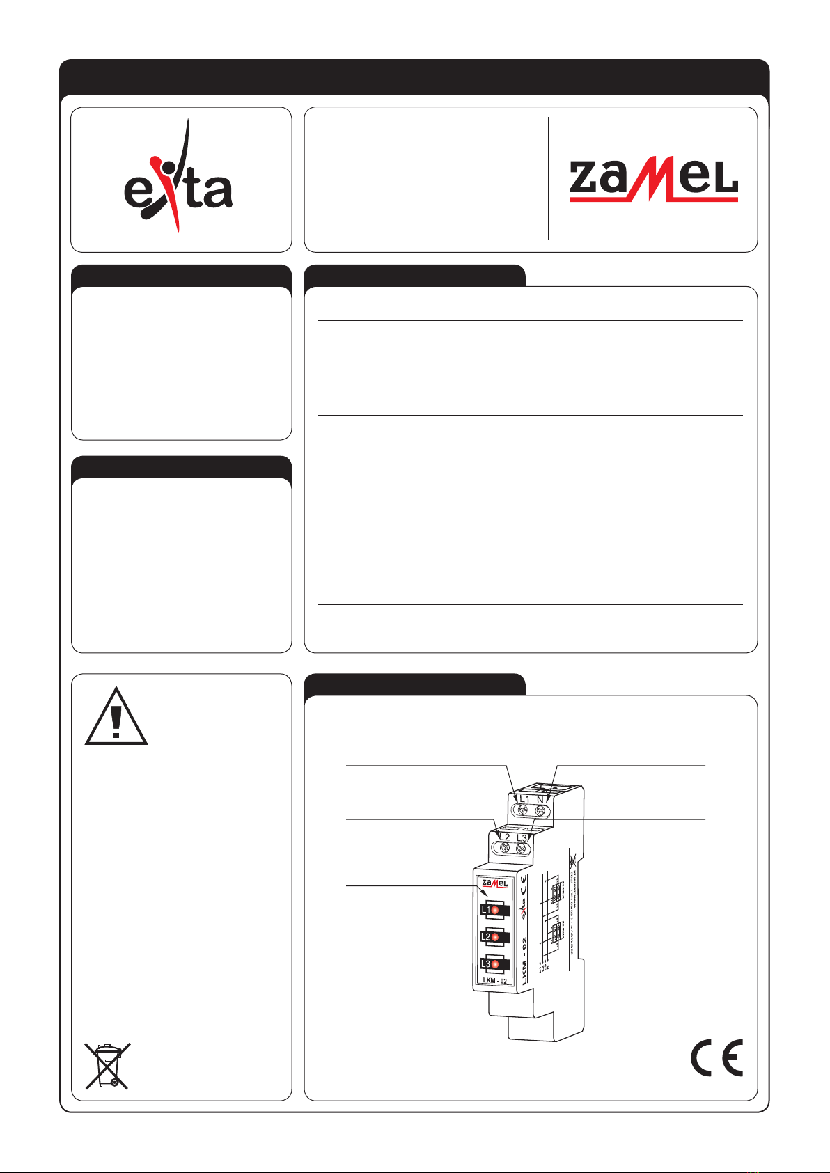
LKM-02
Power terminals: L1, L2, L3, N
Rated voltage: 230/400 V AC
Rated voltage tolerance: -15 ÷ +10 %
Rated frequency: 50 / 60 Hz
Rated current (type 10, 20, 30, 40): 3,6 / 9 / 4,8 / 6 mA
Power supply indicator: 3x LED
Number of terminal clamps: 4
Section of connecting cables: 0,2 ÷ 2,5 mm2
Ambient temperature range: -20 ÷ +45 oC
Operating position: freely
Mounting: rail TH 35 (PN-EN 60715)
Protection degree: IP20 (PN-EN 60529)
Protection level: II
Overvoltage category: II
Pollution degree: 2
Rated impulse withstand voltage: 1 kV (PN-EN 61000-4-5)
Dimensions: monomodular (17,5 mm) 90x17,5x66 mm
Weight: 0,050 kg
Reference standards: PN-EN 62094-1
PN-EN 61000-4-2,3,4,5,6,11
● Optical voltage presence signalling,
● LED diodes with increased light emis-
sion,
● long durability of lighting elements,
-
● easy adaptation for special use,
● monomodular casing,
● TH-35 DIN rail installation
.
The device is used to signal the pre-
sence of voltage in a three-phase supply
system. It is realized by means of three
LEDs (L1, L2, L3). There are four colours
of the LED diode available (red, green,
yellow and mixed). LKM-02 power supply
indicator can be used in the TN-C supply
system (with point zero), IT (without zero
point).
Power terminal (N)
Power terminal (L3)
Power terminal (L1)
Power terminal (L2)
Voltage indicators
The device is desi-
gned for three-pha-
se installation and
must be installed
in accordance with
standards valid in a
particular country.
The device should
be connected according to the details
included in this operating manual. In-
stallation, connection and control sho-
uld be carried out by a qualied elec-
trician staff, who act in accordance
with the service manual and the device
functions. Disassembling of the de-
vice is equal with a loss of guarantee
and can cause electric shock. Before
installation make sure the connection
cables are not under voltage. The cru-
ciform head screwdriver 3,5 mm should
be used to instal the device. Improper
transport, storage, and use of the device
inuence its wrong functioning. It is not
advisable to instal the device in the follo-
wing cases: if any device part is missing
or the device is damaged or deformed.
In case of improper functioning of the
device contact the producer.
The symbol means selective
collecting of electrical and electronical
equipment. It is forbidden to put
the used equipment together
with other waste


