POWER SUPPLY INDICATOR LKM - 01 INSTRUCTION MANUAL
FEATURES
TECHNICAL PARAMETERS
DESCRIPTION
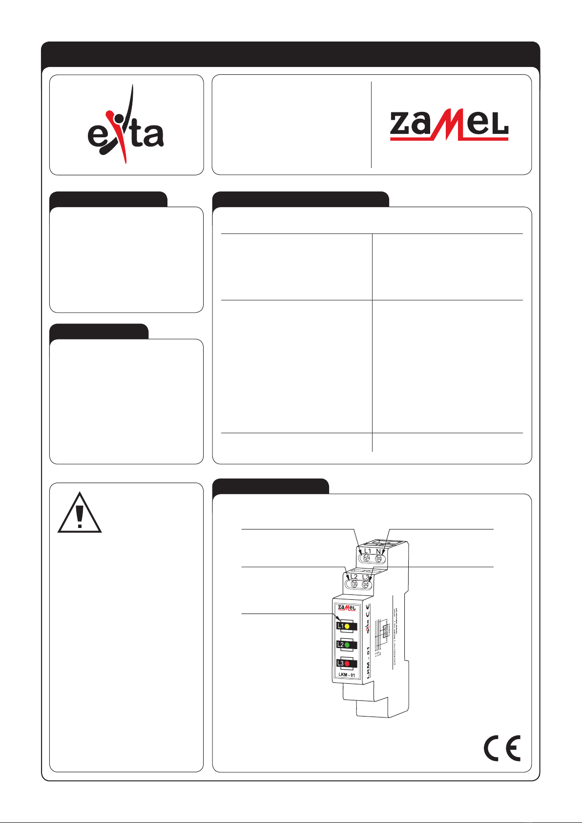
APPEARANCE
ver. 0.4.2 _ 2006.06.20_14:00
LKM - 01
Input (supply) terminals : L1, L2, L3, N
Input rated voltage: 230/400 V~
Input voltage tolerance: from -15 to +10 %
Rated frequency: 50 / 60 Hz
Rated power consumption (type 10, 20, 30, 40): 1,5 / 6 / 0,9 / 2,8 mA
Power supply indicator: 3x LED
Number of terminal clamps: 4
Section of connecting cables: from 0,2 to 2,5 mm2
Ambient temperature range: from -20 to +45 oC
Operating position: free
Mounting: TH35 rail (PN-EN 60715)
Protection degree: IP20 (PN-EN 60529)
Protection class: II
Overvoltage category: II
Pollution degree: 2
Rated impulse withstand voltage: 1 kV (PN-EN 61000-4-5)
Dimensions (height / width / depth): monomodular (17,5 mm) 90x17,5x66 mm
Weight: 47 g
Reference standards : PN-EN 62094-1
PN-EN 61000-4-2,3,4,5,6,11
یOptical voltage presence signal-
ling,
یLED diodes with increased light
emission,
یlong durability of lighting ele-
ments,
یeasy adaptation for special use,
یmonomodular casing,
یTH-35 DIN rail installation.
The device is used to signal the
presence of voltage in a three-phase
supply system. It is realized by means
of three LEDs (L1, L2, L3). There are
four colours of the LED diode available
(red, green, yellow and mixed). LKM-01
power supply indicator can be used in
the TN-C supply system (together with
point zero).
Input (supply) terminals (N)
Input (supply) terminals (L3)
Input (supply) terminals (L1)
Input (supply) terminals (L2)
Voltage indicator
ZAMEL Sp. z o.o.
ul. Zielona 27, 43-200 Pszczyna, Poland
Tel. +48 (32) 210 46 65, Fax +48 (32) 210 80 04
The device is desig-
ned for three-phase in-
stallation and must be
installed in accordance
with standards valid
in a particular country.
The device should be
connected according to the details
included in this operating manual.
Installation, connection and control
should be carried out by a qualied
electrician staff, who act in accordan-
ce with the service manual and the
device functions. Disassembling of
the device is equal with a loss of gua-
rantee and can cause electric shock.
Before installation make sure the con-
nection cables are not under voltage.
The cruciform head screwdriver 3,5
mm should be used to instal the devi-
ce. Improper transport, storage, and
use of the device inuence its wrong
functioning. It is not advisable to instal
the device in the following cases: if
any device part is missing or the de-
vice is damaged or deformed. In case
of improper functioning of the device
contact the producer.
CAUTION


