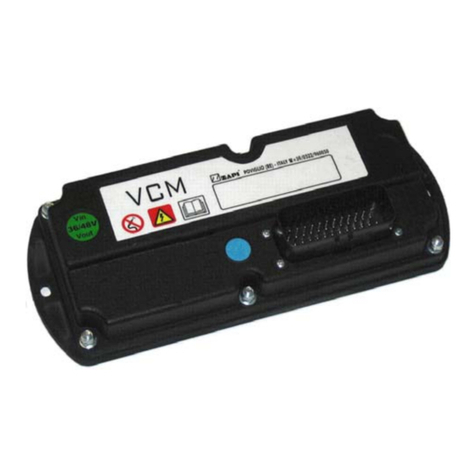
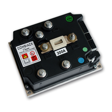
Zapi ACE0 2mC User manual

ELECTRONIC • OLEODYNAMIC • INDUSTRIAL
EQUIPMENTS CONSTRUCTION
Via Parma, 59 – 42028 – POVIGLIO (RE) – ITALY
Tel +39 0522 960050 (r.a.) – Fax +39 0522 960259
User Manual
ACE0 2µC
COMBIAC0 2µC
Publication: AF6ZP0CA
Edition: March 1, 2018
EN

Page – 2/155 AF6ZP0CA – COMBIAC0 & ACE0 2uC – User Manual
Copyright © 1975-2018 Zapi S.p.A.
All rights reserved
Contents of this publication are a ZAPI S.p.A. property; all related authorizations are covered by
Copyright. Any partial or total reproduction is prohibited.
Under no circumstances will Zapi S.p.A. be held responsible to third parties for damage caused
by the improper use of the present publication and of the device/devices described in it.
Zapi spa reserves the right to make changes or improvements to its products at any time and
without notice.
The present publication reflects the characteristics of the product described at the moment of
distribution. The publication therefore does not reflect any changes in the characteristics of the
product as a result of updating.
is a registered trademark property of Zapi S.p.A.
NOTES DEFINITIONS
4This symbol is used in this publication to indicate an annotation or a suggestion
you should pay attention to.
UThis symbol is used inside this publication to indicate an action or a
characteristic very important for security. Pay special attention to the
annotations pointed out with this symbol.

AF6ZP0CA – COMBIAC0 & ACE0 2uC – User Manual Page – 3/155
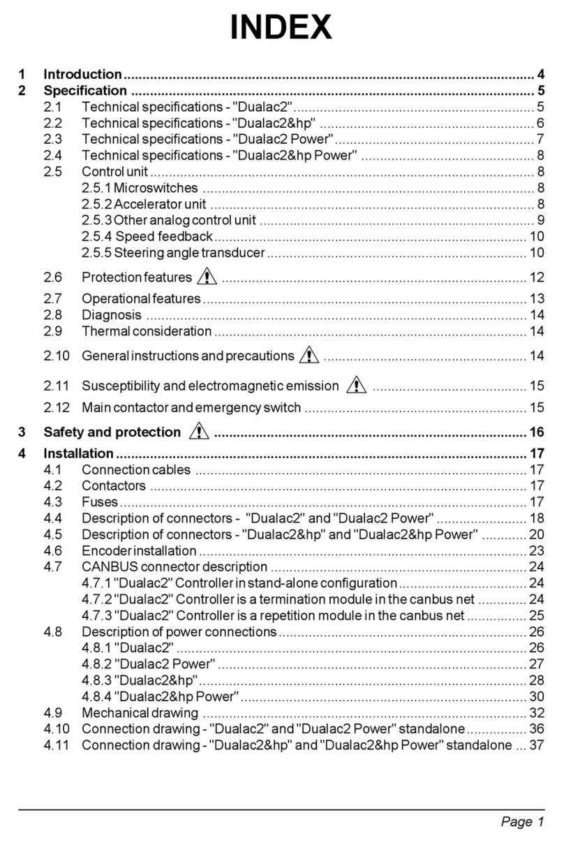
Contents
1INTRODUCTION ...................................................................................................................6
1.1About this document ...................................................................................................6
1.1.1Scope of this manual ....................................................................................6
1.1.2Manual revision.............................................................................................6
1.1.3Warnings and notes......................................................................................6
1.2About the controller.....................................................................................................7
1.2.1Safety............................................................................................................7
1.2.2OEM’s Responsibility ....................................................................................7
1.2.3Technical support..........................................................................................7
2SPECIFICATIONS.................................................................................................................8
2.1General features .........................................................................................................8
2.2Technical specifications..............................................................................................8
2.3Current ratings ............................................................................................................9
2.4Voltage ratings..........................................................................................................10
3DRAWINGS.........................................................................................................................11
3.1Mechanical drawings ................................................................................................11
3.1.1Base plate version ......................................................................................11
3.1.2Longitudinal heat sink version.....................................................................12
3.2Connection drawings ................................................................................................13
3.2.1AC Traction configuration ...........................................................................13
3.2.2AC Pump configuration ...............................................................................14
3.2.3AC CAN Open configuration .......................................................................15
3.2.4PMSM Traction configuration......................................................................16
3.2.5PMSM Pump configuration .........................................................................17
4I/O INTERFACE DESCRIPTION.........................................................................................18
4.1Power connectors .....................................................................................................18
4.2Ampseal connector ...................................................................................................18
4.3Internal connector .....................................................................................................21
4.4External devices .......................................................................................................22
4.4.1Key Input.....................................................................................................22
4.4.2Digital inputs ...............................................................................................22
4.4.3Analog inputs ..............................................................................................24
4.4.4Special inputs..............................................................................................25
4.4.5Encoder inputs............................................................................................25
4.4.6MC output ...................................................................................................26
4.4.7EB output ....................................................................................................28
4.4.8Auxiliary outputs..........................................................................................29
4.4.9High-side driver...........................................................................................31
4.4.10Motor temperature measurement input.......................................................32
4.4.11Sensor supply .............................................................................................32
4.4.12Analog supply .............................................................................................32
4.4.13CAN bus......................................................................................................33
5INSTALLATION HINTS.......................................................................................................34
5.1Material overview......................................................................................................34
5.1.1Connection cables ......................................................................................34
5.1.2Contactors...................................................................................................34
5.1.3Fuses ..........................................................................................................34

Page – 4/155 AF6ZP0CA – COMBIAC0 & ACE0 2uC – User Manual
5.2Installation of the hardware ...................................................................................... 35
5.2.1Positioning and cooling of the controller.....................................................35
5.2.2Wirings: CAN bus connections and possible interferences ........................ 36
5.2.3Wirings: I/O connections............................................................................. 38
5.2.4Connection of an encoder .......................................................................... 39
5.2.5Connection of a sin/cos sensor ..................................................................40
5.2.6Connection of Hall sensors......................................................................... 40
5.2.7Connection of main contactor and key switch ............................................41
5.2.8Insulation of the truck frame .......................................................................41
5.3EMC .........................................................................................................................42
5.4Various suggestions .................................................................................................43
6FEATURES.........................................................................................................................44
6.1Operational features................................................................................................. 44
6.2Dual traction motor ................................................................................................... 45
6.3Pump motor.............................................................................................................. 45
6.4Torque mode ............................................................................................................45
6.5Speed mode ............................................................................................................. 45
6.6Protection and safety features.................................................................................. 45
6.6.1Protection features .....................................................................................45
6.6.2Safety features ...........................................................................................46
7START-UP HINTS...............................................................................................................47
7.1Check prior to initial power up .................................................................................. 47
7.2Configuring motor controller for the application........................................................ 47
7.3Set-up procedure for AC traction inverter.................................................................48
7.3.1Sin/cos-sensor case ...................................................................................48
7.4Set-up procedure for AC pump inverter....................................................................49
8PROGRAMMING & ADJUSTEMENTS ..............................................................................51
8.1Settings overview .....................................................................................................52
8.2Settings description ..................................................................................................53
8.2.1PARAMETER CHANGE............................................................................. 53
8.2.2SET OPTIONS ........................................................................................... 59
8.2.3ADJUSTMENTS ......................................................................................... 67
8.2.4SPECIAL ADJUST. .................................................................................... 72
8.2.5HARDWARE SETTING .............................................................................. 75
8.3TESTER function......................................................................................................77
8.3.1TESTER – Master microcontroller..............................................................77
8.3.2TESTER – Supervisor microcontroller........................................................ 85
9OTHER FUNCTIONS..........................................................................................................87
9.1PROGRAM VACC function ...................................................................................... 87
9.2PROGRAM LIFT / LOWER function......................................................................... 87
9.3PROGRAM STEER function .................................................................................... 88
9.4Acceleration time ...................................................................................................... 88
9.5Braking time ............................................................................................................. 89
9.6Acceleration smoothness ......................................................................................... 91
9.7Steering curve ..........................................................................................................91
9.8Description of the throttle regulation......................................................................... 92
9.9NMC & NEB output ..................................................................................................93
9.10Battery-charge detection ..........................................................................................94
9.11EVP Setup................................................................................................................ 95

AF6ZP0CA – COMBIAC0 & ACE0 2uC – User Manual Page – 5/155
9.12Torque Profile ...........................................................................................................97
9.13Steering Table ..........................................................................................................99
9.14Motor thermal protection.........................................................................................100
10DIAGNOSTIC SYSTEM.....................................................................................................101
10.1ALARMS menu .......................................................................................................101
10.2Diagnoses...............................................................................................................101
10.3Alarms from master µC...........................................................................................103
10.3.1Troubleshooting of alarms from master µC...............................................107
10.4Alarms from supervisor µC .....................................................................................131
10.4.1Troubleshooting of alarms from supervisor µC.........................................131
10.5Info code for electrovalves......................................................................................136
11SPARE PARTS .................................................................................................................137
12PERIODIC MAINTENANCE..............................................................................................138
13APPENDICES....................................................................................................................139
13.1Appendix A: PC CAN Console user guide..............................................................139
13.1.1PC CAN Console configuration.................................................................139
13.1.2Parameter download.................................................................................141
13.1.3How to modify the parameters ..................................................................142
13.1.4Program Vacc ...........................................................................................143
13.1.5Lift & Lower command acquiring
...............................................................143
13.1.6Steer acquiring..........................................................................................144
13.1.7Tester Functionality...................................................................................144
13.1.8Alarm Logbook..........................................................................................145
13.2Appendix B: Zapi Smart Console user guide..........................................................146
13.2.1Operational Modes....................................................................................146
13.2.2The keyboard............................................................................................146
13.2.3Home Screen ............................................................................................147
13.2.4Connected.................................................................................................148
13.2.5How to modify a parameter.......................................................................149
13.2.6Program VACC .........................................................................................150
13.2.7Lift and Lower commands acquiring .........................................................151
13.2.8Steer command acquiring.........................................................................152
13.2.9Tester........................................................................................................152
13.2.10Alarms.......................................................................................................152
13.2.11Download parameter list to USB stick.......................................................153
APPROVAL SIGNS
COMPANY FUNCTION INITIALS SIGN
PROJECT MANAGER
TECHNICAL ELECTRONIC
MANAGER VISA
SALES MANAGER VISA

Page – 6/155 AF6ZP0CA – COMBIAC0 & ACE0 2uC – User Manual
1 INTRODUCTION
1.1 About this document
1.1.1 Scope of this manual
This manual provides important information about ACE0/COMBIAC0 controller: It
presents instructions, guidelines and diagrams related to installation and
maintenance of the controller in an electrically powered vehicle.
1.1.2 Manual revision
This revision replaces all previous revisions of this document. Zapi has put much
effort to ensure that this document is complete and accurate at the time of
printing. In accordance with Zapi policy of continuous product improvement, all
data in this document are subject to change or correction without prior notice.
1.1.3 Warnings and notes
In this manual, special attention must be paid to information presented in warning
and information notices.
Definitions of warning and information notices are the following.
4This is an information box, useful for anyone is working on the installation, or for
a deeper examination of the content.
UThis is a warning box, it can describe:
- operations that can lead to a failure of the electronic device or can be
dangerous or harmful for the operator;
- items which are important to guarantee system performance and safety.
UThis is a further warning within the box. Pay special attention to the
annotations pointed out within warning boxes.

AF6ZP0CA – COMBIAC0 & ACE0 2uC – User Manual Page – 7/155
1.2 About the controller
1.2.1 Safety
Zapi provides this and other manuals to assist manufacturers in using the motor
controller in a proper, efficient and safe manner. Manufacturers must ensure that
all people responsible for the design and use of equipment employing the motor
controller have the proper professional skills and equipment knowledge.
UBefore doing any operation, ensure that the battery is disconnected and
when the installation is completed start the machine with the drive wheels
raised from the ground to ensure that any installation error does not
compromise safety.
UAfter the inverter turn-off, even with the key switch open, the internal
capacitors may remain charged for some time. For safe operation onto the
setup, it is recommended to disconnect the battery and to discharge the
capacitors by means of a resistor of about 10 – 100 Ohm between +B and -
B terminals of the inverter.
1.2.2 OEM’s Responsibility
Zapi motor controllers are intended for controlling motors in electric vehicles.
These controllers are supplied to original equipment manufacturers (OEMs) for
incorporation into their vehicles and vehicle control systems.
Electric vehicles are subject to national and international standards of
construction and operation which must be observed. It is responsibility of the
vehicle manufacturer to identify the correct standards and to ensure that the
vehicle meets these standards. As a major electrical control component, the role
of a Zapi motor controller should be carefully considered and relevant safety
precautions taken. It has several features which can be configured to help the
system integrator meeting vehicle safety standards.
Zapi does not accept responsibility for incorrect application of its products.
1.2.3 Technical support
For additional information on any topic covered in this document or application
assistance on other Zapi products, contact Zapi sales department.

Page – 8/155 AF6ZP0CA – COMBIAC0 & ACE0 2uC – User Manual
2 SPECIFICATIONS
2.1 General features
COMBIAC0/ACE0 inverters are controllers designed to control AC induction,
BLDC and PMSM motors, in the range from 2 kW to 5 kW continuous power,
used in a variety of battery-powered material handling trucks.
COMBIACE0 is designed to control series-wound DC motors too, typically
employed as pump motor; AC and DC sections are combined in the same device.
Typical applications include, but are not limited to: walkie trucks and rider pallet
trucks, stackers, low level order pickers, small counterbalanced trucks, aerial-
access equipment.
The main inverter features are:
16-bits microcontroller for motor control and main functions, 576+ kByte
embedded flash memory.
16-bits microcontroller for safety functions, 320+ kByte embedded flash
memory.
Controller for AC motors from 2 kW to 5 kW.
Pump controller for series-wound DC motors (only for COMBIAC0).
Field-oriented motor control.
Smooth low-speed control and zero-speed holding control.
Zapi patented sensorless and sense-coil control.
Driver for a line contactor.
Low-side and high-side drivers for an electromechanical brake (short
circuit protected).
Drivers for PWM voltage-controlled electrovalves and for two proportional
valves (PWM current controlled).
Short-circuit and open-load protection.
Thermal cutback, warnings and automatic shutdown for protection of
motor and controller.
ESD-protected CAN bus interface.
Software downloadable via serial link (internal connector) or CAN bus
(external connector).
Diagnostic provided via CAN bus using Zapi PC CAN Console.
Rugged sealed housing and connectors meet IP65 environmental sealing
standards for use in harsh environments.
2.2 Technical specifications
Motor type:.......................................induction AC, synchronous AC, brushless DC
Control mode: ..................................................................... speed or torque control
Operating frequency of the AC inverter: .........................................................8 kHz
Operating frequency of the DC chopper (COMBIAC0 only): ........................16 kHz
Ambient operating temperature range: .............................................-40 °C ÷ 40 °C
Ambient storage temperature range: ................................................-40 °C ÷ 85 °C
Maximum inverter temperature (at full power): ...............................................85 °C
Connector: .................................................................................... 35-pins Ampseal
Package environmental rating: .........................................................................IP65

AF6ZP0CA – COMBIAC0 & ACE0 2uC – User Manual Page – 9/155
2.3 Current ratings
Model Nominal DC
voltage
Maximum
2-min rated
current [Arms]
Continuous
rated current
[Arms]
DC maximum
current [A]
ACE0
24V 220 110
-
36/48V 180 90
COMBIAC0
24V 220 110 270
36/48V 180 90 220
ACE0 PW
24V 320 160
-
36/48V 280 140
36/48V 320 140
80V 200 100
COMBIAC0 PW
24V 320 160 400
36/48V 280 140 300
36/48V 320 140 300
80V 200 100 200
4Combinations of DC choppers and 3-phase inverters different from those
reported in the previous table are also available.
4Internal algorithms automatically reduce the maximum current limit when heat
sink temperature is above 85°C. Heat sink temperature is measured internally
near the power MOSFETs (see paragraph 6.6).
4Two-minute ratings are referred to an inverter equipped with a base plate. No
additional external heat sink or fans are used for the 2-minute rating test. Ratings
are based on an initial controller base plate temperature of 40°C and a maximum
base plate temperature of 85°C.
4The inverter can deliver the rated continuous current only if it is adequately
cooled. When it is equipped with its own finned heat sink, a proper dissipation is
obtained by applying a 100 m3/h airflow. In case it is provided with the base plate,
it is customer’s duty to design an adequate cooling system that can dissipate the
heat produced by the inverter, keeping its temperature below 85 °C. Otherwise,
the inverter will deliver a continuous RMS current lower than the rated one.

Page – 10/155 AF6ZP0CA – COMBIAC0 & ACE0 2uC – User Manual
2.4 Voltage ratings
Nominal DC voltage 24V 36/48V 80V
Conventional working voltage range 19.2 V ÷ 28.8 V 28.8 V ÷ 57.6 V 57.8 V ÷ 96 V
Non-operational overvoltage limits 35V 65V 115V
Non-operational undervoltage limits 10V 10V 30V
4Conventionally, the controller can be set to operate without alarm in the range
from 80% to 120% of the nominal battery voltage. With a different DC voltage
than specified, the controller raises an alarm.
4Undervoltage and overvoltage thresholds are defined by hardware. After start-up,
controller is fully operative if the supply voltage stays within these limits.
4Undervoltage is evaluated on the KEY input (A10); overvoltage is evaluated on
the positive battery terminal +B.

AF6ZP0CA – COMBIAC0 & ACE0 2uC – User Manual Page – 11/155
3 DRAWINGS
3.1 Mechanical drawings
3.1.1 Base plate version
0.5 X 45°
R 1
1:2 A3
COMBIAC0 AMPSEAL FRAMELESS DIMENSIONS
1/1 AS
26/05/15
AF6ZP7AA

Page – 12/155 AF6ZP0CA – COMBIAC0 & ACE0 2uC – User Manual
3.1.2 Longitudinal heat sink version
0.5 X 45°
R 1
1:2 A3
COMBIAC0 AMPSEAL FRAMELESS LONGITUDINAL HEAT SINK DIMENSIONS
1/1 AS
26/05/15
AF6ZP7BA

AF6ZP0CA – COMBIAC0 & ACE0 2uC – User Manual Page – 13/155
3.2 Connection drawings
3.2.1 AC Traction configuration

Page – 14/155 AF6ZP0CA – COMBIAC0 & ACE0 2uC – User Manual
3.2.2 AC Pump configuration

AF6ZP0CA – COMBIAC0 & ACE0 2uC – User Manual Page – 15/155
3.2.3 AC CAN Open configuration

Page – 16/155 AF6ZP0CA – COMBIAC0 & ACE0 2uC – User Manual
3.2.4 PMSM Traction configuration

AF6ZP0CA – COMBIAC0 & ACE0 2uC – User Manual Page – 17/155
3.2.5 PMSM Pump configuration

Page – 18/155 AF6ZP0CA – COMBIAC0 & ACE0 2uC – User Manual
4 I/O INTERFACE DESCRIPTION
4.1 Power connectors
Power connections are on vertical posts where to bolt power-cables lugs. On the
cover of the converter they are labeled as:
Terminal name Description
+B Positive battery termination
-B Negative battery termination
U, V, W Motor phase terminations.
-P Negative terminal of pump DC motor (COMBIAC0 only).
In combination with COMBIAC0, DC pump motor must be connected between
terminals +B and -P. PWM frequency at -P is 16 kHz. Terminal -P is protected by
short circuit detection, voltage and current measurements. Freewheeling diodes
to +B are built in (MOSFETs internal diodes).
4.2 Ampseal connector
Inverter is equipped with a 35-poles Ampseal connector like that of the figure.
Each of the 35 pins is referred to as “A#”, where “A” denotes the connector name
and “#” the pin number, from 1 to 35.
35-poles Ampseal connector.
The following table lists the functional associations for the pins of the 35-poles
Ampseal connector.
4For each I/O pin, the default Zapi function is indicated. The function of each pin
can be changed in customized software.
4Some I/O pins can have special functionalities depending on the controller
configuration.

AF6ZP0CA – COMBIAC0 & ACE0 2uC – User Manual Page – 19/155
Pin Type Name Description
A1 Input DI0
Digital input DI0.
The input is activated when it is connected to +B. With the logic
hardware properly configured it can be used to supply the positive
terminals of EB and MC.
The default function is as TILLER input.
A2 Output PEB Positive supply of the electromechanical brake. For the 24V
version only, it is supplied through a high-side driver.
A3 Input PEV
Positive supply of electrovalves: EV1, EV2, EV3, EV4, EV5,
EVP1, EVP2, HORN. With the hardware properly configured, it
can be used to supply the positive terminal of EB.
This input is to be supplied with positive voltage taken after main
contactor.
A4 Output NEB Driving output for the electromechanical brake (driving to -B);
PWM controlled; 2 A maximum continuous current.
A5 Output NENC
Negative supply for external devices (encoder, potentiometers,
etc.)
A6 Input DI2
Digital input DI2.
The input is activated when the external switch is closed.
By default, if HARD & SOFT option is ON (see 8.2.2Errore.
L'origine riferimento non è stata trovata.), the H&S function is
activated when the switch is closed.
A7 Input DI1
Digital input DI1. Active high.
The input is activated when it is connected to +B.
The default function is as QI/PB input (quick inversion/pedal
brake). Closing the switch quick inversion function is activated.
A8 Output EV 5 /
PPOT
Driving output for the on/off electrovalve EV5; 1 A maximum
continuous current (driving to -B).
Depending on internal jumper configuration it can be used as
positive supply for external devices (+12V/+5V, max150 mA).
A9 Output EV1 Driving output for the on/off electrovalve EV1 (driving to -B); 1 A
maximum continuous current.
A10 Input KEY Input of the key switch signal.
A11 Output EV2 Driving output for the PWM voltage-controlled electrovalve EV2
(driving to -B); 1 A maximum continuous current.
A12 Output NMC Driving output for the main contactor (driving to -B); PWM voltage-
controlled; 1 A maximum continuous current.
A13 Input ENCB Phase B of the traction motor encoder.
A14 Input ENCA Phase A of the traction motor encoder.

Page – 20/155 AF6ZP0CA – COMBIAC0 & ACE0 2uC – User Manual
Pin Type Name Description
A15 Input CPOT1
Analog input 1.
The default function is as accelerator reference (wiper contact of
the accelerator potentiometer).
A16 Input DI10
Digital input DI10.
The input is activated when it is connected to +B.
The default function is as 2ND input, closing the switch valve EV2
is activated.
A17 Input DI8
Digital input DI8.
The input is activated when it is connected to +B.
The default function is as 1ST input, closing the switch valve EV1
is activated.
A18 Input DI11 /
CPOT3
Digital input DI11.
The input is activated when the external switch is closed to -B.
The default function is as CUTBACK SPEED 1 input.
In the sense coil version, this input is connected to the AC motor
sense coil.
Hardware can be properly configured as additional analog or
digital input.
A19 Input DI5
Digital input DI5.
The input is activated when it is connected to +B.
The default function is as HORN input. Closing the switch, the
horn is activated.
A20 Input DI6
Digital input DI6.
The input is activated when it is connected to +B.
The default function is as LOWERING input.
A21 Input DI12 /
CPOT4
Digital input DI12.
The input is activated when the external switch is closed to -B.
The default function is as CUTBACK SPEED 2 input.
In the sense coil version, this input is connected to the AC motor
sense coil.
Hardware can be properly configured as additional analog or
digital input.
A22 Input PTH
Analog input for the thermal sensor of the traction motor.
Internal pull-up consists of a fixed 2 mA (max 5 V) current source.
A23 Output EVP2 Driving output for the second PWM current-controlled electrovalve
(driving to -B).
A24 Output EVP1
Driving output for the first PWM current-controlled electrovalve
(driving to -B).
Default function is as LOWERING valve.
A25 Output PENC
Positive supply for external devices (encoder, potentiometers,
etc.) +12 /+5 V, 150 mA maximum.
A26 Output HORN Driving output for the horn electrovalve (driving to -B). Protected.
This manual suits for next models
1
Table of contents
Other Zapi Inverter manuals
Popular Inverter manuals by other brands

Airpax Dimensions
Airpax Dimensions MIL-24/2600Q owner's manual

Minarik
Minarik MM30000 Series user manual

SolaX Power
SolaX Power X3 Hybrid Series user manual

DORNA TECHNOLOGY
DORNA TECHNOLOGY DLM1-0D40S2G user manual

Scientific Aviation
Scientific Aviation SOOFIE installation guide

Uniteck
Uniteck UNIPOWER 200.12 DC manual