AFDZP0BA – VCM Zapi 2uC - User Manual Page - 3/54
Contents
1INTRODUCTION ...................................................................................................................5
2SPECIFICATION...................................................................................................................7
2.1Technical specifications VCM Standard .....................................................................7
2.2Technical specifications VCM Premium ....................................................................7
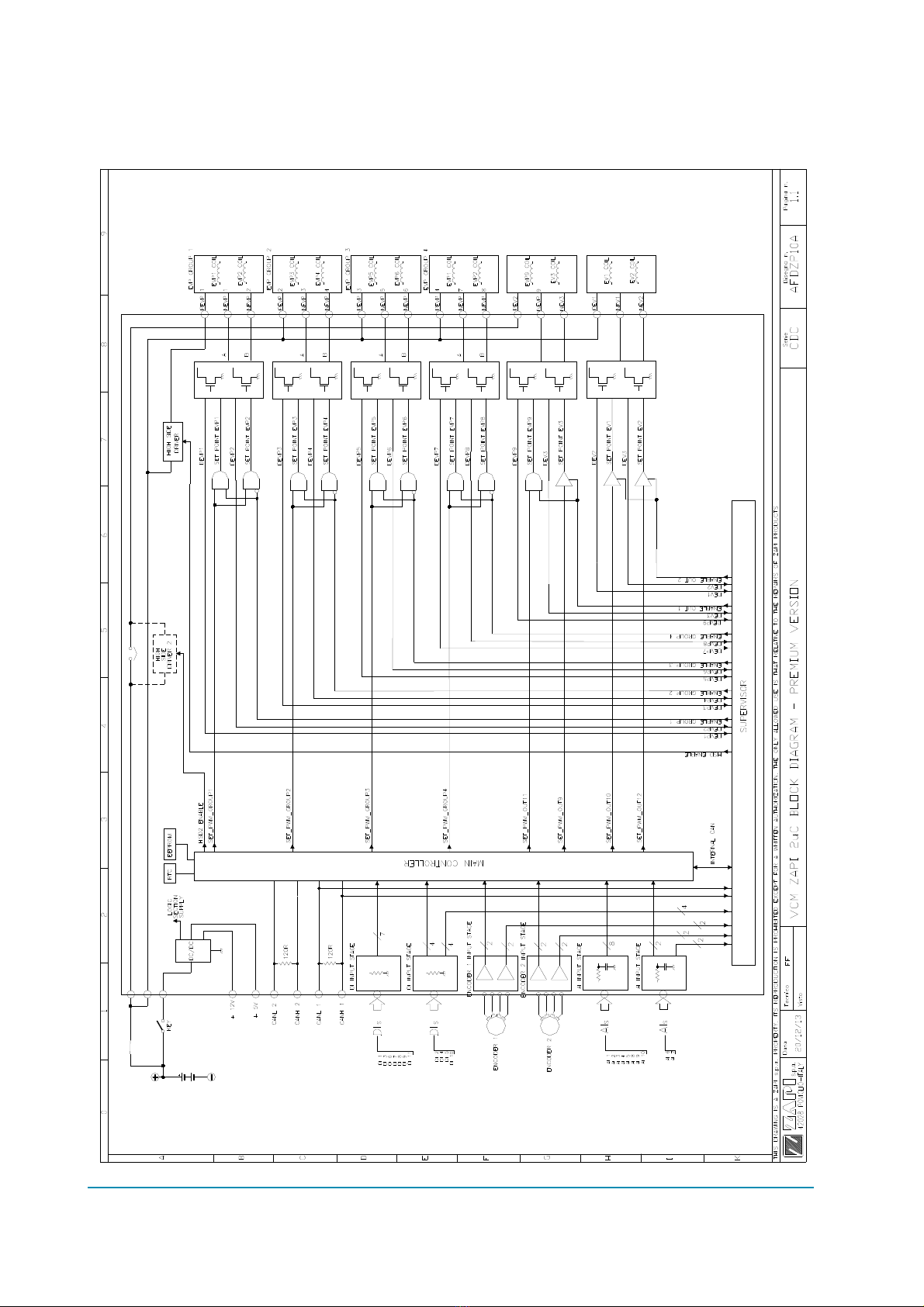
3BLOCK DIAGRAM................................................................................................................8
4SPECIFICATION FOR THE I/O INTERACES.......................................................................9
4.1Digital inputs ...............................................................................................................9
4.1.1DI1 ÷ DI11 technical details ..........................................................................9
4.1.2Microswitches ...............................................................................................9
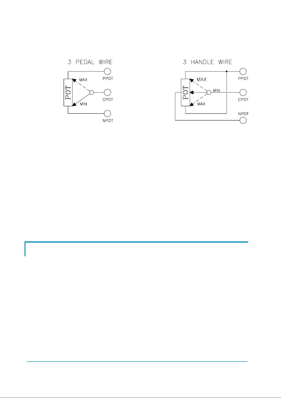
4.2Analog inputs ..............................................................................................................9
4.3Outputs .....................................................................................................................10
4.4Incremental encoder .................................................................................................11
4.5CAN BUS..................................................................................................................12
5ADDITIONAL FEATURES ..................................................................................................14
5.1Real Time Clock .......................................................................................................14
5.2High Side Driver........................................................................................................14
6INSTALLATION HINTS.......................................................................................................15
6.1Material overview......................................................................................................15
6.1.1Connection cables ......................................................................................15
6.1.2Fuses ..........................................................................................................15
6.2Installation of the hardware.......................................................................................15
6.2.1Wirings: CAN connections and possible interferences ...............................16
6.2.2Wirings: I/O connections .............................................................................18
6.2.3Insulation of truck frame..............................................................................18
6.3Protection features....................................................................................................18
6.3.1Hardware Protection ...................................................................................18
6.3.2Safety Features...........................................................................................18
6.3.3Double microcontroller architecture ............................................................19
6.4EMC..........................................................................................................................19
7DESCRIPTION OF THE CONNECTORS............................................................................21
7.1CNA Ampseal 35 poles.............................................................................................21
7.2CNB Ampseal 23 poles (only for VCM PREMIUM) ..................................................23
8DRAWINGS.........................................................................................................................24
8.1Mechanical drawing ..................................................................................................24
8.1.1VCM STANDARD .......................................................................................24
8.1.2VCM PREMIUM ..........................................................................................25
8.2Functional drawing....................................................................................................26
8.2.1VCM STANDARD .......................................................................................26
8.2.2VCM PREMIUM ..........................................................................................27
9PROGRAMMING & ADJUSTMENTS .................................................................................28
9.1Description of programmable functions ....................................................................28
9.2Description of the TESTER function .........................................................................35
9.3Description of the console SAVE function ................................................................37
9.4Description of the console RESTORE function ........................................................38
9.5Description of the throttle regulation .........................................................................38
9.6Description of the battery charge detection setting...................................................39
9.7Description of ALARMS menu ..................................................................................40