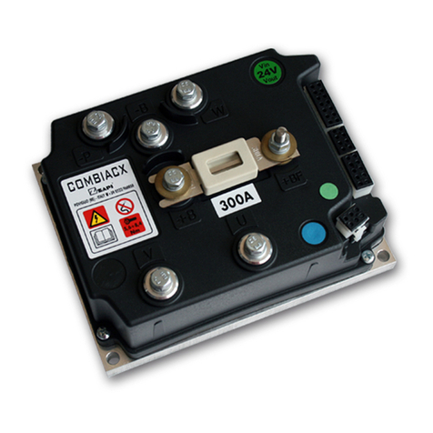
Zapi ACE3 User manual

ELECTRONIC • OLEODYNAMIC • INDUSTRIAL
EQUIPMENTS CONSTRUCTION
Via Parma, 59 – 42028 – POVIGLIO (RE) – ITALY
Tel +39 0522 960050 (r.a.) – Fax +39 0522 960259
EN
User Manual
ACE3
INVERTER
Publication N°: AFFZP0BB
Edition: 08 May 2017

Page – 2/139 AFFZP0BB – ACE3 – User Manual
Copyright © 1975-2017 Zapi S.p.A.
All rights reserved
Contents of this publication are a ZAPI S.p.A. property; all related authorizations are covered by
Copyright. Any partial or total reproduction is prohibited.
Under no circumstances will Zapi S.p.A. be held responsible to third parties for damage caused by
the improper use of the present publication and of the device/devices described in it.
Zapi spa reserves the right to make changes or improvements to its products at any time and
without notice.
The present publication reflects the characteristics of the product described at the moment of
distribution. The publication therefore does not reflect any changes in the characteristics of the
product as a result of updating.
is a registered trademark property of Zapi S.p.A.
NOTES DEFINITIONS
4This symbol is used in this publication to indicate an annotation or a suggestion you
should pay attention to.
UThis symbol is used inside this publication to indicate an action or a
characteristic very important for security. Pay special attention to the
annotations pointed out with this symbol.

AFFZP0BB – ACE3 – User Manual Page – 3/139
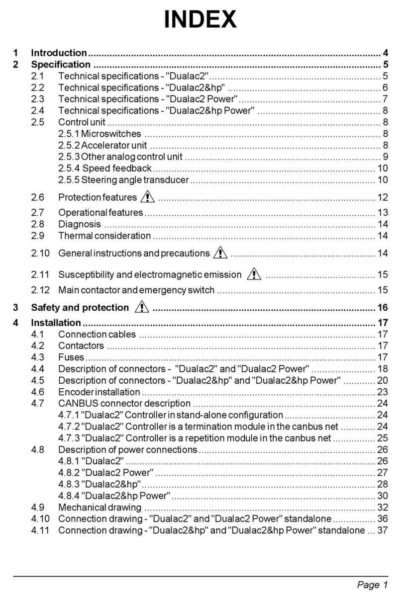
Contents
1INTRODUCTION...................................................................................................................7
1.1About this document................................................................................................... 7
1.1.1Scope of this manual ....................................................................................7
1.1.2Manual revision ............................................................................................ 7
1.1.3Warnings and notes...................................................................................... 7
1.2About the Controller ...................................................................................................8
1.2.1Safety ...........................................................................................................8
1.2.2OEM’s Responsibility....................................................................................8
1.2.3Technical Support......................................................................................... 8
2SPECIFICATIONS ................................................................................................................9
2.1General features......................................................................................................... 9
2.2Technical specifications of ACE3 ............................................................................. 10
2.3Technical specifications of ACE3 Power.................................................................. 10
2.4Functional features...................................................................................................11
2.5Diagnoses ................................................................................................................12
3DRAWINGS.........................................................................................................................13
3.1Mechanical drawing – ACE3 / ACE3 Power.............................................................13
3.2Connection drawing – ACE3 Traction Standard.......................................................14
3.3Connection drawing – ACE3 Traction Premium....................................................... 15
3.4Connection drawing – ACE3 Pump Standard ..........................................................16
3.5Connection drawing – ACE3 Pump Premium........................................................... 17
4DESCRIPTION OF THE CONNECTORS ...........................................................................18
4.1Power connectors.....................................................................................................18
4.2Ampseal connectors.................................................................................................18
4.2.1ACE3 Traction Standard............................................................................. 19
4.2.2ACE3 Pump Standard ................................................................................ 20
4.2.3ACE3 Traction Premium............................................................................. 21
4.2.4ACE3 Pump Premium ................................................................................ 23
5INPUT DEVICES.................................................................................................................25
5.1Key Input ..................................................................................................................25
5.1.1Function...................................................................................................... 25
5.1.2Protection ...................................................................................................25
5.2Digital Inputs............................................................................................................. 25

Page – 4/139 AFFZP0BB – ACE3 – User Manual
5.2.1Microswitches ............................................................................................. 25
5.3Accelerator unit ........................................................................................................ 26
5.4Other analog control unit .......................................................................................... 27
5.4.1Standard version ........................................................................................ 27
5.4.2Premium version......................................................................................... 27
5.5Speed feedback ....................................................................................................... 27
5.5.1Sin/Cos sensor and Hall sensors ............................................................... 28
6INSTALLATION HINTS ......................................................................................................29
6.1Material overview ..................................................................................................... 29
6.1.1Connection cables ...................................................................................... 29
6.1.2Contactors ..................................................................................................29
6.1.3Fuses.......................................................................................................... 29
6.2Hardware installation................................................................................................30
6.2.1Positioning and cooling of the controller.....................................................30
6.2.2Wirings: power cables ................................................................................ 30
6.2.3Wirings: CAN bus connections and possible interferences ........................ 31
6.2.4Wirings: I/O connections............................................................................. 33
6.2.5Connection of the encoder ......................................................................... 33
6.2.6Connection of a Sin/Cos sensor ................................................................. 34
6.2.7Connection of Hall sensors......................................................................... 35
6.2.8Main-contactor and key connection............................................................ 35
6.2.9Insulation of truck frame .............................................................................36
6.3Protection and safety features.................................................................................. 36
6.3.1Protection features .....................................................................................36
6.3.2Safety Features ..........................................................................................37
6.4EMC .........................................................................................................................37
6.5Various suggestions .................................................................................................39
7INVERTER SETTINGS .......................................................................................................40
7.1Settings overview .....................................................................................................40
7.2Settings description ..................................................................................................41
7.2.1PARAMETER CHANGE............................................................................. 41
7.2.2SET OPTIONS ........................................................................................... 45
7.2.3ADJUSTMENT ........................................................................................... 53
7.2.4SPECIAL ADJUST. .................................................................................... 58

AFFZP0BB – ACE3 – User Manual Page – 5/139
7.2.5HARDWARE SETTING .............................................................................. 61
7.2.6HYDRO SETTING ...................................................................................... 62
7.3TESTER function......................................................................................................63
7.3.1Master microcontroller ................................................................................ 63
7.3.2Supervisor microcontroller.......................................................................... 69
7.4Set-up procedure for traction inverter.......................................................................70
7.4.1Sin/cos-sensored case ...............................................................................71
7.5Set-up procedure for pump inverter .........................................................................72
8OTHER FUNCTIONS..........................................................................................................73
8.1PROGRAM VACC function ...................................................................................... 73
8.2PROGRAM LIFT / LOWER function......................................................................... 74
8.3PROGRAM STEER function .................................................................................... 74
8.4Acceleration time......................................................................................................75
8.5Deceleration time .................................................................................................... 76
8.6Acceleration smoothness ....................................................................................... 77
8.7Steering curve ......................................................................................................... 78
8.8Throttle response ..................................................................................................... 79
8.9NLC & NEB output ...................................................................................................80
8.10Battery-charge detection ..........................................................................................81
8.11EVP control .............................................................................................................. 82
8.12Torque profile ...........................................................................................................84
8.13Steering table ...........................................................................................................85
9FAULTS DIAGNOSTIC SYSTEM.......................................................................................86
9.1Alarms – Master uC..................................................................................................86
9.1.1Troubleshooting of master-uC alarms ........................................................ 90
9.2Alarms – Supervisor uC..........................................................................................103
9.2.1Troubleshooting of supervisor-uC alarms................................................. 104
9.3Warnings – Master uC............................................................................................ 107
9.3.1Troubleshooting of master-uC warnings...................................................110
9.4Warnings overview (supervisor uC)........................................................................ 120
9.4.1Troubleshooting of supervisor-uC warnings .............................................120
10SPARE PARTS.................................................................................................................122
11PERIODIC MAINTENANCE..............................................................................................123
12APPENDICES...................................................................................................................124

Page – 6/139 AFFZP0BB – ACE3 – User Manual
12.1Appendix A: PC CAN Console user guide .............................................................124
12.1.1PC CAN Console configuration ................................................................ 124
12.1.2Parameter download ................................................................................ 126
12.1.3How to modify parameters........................................................................ 126
Program Vacc.........................................................................................................127
12.1.4Lift & Lower acquisition............................................................................. 128
12.1.5Steering acquisition ..................................................................................128
12.1.6TESTER functionality ............................................................................... 129
12.1.7Alarm Logbook .........................................................................................129
12.2Appendix B: Zapi Smart Console user guide..........................................................130
12.2.1Operational Modes ...................................................................................130
12.2.2The keyboard............................................................................................ 131
12.2.3Home Screen............................................................................................131
12.2.4Connected ................................................................................................132
12.2.5How to modify parameters........................................................................ 133
12.2.6PROGRAM VACC .................................................................................... 134
12.2.7Lift and Lower acquisition ......................................................................... 135
12.2.8Steer acquisition ....................................................................................... 136
12.2.9TESTER ...................................................................................................136
12.2.10Alarms ......................................................................................................136
12.2.11Download parameter list into a USB stick ................................................137
APPROVAL SIGNS
COMPANY FUNCTION INITIALS SIGN
PROJECT MANAGER
TECHNICAL ELECTRONIC
MANAGER VISA
SALES MANAGER VISA

AFFZP0BB – ACE3 – User Manual Page – 7/139
1 INTRODUCTION
1.1 About this document
1.1.1 Scope of this manual
This manual provides important information about ACE3 controller: it presents
instructions, guidelines and diagrams related to installation and maintenance of the
controller in an electrically powered vehicle.
1.1.2 Manual revision
This revision replaces all previous revisions of this document. Zapi has put much
effort to ensure that this document is complete and accurate at the time of printing.
In accordance with Zapi policy of continuous product improvement, all data in this
document are subject to change or correction without prior notice.
1.1.3 Warnings and notes
In this manual, special attention must be paid to information presented in warning
and information notices.
Definitions of warning and information notices are the following.
4This is an information box, useful for anyone is working on the installation, or for a
deeper examination of the content.
UThis is a warning box, it can describe:
- operations that can lead to a failure of the electronic device or can be
dangerous or harmful for the operator;
- items which are important to guarantee system performance and safety
UThis is a further warning within the box. Pay special attention to the
annotations pointed out within these boxes.

Page – 8/139 AFFZP0BB – ACE3 – User Manual
1.2 About the Controller
1.2.1 Safety
Zapi provides this and other manuals to assist manufacturers in using the motor
controller in a proper, efficient and safe manner. Manufacturers must ensure that all
people responsible for the design and use of equipment employing the motor
controller have the proper professional skills and equipment knowledge.
UBefore doing any operation, ensure that the battery is disconnected and when
the installation is completed start the machine with the drive wheels raised
from the ground to ensure that any installation error does not compromise
safety.
UAfter the inverter turn-off, even with the key switch open, the internal
capacitors may remain charged for some time. For safe operation onto the
setup, it is recommended to disconnect the battery and to discharge the
capacitors by means of a resistor of about 10 – 100 Ohm between +Batt and
-Batt terminals of the inverter.
1.2.2 OEM’s Responsibility
Zapi motor controllers are intended for controlling motors in electric vehicles.
These controllers are supplied to original equipment manufacturers (OEMs) for
incorporation into their vehicles and vehicle control systems.
Electric vehicles are subject to national and international standards of construction
and operation which must be observed. It is responsibility of the vehicle
manufacturer to identify the correct standards and to ensure that the vehicle meets
these standards. As a major electrical control component, the role of a Zapi motor
controller should be carefully considered and relevant safety precautions taken. It
has several features which can be configured to help the system integrator meeting
vehicle safety standards.
Zapi does not accept responsibility for incorrect application of its products.
1.2.3 Technical Support
For additional information on any topic covered in this document or application
assistance on other Zapi products, contact Zapi sales department.

AFFZP0BB – ACE3 – User Manual Page – 9/139
2 SPECIFICATIONS
2.1 General features
Within the ZAPIMOS family, the ACE3 inverter (E stands for evolution) is a controller
designed to control AC induction, BLDC and PMAC motors, in the range from 10 kW
to 20 kW continuous power, used in a variety of battery-powered material-handling
trucks.
Typical applications include, but are not limited to: counterbalanced trucks with load
up to 5 tons, HLOP (Vna), GSE, tow tractors and airport ground support vehicles,
aerial-access equipment (telescopic boom and scissor lift).
The main inverter features are:
16 bits microcontroller for motor control and main functions (master
microcontroller), 384+ Kbytes embedded Flash memory
16 bits microcontroller for safety functions (supervisor microcontroller), 320+
Kbytes embedded Flash memory
Field-oriented motor-control algorithm
Smooth low-speed control
Zero-speed holding control
Zapi patented sensorless and sense-coil control
Driver for line-contactor coil
Driver for electromechanical brake
Drivers for PWM-modulated voltage-controlled electrovalves and for one
PWM-modulated current-controlled proportional valve
Overload, short-circuit and open-load protection
Thermal cutback, warnings and automatic shutdown provide protection to the
motor and the controller
Optically isolated and ESD-protected CAN bus interface
Software downloadable via serial link (internal connector) or CAN bus
interface (external connector)
Diagnostics provided via CAN bus interface using Zapi CAN Pc Tool
Rugged sealed housing and connectors meeting IP65 environmental sealing
standards for use in harsh environments
ACE3 controller can be supplied in two I/O configurations and three voltage ratings:
Standard Version (24V, 36/48V, 80V): with a 23-poles Ampseal connector.
Premium Version (24V, 36/48V, 80V): with an additional 23-poles Ampseal
connector for enhanced I/O capabilities.
Moreover, two power-rating variants are available (see paragraphs 2.2 and 2.3):
ACE3: base power ratings.
ACE3 Power: increased power ratings.

Page – 10/139 AFFZP0BB – ACE3 – User Manual
2.2 Technical specifications of ACE3
Inverter for AC, BLDC and PMAC three-phase motors
Regenerative braking function
Digital control based on microcontroller
Voltage:.................................................................................................36, 48, 80 V
Maximum current ACE3 36-48V: ............................................... 600 A (RMS) for 2'
Maximum current ACE3 80V: .................................................... 450 A (RMS) for 2'
1 hour current rating ACE3 36-48V: ................................................... 300 A (RMS)
1 hour current rating ACE3 80V:......................................................... 225 A (RMS)
Operating frequency: ......................................................................................8 kHz
External temperature range: .............................................................-40 °C ÷ 40 °C
Maximum inverter temperature (at full power): ...............................................85 °C
2.3 Technical specifications of ACE3 Power
Inverter for AC, BLDC an PMAC three -phase motors
Regenerative braking functions
Digital control based upon microcontroller
Voltage:...........................................................................................24, 36, 48, 80 V
Maximum current ACE3 PW 24V: ............................................. 700 A (RMS) for 2'
Maximum current ACE3 PW 36-48V: ........................................ 650 A (RMS) for 2'
Maximum current ACE3 PW 80V: ............................................. 550 A (RMS) for 2'
1 hour current rating ACE3 PW 24V:.................................................. 350 A (RMS)
1 hour current rating ACE3 PW 36-48V:............................................. 325 A (RMS)
1 hour current rating ACE3 PW 80V:.................................................. 275 A (RMS)
Operating frequency: ......................................................................................8 kHz
External temperature range: .............................................................-30 °C ÷ 40 °C
Maximum inverter temperature (at full power): ...............................................85 °C
4Internal algorithms automatically reduce maximum current limit when heat sink
temperature is above 85 °C. Heat sink temperature is measured internally near the
power MOSFETs (see paragraph 6.3).
4Two-minutes ratings refer to the inverter equipped with a base plate. No additional
external heat sink or fans are used for the two-minutes rating tests. Ratings are
based on an initial base-plate temperature of 40 °C and a maximum base-plate
temperature of 85 °C.
4The inverter is designed to deliver the rated continuous RMS current only if it is
adequately cooled. When it is equipped with its own finned heat sink, 100 m3/h
airflow is recommended. In case the controller is provided with the base plate, it is
customer’s duty to design an adequate cooling system able to dissipate the heat
produced by the inverter, keeping its temperature under 85 °C. Otherwise, the
inverter will deliver a maximum RMS current lower than the rated one.

AFFZP0BB – ACE3 – User Manual Page – 11/139
2.4 Functional features
- Speed control (three versions available: sensored, sense coil and sensorless as
explained in the introduction section).
- Optimum behavior on a slope due to the speed feedback: the motor speed
follows the accelerator, starting a regenerative braking if the speed exceeds the
setpoint.
- Electrical stop on a ramp (the machine is electrically hold on a slope) for a
programmable time.
- Stable speed in every position of the accelerator.
- Regenerative release braking based on deceleration ramps: regenerative
braking when the accelerator pedal is partially or fully released.
- Direction inversion with regenerative braking based upon deceleration ramp.
- Regenerative braking and direction inversion without contactors: only the main
contactor is present.
- Release-braking profile modulated by an analog input, as to obtain a
proportional-brake feature.
- Increased resolution of the speed control at low speed.
- Voltage boost at the start and with overload to obtain more torque (with current
control).
- Integrated driver for an electromechanical brake.
- Hydraulic-steering function:
a) Traction inverter:
- The traction inverter sends a "hydraulic-steering function" request to the
pump inverter on the CAN bus line.
- If the pump inverter is not present (for ex: tractor application), the
traction inverter can manage a "hydraulic-steering function" by driving a
hydro contactor which drives an hydraulic-steering motor.
b) Pump inverter:
- The pump inverter manages a "hydraulic-steering function": it drives the
pump motor at the programmed speed for the programmed time.
- High efficiency of motor and battery due to high frequency commutations.
- Double microcontroller for safety functions.
- Self-diagnosis, the faults can be monitored through the Console or through Zapi
MDI/Display.
- Modification of parameters through the programming console.
- Internal hour-meter that can be viewed from the console.
- Memory of the last five alarms with relative hour-meter and temperature
displayed on the console.
- Test function within the Console for checking the inverter parameters.

Page – 12/139 AFFZP0BB – ACE3 – User Manual
2.5 Diagnoses
The microcontroller continually monitors the inverter and carries out a diagnostic
procedure of the main functions. Diagnoses are made of 4 steps:
1) Diagnosis at the key-on that checks: watchdog circuits, current sensors,
charging of capacitors, phase voltages, contactor driver, CAN bus interface, if
the switching sequence of microswitches is correct and if the accelerator unit is
in the correct position.
2) Diagnosis during standby that checks: watchdog circuits, phase voltages,
contactor driver, current sensors and CAN bus interface.
3) Diagnosis during operation that checks: watchdog circuits, contactor driver,
current sensors and CAN bus interface.
4) Continuous diagnoses that check: inverter and motor temperature.
Diagnoses can be provided in two ways: the digital console can be used, which
gives detailed information about failures; as an alternative the failure code is sent on
the CAN bus and can be monitored by means of Zapi PC CAN Console.

AFFZP0BB – ACE3 – User Manual Page – 13/139
3 DRAWINGS
3.1 Mechanical drawing – ACE3 / ACE3 Power
/
//
/
0.5 X 45°
R 0.5
1:2 A3 /
ACE3 PREMIUM 200X40X230 LONGITUDINAL HEAT SINK WITH POWER FUSE
1/1 AS
21/10/11
AFFZP7DA
Other versions (without power fuse, with base-plate and with other heat sinks) exist.

Page – 14/139 AFFZP0BB – ACE3 – User Manual
3.2 Connection drawing – ACE3 Traction Standard

AFFZP0BB – ACE3 – User Manual Page – 15/139
3.3 Connection drawing – ACE3 Traction Premium

Page – 16/139 AFFZP0BB – ACE3 – User Manual
3.4 Connection drawing – ACE3 Pump Standard

AFFZP0BB – ACE3 – User Manual Page – 17/139
3.5 Connection drawing – ACE3 Pump Premium

Page – 18/139 AFFZP0BB – ACE3 – User Manual
4 DESCRIPTION OF THE CONNECTORS
4.1 Power connectors
Power connections are on vertical posts where to bolt power-cables lugs. On the
cover of the converter they are labeled as:
-B * Battery negative terminal.
+B * Battery positive terminal.
U, V, W Motor phases. Match the sequence with that at the motor
terminals.
* Throughout this manual, battery terminals are also addressed as -Batt and +Batt.
4.2 Ampseal connectors
ACE3 Standard is equipped with one 23-poles Ampseal connector like that of the
following figure. Each of the 23 pins is referred to as “A#”, where “A” denotes the
connector name and “#” the pin number, from 1 to 23.
ACE3 Standard 23-poles Ampseal connector.
ACE3 Premium is equipped with two equal 23-poles Ampseal connectors. Each of
the 23+23 pins is referred to as “A#” or “B#”, where “A” and “B” denote the
connector name and “#” the pin number, from 1 to 23.
ACE3 Premium twin 23-poles Ampseal connectors.
The following paragraphs list the functional associations for the pins of Ampseal
connectors, for Standard and Premium versions of ACE3 and for Traction and Pump
configurations.
4For each I/O pin, the default Zapi function is indicated. The function of each pin can
be changed in the customized software. Also, some I/O pins can have special
functionality depending on the HW configuration of the controller.

AFFZP0BB – ACE3 – User Manual Page – 19/139
4.2.1 ACE3 Traction Standard
Connector A
A1 KEY Connected to the power supply through a microswitch in
series to a 10 A fuse.
A2 PANIN Positive supply for potentiometers: 12 V / 5 V output; keep
load impedance > 1 kOhm / 0.5 kOhm.
A3 CPOT Accelerator-potentiometer input (from wiper contact).
A4 FW Forward-request input. It must be connected to the
forward-drive microswitch, active high.
A5 BW Backward-request input. It must be connected to the
backward-drive microswitch, active high.
A6 SEAT Seat input. It must be connected to the seat microswitch,
active to -Batt.
A7 CHA Incremental-encoder phase-A input.
A8 PENC Positive supply 12 V / 5 V for encoder.
A9 AGND Negative supply for potentiometers.
A10 CPOT BR Brake-potentiometer input (from wiper contact).
A11 PB/QI Pedal-Brake/Quick-Inversion input, active high.
A12 CAN_T1 CAN termination. If it is connected with A21 (CAN_H1) it
introduces the 120 Ohm termination resistance between
CAN_L1 and CAN_H1.
A13 SR/HB Speed-reduction-request or handbrake-request input.
Active when the microswitch is open, inactive when it is
closed to -Batt.
A14 CHB Incremental-encoder phase-B input.
A15 NENC Negative supply for encoder.
A16 NLC Main-contactor output. The coil is driven to -Batt.
Freewheeling diode to the positive supply is built-in.
A17 PEB Connect the positive supply of electrovalves (EB and
EVP) to this pin. Take the positive supply immediately
after the main contactor.
A18 NEB Electromechanical-brake output. The coil is driven to
-Batt. Freewheeling diode to A17 is built-in.
A19 NEVP Proportional-electrovalve output. The coil is driven to
-Batt. Freewheeling diode to A17 is built-in.
A20 CAN_L1 CAN bus 1 low-level signal.
A21 CAN_H1 CAN bus 1 high-level signal.
A22 NCAN CAN bus negative supply.
A23 PTH Motor-temperature-sensor input. It is possible to use a
digital or analog (PTC) sensor.

Page – 20/139 AFFZP0BB – ACE3 – User Manual
4.2.2 ACE3 Pump Standard
Connector A
A1 KEY Connected to the power supply through a microswitch in
series to a 10 A fuse.
A2 PANIN Positive supply for potentiometers: 12 V / 5 V output; keep
load impedance > 1 kOhm / 0.5 kOhm.
A3 CPOT Lift-potentiometer input (from wiper contact).
A4 LIFT Lifting-request input. It must be connected to the
lifting-enable microswitch, active high.
A5 LOWER Lowering-request input. It must be connected to the
lowering-enable microswitch, active high.
A6 SEAT Seat input. It must be connected to the seat microswitch,
active to -Batt.
A7 CHA Incremental-encoder phase-A input.
A8 PENC Positive supply 12 V / 5 V for encoder.
A9 AGND Negative supply for the lifting potentiometer.
A10 ANIN2 Free analog input.
A11 HYDRO Hydraulic-steering request input, active high.
A12 CAN_T1 CAN termination. If it is connected with A21 (CAN_H1) it
introduces the 120 Ohm termination resistance between
CAN_L1 and CAN_H1.
A13 SR Speed-reduction request input. Active when the switch is
open. Not active when it is closed to -Batt.
A14 CHB Incremental-encoder phase-B input.
A15 NENC Negative supply for encoder.
A16 NLC Main-contactor output. The coil is driven to -Batt.
Freewheeling diode to the positive supply is built-in.
A17 PAUX Connect the positive supply of electrovalves (AUX and
EVP) to this pin. Take the positive supply immediately
after the main contactor.
A18 NAUX Auxiliary-coil output. The coil is driven to -Batt.
Freewheeling diode to A17 is built-in.
A19 NEVP Lowering-proportional-electrovalve output. The coil is
driven to the negative reference. Freewheeling diode to
A17 is built-in.
A20 CAN_L1 CAN bus 1 low-level signal.
A21 CAN_H1 CAN bus 1 high-level signal.
A22 NCAN CAN bus negative supply.
A23 PTHERM Motor-temperature-sensor input. It is possible to use a
digital or analog (PTC) sensor.
Table of contents
Other Zapi Inverter manuals
Popular Inverter manuals by other brands

Airpax Dimensions
Airpax Dimensions MIL-24/2600Q owner's manual

Minarik
Minarik MM30000 Series user manual

SolaX Power
SolaX Power X3 Hybrid Series user manual

DORNA TECHNOLOGY
DORNA TECHNOLOGY DLM1-0D40S2G user manual

Scientific Aviation
Scientific Aviation SOOFIE installation guide

Uniteck
Uniteck UNIPOWER 200.12 DC manual