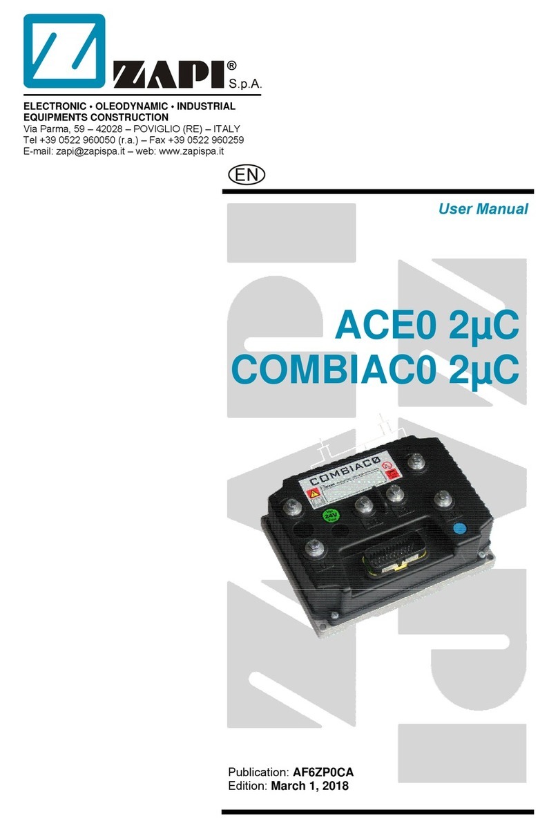
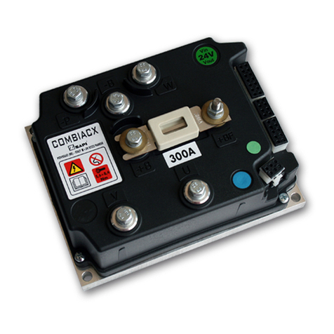
Zapi COMBI AC1 User manual

ELECTRONIC • OLEODYNAMIC • INDUSTRIAL
EQUIPMENTS CONSTRUCTION
Via Parma, 59 – 42028 – POVIGLIO (RE) – ITALY
Tel +39 0522 960050 (r.a.) – Fax +39 0522 960259
EN
User Manual
COMBI AC1

Copyright © 1975-2006 Zapi S.p.A.
All rights reserved
The contents of this publication is a ZAPI S.p.A. property; all related authorizations are covered
by Copyright. Any partial or total reproduction is prohibited.
Under no circumstances will Zapi S.p.A. be held responsible to third parties for damage caused
by the improper use of the present publication and of the device/devices described in it.
Zapi spa reserves the right to make changes or improvements to its products at any time and
without notice.
The present publication reflects the characteristics of the product described at the moment of
distribution. The publication therefore does not reflect any changes in the characteristics of the
product as a result of updating.
is a registered trademark property of Zapi S.p.A.
NOTES LEGEND
4The symbol aboard is used inside this publication to indicate an annotation or a
suggestion you should pay attention.
UThe symbol aboard is used inside this publication to indicate an action or acharacteristic very important as for security. Pay special attention to the
annotations pointed out with this symbol.
Page - 2/86 AEQZP0BA – COMBI AC1 - User Manual

Contents
1INTRODUCTION ...................................................................................................................6
2SPECIFICATION...................................................................................................................7
2.1 Technical specifications..............................................................................................7
2.2 Block diagrams ...........................................................................................................7
3SPECIFICATION FOR THE INPUT DEVICES FILLING UP THE INSTALLATION KIT.......8
3.1 Digital inputs ...............................................................................................................8
3.1.1 DIs technical details – 24 V system ..............................................................8
3.1.2 DIs technical details – 48 V system ..............................................................8
3.1.3 Microswitches ...............................................................................................8
3.2 Analog unit..................................................................................................................9
3.3 Other analog control unit ............................................................................................9
3.4 Analog motor thermal sensor input...........................................................................10
3.5 Speed feedback........................................................................................................10
4INSTALLATION HINTS.......................................................................................................11
4.1 Material overview......................................................................................................11
4.1.1 Connection cables ......................................................................................11
4.1.2 Contactors...................................................................................................11
4.1.3 Fuses ..........................................................................................................12
4.2 Installation of the hardware.......................................................................................12
4.2.1 Positioning and cooling of the controller .....................................................12
4.2.2 Wirings: power cables.................................................................................13
4.2.3 Wirings: CAN connections and possible interferences ...............................13
4.2.4 Wirings: I/O connections .............................................................................15
4.2.5 Connection of the encoder..........................................................................16
4.2.6 Main contactor and key connection ............................................................17
4.2.7 Insulation of truck frame..............................................................................18
4.3 Protection and safety features ..................................................................................19
4.3.1 Protection features......................................................................................19
4.3.2 Safety Features...........................................................................................20
4.4 EMC..........................................................................................................................20
4.5 Various suggestions .................................................................................................22
5OPERATIONAL FEATURES ..............................................................................................23
5.1 Diagnosis ..................................................................................................................23
6DESCRIPTION OF THE CONNECTORS............................................................................24
6.1 Connectors of the logic .............................................................................................24
6.1.1 CNA connector: AmpSaab Version.............................................................25
6.1.2 CNA connector: AmpSeal version ..............................................................26
6.2 Description of power connections.............................................................................28
7DRAWINGS.........................................................................................................................29
7.1 Mechanical drawing ..................................................................................................29
7.2 Connection drawing ..................................................................................................30
7.2.1 AmpSaab version........................................................................................30
7.2.2 AmpSeal version.........................................................................................31
8ONE SHOT INSTALLATION PROCEDURE.......................................................................32
8.1 Sequence for Ac Inverter traction setting..................................................................33
9PROGRAMMING & ADJUSTMENTS USING DIGITAL CONSOLE...................................35
9.1 Adjustments via console ...........................................................................................35
AEQZP0BA – COMBI AC1 - User Manual Page - 3/86

9.2 Description of console (hand set) & connection ....................................................... 35
9.3 Description of the console menu .............................................................................. 36
9.3.1 Master: AmpSaab version .......................................................................... 36
9.3.2 Master: AmpSeal version ........................................................................... 37
9.3.3 Slave: AmpSaab version ............................................................................ 38
9.3.4 Slave: AmpSeal version .............................................................................39
9.4 Function configuration (MASTER)............................................................................40
9.4.1 Config menu “SET OPTIONS” functions list...............................................40
9.4.2 Config menu “ADJUSTMENTS” functions list ............................................42
9.4.3 Main menu “PARAMETER CHANGE” functions list...................................44
9.4.4 Zapi menu “SPECIAL ADJUSTMENTS” functions list................................ 47
9.4.5 Main menu “TESTER” functions list ...........................................................48
9.5 Function configuration (SLAVE) ............................................................................... 51
9.5.1 Config menu “SET OPTIONS” functions list...............................................51
9.5.2 Config menu “ADJUSTMENTS” functions list ............................................51
9.5.3 Config menu “PARAMETER CHANGE” functions list ................................ 52
9.5.4 Config menu “SPECIAL ADJUSTMENTS ” functions list ...........................54
9.5.5 Config menu “TESTER ” functions list........................................................55
10 OTHER FUNCTIONS..........................................................................................................57
10.1 Description of console “SAVE” function ...................................................................57
10.2 Description of console “RESTORE” function............................................................58
10.3 Description of console “PROGRAM VACC” function................................................ 59
10.4 Description of the throttle regulation......................................................................... 61
10.5 Description of the battery charge detection setting .................................................. 62
11 COMBI AC1 ALARMS LIST ...............................................................................................64
11.1 Faults diagnostic system .......................................................................................... 64
11.2 Master microcontroller alarms overview ................................................................... 65
11.3 Analysis and troubleshooting of Master microcontroller alarms ............................... 66
11.4 Master warnings overview........................................................................................ 72
11.5 Analysis and troubleshooting of Master warnings ....................................................73
11.6 Slave alarms overview .............................................................................................76
11.7 Analysis and troubleshooting of Slave alarms..........................................................77
11.8 Slave warnings overview.......................................................................................... 80
11.9 Analysis and troubleshooting of Slave warnings ......................................................81
12 RECOMMENDED SPARE PARTS.....................................................................................85
13 PERIODIC MAINTENANCE TO BE REPEATED AT TIMES INDICATED.........................86
Page - 4/86 AEQZP0BA – COMBI AC1 - User Manual

APPROVAL SIGNS
COMPANY FUNCTION INIZIALS SIGN
GRAPHIC AND LAYOUT FF
PROJECT MANAGER FG
TECHNICAL ELECTRONIC
MANAGER VISA PP
SALES MANAGER VISA PN
Publication N°: AEQZP0BA
Edition: August 2005
AEQZP0BA – COMBI AC1 - User Manual Page - 5/86

1 INTRODUCTION
The COMBI AC1 inverter has been developed to perform all the electric functions
that are usually presents in walkie trucks, stackers, low order pickers etc.
The controller can perform the following functions:
- Controller for Ac 700W to 3.5Kw AC motors;
- Pump controller for series wounded DC motors up to 7,5 Kw.
- Drivers for ON/OFF electrovalves and for one proportional valve
(electrodistributor)
- Can bus interface
- Interface for serial tiller head, canbus tiller or serial tiller
- Zapi patented sensorless control
- Flash memory.
- Double microcontroller (one for main tasks, one for safety related tasks)
Page - 6/86 AEQZP0BA – COMBI AC1 - User Manual

2 SPECIFICATION
2.1 Technical specifications
Inverter for traction AC asynchronous 3-phase motors plus chopper for DC series
pump motors.
Regenerative braking functions.
Digital control based upon microcontroller
Voltage: ................................................................................................. 24, 36, 48V
Inverter maximum current (24V, 36V): ........................................ 350A (RMS) for 2'
Inverter maximum current (36V, 48V): ........................................ 300A (RMS) for 2'
Inverter operating frequency: ......................................................................... 8kHz
Dc chopper Maximum current (24V,36V):............................................. 350A for 2'
Dc chopper Maximum current (36V, 48V):............................................. 300A for 2’
Chopper Operating frequency:..................................................................... 16kHz
External temperature working range: ................................................. -40°C ÷ 40°C
Maximum heatsink temperature (start of the thermal cutback) ....................... 85°C
2.2 Block diagrams
AEQZP0BA – COMBI AC1 - User Manual Page - 7/86

3 SPECIFICATION FOR THE INPUT DEVICES
FILLING UP THE INSTALLATION KIT
3.1 Digital inputs
Combi Ac1 digital inputs work in the voltage range [-B; +B]. Related command
devices (microswitches) must be connected to +B (typically to key voltage).
Pull-down resistance to –B is built-in.
Functional devices (like FW, BACK, LIFT, DESCENT, HORN, H&S, TILLER,
BELLY switches) are Normally Open; so related function becomes active when
the microswitch closes.
Safety devices (like CUTBACK, LIFTING CUTOUT switches) are Normally
Closed; so related function becomes active when the microswitches opens.
A number of Dis are input to both microcontrollers, for safety purpose (double-
check in real time). They are listed here following:
- AMP SAAB version: A7, A5, A11, A18, A19, A20, A33, A34, A35, A6
- AMP SEAL version: A1, A20, A6, A32, A31, A19, A7, A35, A17, A29
It is recommended to connect SAFETY RELATED devices to these double-
checked inputs, in order to increase the application safety level.
3.1.1 DIs technical details – 24 V system
- Switching threshold: 3V [±0,5V]
- Input impedance: 4,7kOhm [±0,5kOhm]
3.1.2 DIs technical details – 48 V system
- Switching threshold: 3V [±0,5V]
- Input impedance: 13kOhm [±1kOhm]
3.1.3 Microswitches
- It is suggested that microswitches have a contact resistance lower than
0,1Ohm and a leakage current lower than 100µA.
- When full load connected, the voltage between the key switch contacts must
be lower than 0.1V.
- If the microswitch to be used has different characteristic, it is suggested to
discuss them and their application with Zapi technicians.
Page - 8/86 AEQZP0BA – COMBI AC1 - User Manual

3.2 Analog unit
The analog input can be connected to an accelerator unit if the Zapi can or serial
tiller is not used.
The accelerator unit can consist of a potentiometer or an Hall effect device.
It should be in a 3-wire configuration. The potentiometer is supplied through
CNA#26 [AmpSaab connector] OR CNA#25 [Ampseal connector].
Potentiometer output signal must be input to CPOT (CNA#24 for AmpSaab
connector, CNA#15 for Ampseal connector) signal range is from 0 to 10V.
The negative supply of the potentiometer has to be taken from CNA#23
[AmpSaab connector] OR CNA#5 [AmpSeal connector]
Potentiometer value should be in the 0.5 - 10 KΩrange; generally, the load
should be in the 1.5mA to 30mA range. Faults can occur if it is outside this range.
This AI is input to both microcontrollers, for safety purpose (double check in real
time).
The standard connection for the potentiometer is the one in the Left side of next
figure (potentiometer on one end at rest) in combination with a couple of Travel
demand switches (figure refers to AmpSaab connector). On request it is also
possible the handling in the Right side of next figure (potentiometer in the middle
at rest) still in combination with a couple of Travel demand switches.
The Procedure for automatic potentiometer signal acquisition is carried out using
the Hand Set. This enables adjustment of the minimum and maximum useful
signal level, in either direction.
3.3 Other analog control unit
If the Zapi can tiller is not used, input CNA#25 [AmpSaab connector] or CNA#30
[AmpSeal connector] is an analog input, whose typical application is a
proportional command to enable a lifting/lowering function. It is possible to use
this input for an alternative function like a proportional braking.
It should be in a 3 wire configuration. Potentiometer value should be in the 0.5-
10KΩrange. Generally, the load should be in the 1.5mA to 30 mA range.
The CPOTL [CNA#25 AmpSaab connector, CNA#30 AmpSeal connector] signal
range is from 0 to 10V.
Use CNA#26 [CNA#25] (positive) and CNA#41 [CNA#5] (negative) to supply it.
In the AmpSaab version the NPOT input [CNA#23] can be used as third analog
input. In this case use CAN#41 as negative supply of the traction potentiometer
(the “PEDAL WIRE KO” warning is lost).
AEQZP0BA – COMBI AC1 - User Manual Page - 9/86

Also in AmpSeal version a third analog input is available in CNA#17 (a digital
input is lost).
These other two analog inputs are checked by both microcontrollers too.
3.4 Analog motor thermal sensor input
Input CNA#12 in the AmpSaab version [CNA#22 in AmpSeal connector] is an
analog input to receive an analog thermal sensor signal to measure the Traction
Motor Winding Temperature. The analog device installed in the motor has to be
specified, in order to insert the correct look-up table in the software. A digital
device can also be used.
3.5 Speed feedback
The motor control is based upon the motor speed feedback (sensored software).
The speed transducer is an incremental encoder, with two phases shifted at 90°.
The encoder can be of different types :
- power supply: +12V
- electric output: open collector ( NPN or PNP), push-pull.
COMBI AC1 could also be used without encoder, sensorless control.
This solution has to be discussed with Zapi technicians.
4Note: The encoder resolution and the motor poles pair (the controller can
handle), is specified in the home page display of the handset showing following
headline:
CA1S2AE ZP1.07
That means:
CA1S= COMBIAC1 traction controller
2 = motor’s poles pair number
A = 32 pulses/rev encoder
E = identifier for an extended memory hardware release inside
The encoder resolution is given by the second-last letter in the following list:
A = 32 pulses/rev
K = 48 pulses/rev
B = 64 pulses/rev
C = 80 pulses/rev
Page - 10/86 AEQZP0BA – COMBI AC1 - User Manual

4 INSTALLATION HINTS
In the description of these installation suggestions you will find some boxes of
different colours, they mean:
4These are informations useful for anyone is working on the installation, or a
deeper examination of the content
UThese are Warning boxes, they describe:
- operations that can lead to a failure of the electronic device or can be
dangerous or harmful for the operator;
- items which are important to guarantee system performance and safety
4.1 Material overview
Before to start it is necessary to have the required material for a correct
installation. Otherwise a wrong choice of cables or other parts could lead to
cables to the battery should be run
is feature is useful to decrease
U
failures/ misbehaviour/ bad performances.
4.1.1 Connection cables
For the auxiliary circuits, use cables 0.5mm² section at least.
For power connections to the motor and to the battery, use cables having section
of 16-25 mm².
For the optimum inverter performance, the
and be as short as possible.side by side
4.1.2 Contactors
IT IS STRONGLY RECCOMENDED TO USE A MAIN CONTACOTOR to
connect and cut off the battery to the controller. Depending on the setting of a
parameter in the controller:
- the output which drives the main contactor coil is on/off (the coil is driven with
the full battery voltage).
- the output which drives the main contactor coil is switched at high frequency
(1 KHz) with a programmable duty cycle; th
the power dissipation of the contactor coil.
The EN1175 states the main Contactor is not mandatory (under proper
conditions); anyway it is recommended to protect the inverter against
reverse battery polarity and to cut off the battery from the power mosfets
when a failure in the three phase bridge occurs.
AEQZP0BA – COMBI AC1 - User Manual Page - 11/86

4.1.3 Fuses
- Use a 6.3-10A Fuse for protection of the auxiliary circuits.
- For protection of the power unit, use a 400A fuse in the Battery Positive
connection. For special applications or requirements these values can be
reduced.
- For Safety reasons, we recommend the use of protected fuses in order to
prevent the spread of fused particles should the fuse blow.
4.2 Installation of the hardware
UBefore doing any operation, ensure that the battery is disconnected andwhen all the installation is completed start the machine with the drive
wheels raised from the floor to ensure that any installation error do not
compromise safety.
After operation, even with the Key Switch open, the internal capacitors may
remain charged for some time. For safe operation, we recommend that the
battery is disconnected, and a short circuit is made between Battery
Positive and Battery Negative power terminals of the chopper using a
Resistor between 10 Ohm and 100 Ohm. Minimum 5 Watts.
4.2.1 Positioning and cooling of the controller
CONTROLLER WITH BASE PLATE: Install the controller with the base-plate on
a flat metallic surface that is clean and unpainted; suggested characteristics are:
planarity 0.05 mm and rugosity 1.6 µm
- Apply a light layer of thermo-conductive grease between the two surfaces to
permit better heat dissipation.
- The heat generated by the power block must be dissipated. For this to be
possible, the compartment must be ventilated and the heat sink materials
ample.
- The heat sink material and system should be sized on the performance
requirement of the machine. Abnormal ambient air temperatures should be
considered. In situations where either ventilation is poor, or heat exchange is
difficult, forced air ventilation should be used.
The thermal energy dissipated by the power block mo
dependent on the current drawn and the duty cycle.
- dule varies and is
CONTROLLER WITH FINNED HEATSINK: Sometimes the base plate
installation cannot be adopted. Due to positioning problems or to the lack of a
thick enough truck frame, it is necessary to adopt a finned dissipation combined
with one or more fans.
- The air flux should hit the fins directly, to maximize the cooling effect.
- In addition to fans, also air ducting systems can be used to maintain low the
temperature of the controller.
- It is necessary to ensure that cold air is taken from outside the controller
compartment and hot air is easily pushed away from the controller
compartment.
- It is mandatory to avoid that the cooling air is recirculated inside the controller
compartment.
Page - 12/86 AEQZP0BA – COMBI AC1 - User Manual

4.2.2 Wirings: power cables
- The power cables length must be as short as possible to minimize power
losses.
- They must be tightened on controller power posts with a Torque of 13-15 Nm
- The COMBI AC-1 module should only be connected to a traction battery. Do
not use converters outputs or power supplies. For special applications please
contact the nearest Zapi Service Centre.
UDo not connect the controller to a battery with a nominal voltage differentthan the value indicated on the controller label. A higher battery voltage
may cause MOS failure. A lower voltage may prevent the logic operating.
4.2.3 Wirings: CAN connections and possible interferences
4CAN Stands for Controller Area Network. It is a communication protocol for real
time control applications. CAN operates at data rate of up to 1 Megabits per
second.
It was invented by the German company Bosch to be used in the car industry to
permit communication among the various electronic modules of a vehicle,
connected as illustrated in this image:
- The best cable for can connections is the twisted pair; if it is necessary to
increase the immunity of the system to disturbances, a good choice would
be to use a cable with a shield connected to the frame of the truck.
Sometimes it is sufficient a simple double wire cable or a duplex cable not
shielded.
- In a system like an industrial truck, where power cables carry hundreds of
Ampere, there are voltage drops due to the impedance of the cables, and
that could cause errors on the data transmitted through the can wires. In the
following figures there is an overview of wrong and right layouts of the cables
routing.
AEQZP0BA – COMBI AC1 - User Manual Page - 13/86

UWrong Layout:
The red lines are can wires.
ample traction controller, pumpThe black boxes are different modules, for ex
nbus.controller and display connected by ca
he black lines are the power cables.T
This is apparently a good layout, but can bring to errors in the can line.
olution depends on the type of nodes (modules) connected in theThe best s
network.
t in terms of power, then the preferableIf the modules are very differen
connection is the daisy chain.
Module
1 Module
2
Module
3
UCorrect Layout:
Note: Module 1 power > Module 2 power > Module 3 power
The chain starts from the –BATT post of the controller that works with the
highest current, and the others are connected in a decreasing order of power.
Module
1 Module
2
Module
3
Page - 14/86 AEQZP0BA – COMBI AC1 - User Manual

Otherwise, if two controllers are similar in power (for example a traction and a
pump motor controller) and a third module works with less current, the best way
to deal this configuration is to create a common ground point (star configuration)
UCorrect Layout:
Note: Module 1 power ≈Module 2 power > Module 3 power
In this case the power cables starting from the two similar controllers must be as
short as possible. Of course also the diameter of the cable concurs in the voltage
drops described before (higher diameter means lower impedance), so in this last
example the cable between the minus of the Battery and the common ground
point (pointed by the arrow in the image) must dimensioned taking into account
thermal and voltage drop problems.
Module
1 Module
2
Module
3
4Can advantages
The complexity of today systems needs more and more data, signal and
information must flow from a node to another. CAN is the solution to different
problems that arise from this complexity
- simplified design (readily available, multi sourced components and tools)
- lower costs (less and smaller cables )
- improved reliability (fewer connections)
- analysis of problems improved (easy connection with a pc to read the data
flowing through the cable)
4.2.4 Wirings: I/O connections
- After crimping the cable, verify that all strands are entrapped in the wire
barrel.
- Verify that all the crimped contacts are completely inserted on the connector
cavities
UA cable connected to the wrong pin can lead to short circuits and failure;
so, before turning on the truck for the first time, verify with a multimeter the
continuity between the starting point and the end of a signal wire
- connector pin assignment see the paragraph
“description of the connectors”
for information about the mating
AEQZP0BA – COMBI AC1 - User Manual Page - 15/86

4.2.5 Connection of the encoder
1) COMBI AC1 card is fit for different types of encoder. To control AC motor
with Zapi inverter, it is necessary to install an incremental encoder with 2
phases shifted of 90°. The encoder power supply can be +5 or +12V. It can
have different electronic output.
AMPSAAB VERSION
A9 +5V/+12V positive of encoder power supply.
A10 GND negative of encoder power supply.
A8 A phase A of encoder.
A22 B phase B of encoder.
AMPSEAL VERSION
A25 +5V/+12V positive of encoder power supply.
A5 GND negative of encoder power supply.
A14 A phase A of encoder.
A13 B phase B of encoder.
2) Connection of encoder with open collector output; +5V power supply.
AMPSAAB VERSION
AMPSEAL VERSION
Connection of encoder with open collector output: +12V power supply.
AMPSAAB VERSION
Page - 16/86 AEQZP0BA – COMBI AC1 - User Manual

AMPSEAL VERSION
UVERY IMPORTANTIt is necessary to specify in the order the type of encoder used, in terms of
power supply, electronic output and n° of pulses for revolution, because
the logic unit must be set in the correct way by Zapi.
The n° of pulses revolution the controller can handle is given by the
second-last letter in the software release name (see 3.5).
4.2.6 Main contactor and key connection
- The connection of the main contactor can be carried out following the
drawing in the figure.
AMPSAAB VERSION
AMPSEAL VERSION
- The connection of the battery line switches must be carried out following
ZAPI instructions.
If a mechanical battery line switch is installed, it is strongly recommended
that the key supply to the inverter is open together with power battery line
(see picture below); if not, the inverter may be damaged if the switch is
-
opened during a regenerative braking.
- An intrinsic protection is present inside the logic when the voltage on the
battery power connection overtakes 40% more than the battery nominal
AEQZP0BA – COMBI AC1 - User Manual Page - 17/86

voltage or if the key is switched off before the battery power line is
disconnected.
AMPSAAB VERSION
AMPSEAL VERSION
4.2.7 Insulation of truck frame
UAs stated by EN-1175 “Safety of machinery – Industrial truck”, chapter 5.7,“there shall be no electrical connection to the truck frame”. So the truck
frame has to be isolated from any electrical potential of the truck power
line.
Page - 18/86 AEQZP0BA – COMBI AC1 - User Manual

4.3 Protection and safety features
4.3.1 Protection features
The COMBI AC1 is protected against some controller injuries and malfunctions:
- Battery polarity inversion
It is necessary to fit a LINE CONTACTOR to protect the controller against
reverse battery polarity and for safety reasons.
- Connection Errors
All inputs are protected against connection errors.
- Thermal protection
If the controller temperature exceeds 85°C, the maximum current is reduced in
proportion to the thermal increase. The temperature can never exceeds 105°C.
- External agents
The inverter is protected against dust and the spray of liquid to a degree of
protection meeting IP65. Nevertheless, it is suggested to carefully study
controller installation and position. With few simple shrewdness, the degree of
controller protection can be strongly increased.
- Protection against uncontrolled movements
The main contactor will not close if:
- The Power unit is not functioning.
- The Logic or CANBUS interface is not functioning perfectly.
- The Can Tiller is not operating correctly.
- Running microswitches are in open position.
- Low battery charge
when the battery charge is low, the maximum current is reduced to the half of the
maximum current programmed; additionally an alarm message is displayed.
- Protection against accidental Start up
A precise sequence of operations are necessary before the machine will start.
Operation cannot begin if these operations are not carried out correctly.
Requests for drive must be made after closing the key switch.
AEQZP0BA – COMBI AC1 - User Manual Page - 19/86

4.3.2 Safety Features
UZAPI controllers are designed according to the prEN954-1 specifications forsafety related parts of control system and to UNI EN1175-1 norm. The
safety of the machine is strongly related to installation; length, layout and
screening of electrical connections have to be carefully designed.
ZAPI is always available to cooperate with the customer in order to evaluate
installation and connection solutions. Furthermore, ZAPI is available to
develop new SW or HW solutions to improve the safety of the machine,
according to customer requirements.
Machine manufacturer holds the responsibility for the truck safety features
and related approval.
COMBI AC1 electronic implements a double µC structure. The second µC main
task is to check correct functionality of the first µC, whose main task is to control
traction AC motor. In more detail:
- first microcontroller manages Ac traction motor control and hydraulic safety
related functions.
second microcontroller manages Dc
traction safety related functions.
- pump motor control, valves control and
Basically, the two microcontrollers implement a double check control of the
main functions.
4.4 EMC
UEMC and ESD performances of an electronic system are strongly
influenced by the installation. Special attention must be given to the
lengths and the paths of the electric connections and the shields. Th
situation is beyond ZAPI's control. Zapi can offer assistance and
suggestions, based on its years experience, on EMC related items.
However, ZAPI declines any responsibility for non-compliance,
is
malfunctions and failures, if correct testing is not made. The machine
manufacturer holds the responsability to carry out machine validation,
based on existing norms (EN12895 for industrial truck; EN50081-2 for other
applications).
EMC stands for Electromagnetic Compatibility, and it represents the studies and
the tests on the electromagnetical energy
evice.
generated or received by an electrical
1)
d
So the analysis works in two directions:
The study of the emission problems, the disturbances generated by the
device and the possible countermeasure to prevent the propagation of that
energy; we talk about “conduction” issues when guiding structures such wires
and cables are involved, “radiated emissions” issues when it is studied the
propagation of electromagnetic energy through the open space. In our case
the origin of the disturbances can be found inside the controller with the
Page - 20/86 AEQZP0BA – COMBI AC1 - User Manual
Table of contents
Other Zapi Inverter manuals
Popular Inverter manuals by other brands

Craftsman
Craftsman 580.326300 owner's manual

Huawei
Huawei SUN2000-50KTL-JPM0 user manual

CPS
CPS SCA23 Installation and operation manual

SHENZHEN ENCOM ELECTRIC TECHNOLOGIES CO.
SHENZHEN ENCOM ELECTRIC TECHNOLOGIES CO. EDS1000 series Service manual

Hoymiles
Hoymiles HMS-2000D-4T Quick installation guide

Solectria Renewables
Solectria Renewables PVI 13KW Installation and operation manual