EN - 9
A number of important conditions must
be met to ensure the ventilation system
functions properly:
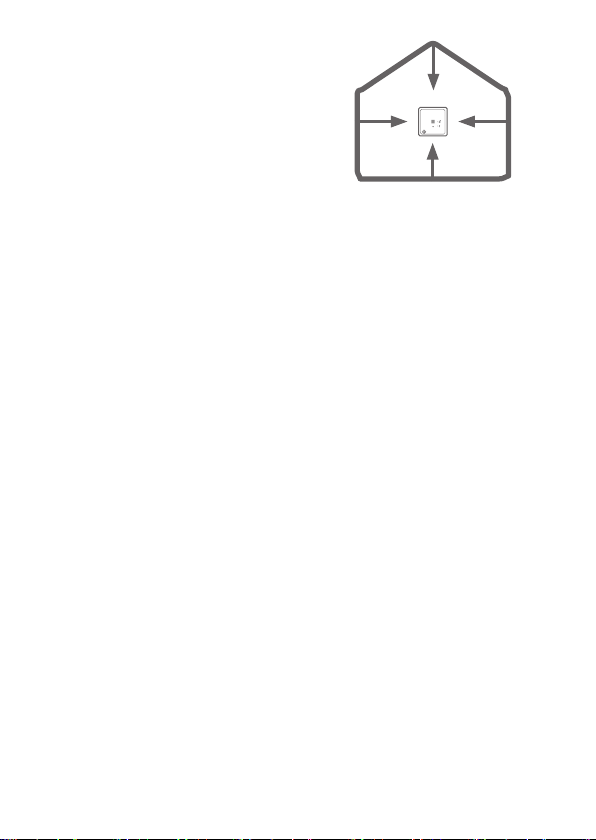
■Do not place objects such as for
example cabinets in front of the control
unit.
■Ensure a sufficient supply of air. For
example, open a small window or any
trickle vent in a window, window frame
or sliding door.
■If the home is fitted with non-lockable
air openings, such as trickle vents above
the windows or gaps under doors, then
leave these open. Do not cover or block
them.
■Ensure that there is no powered
extractor hood connected to the
ventilation system.
4.1 Setting ventilation level
A manual ventilation mode cannot be set on
all control units. This is only possible on a
control unit set by the installer as the main
control unit or as a CO2controller.
In manual ventilation mode,
ventilation is not controlled on the
basis of the CO2levels.
A manual ventilation mode
remains active for up to 12 hours.
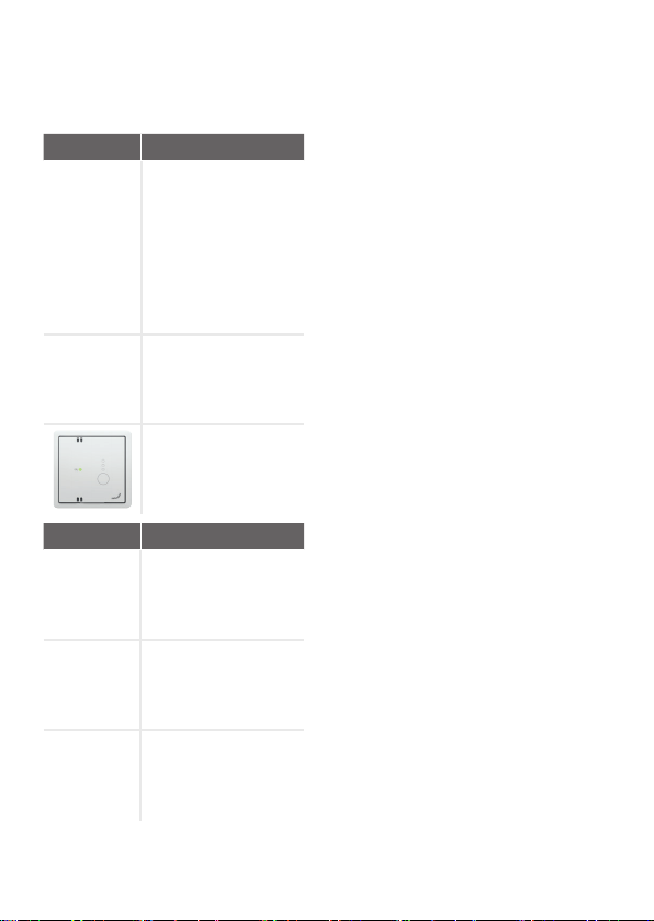
1. If indicators are on full: Press the
operating button briefly.
- The indicators will fully light up.
2. Briefly press the operating button to
select a different ventilation level.
3. Repeat step 2 until the indicators of the
desired ventilation level light up.
If only the CO2indicator is lit, the control unit
is set to automatic ventilation.
4.2 Setting brightness
The brightness of the indicators can be set
to the following levels:
bright, high, medium, low, warning, off.
The default setting is: warning - the CO2
indicator only shows increased CO2level or
malfunction alerts.
1. Press the operating button for 5
seconds.
- All the indicators flash green 3x.
- The bottom (RF) or middle (0-10 V)
indicator in the right column flashes
red.
2. Briefly press the operating button within
30 seconds.
- The top indicator in the right column
flashes red.
3. Press the operating button for 5
seconds.
- All the indicators flash green 3x.
4. Briefly press the operating button to
select a different brightness level.
5. Repeat step 4 until the indicators of the
desired brightness light up.
6. Press the operating button for 5
seconds.
- All the indicators flash green 3x.
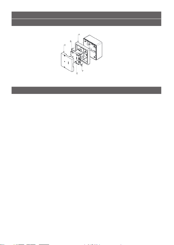
5 Installation
The letters in this chapter refer to the
illustrations at the beginning of this
document.
1. If wall-mounted model:
Fasten the housing for wall mounting
in the living area at a user-accessible
location on the wall:
■ At least 1 metre above the floor;
■ At most 1.5 metres above the floor.
2. Fasten wall frame A with screws F (not
included) to the wall, the housing for
wall mounting or the installation plate.
3. Route the cables through the desired
design frame X and adjust the size of
window D, where relevant.
4. Connect the cables to the control unit
and ventilation system.
■ Consult the relevant manual for
details of connection to the ventilation
unit.
5. Fasten the unit B with design frame X
and format adaptation window D, where
relevant, to frame A with screws E.
6. Push cap C into place.