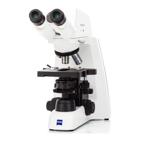
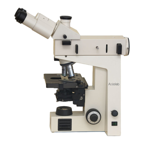
Zeiss Axio Scope.A1 User manual

Operating Manual
Axio Scope.A1
Microscope for Routine and Entry-Level Research

Carl Zeiss Copyright / Trademark Axio Scope.A1
2 M60-2-0007 e 05/08
A thorough knowledge of these instructions is mandatory in order to operate the machine. Please
familiarize yourself with the content and follow the safety instructions by all means.
We reserve the right to make changes in the interest of further technical development. The manual is not
subject to updating.
© Passing on and reproduction of this document, utilization and notice of its content are not
permitted unless explicitly allowed. Noncompliance is bound to indemnity.
All rights reserved, including rights created by patent grant or registration of a utility model or design.
Brands and names indicated in this manual may be trademarks of other companies. These brands and
names are mentioned only for information and do not express any approval or recommendation by us.
Carl Zeiss MicroImaging GmbH cannot assume any liability for the performance or the use of these
brands.
Published by: Carl Zeiss MicroImaging GmbH
PO Box 4041, D - 37030 Goettingen
Telephone: +49 551 5060 660
Telefax: +49 551 5060 464
www.zeiss.de
Number of the manual: M60-2-0007 e
Issue date: Version 6 – 13-05-2008

Axio Scope.A1 Content / Figures Carl Zeiss
M60-2-0007 e 05/08 3
CONTENT
Page
1INTRODUCTION ...................................................................................................99
1.1 Safety Guidelines............................................................................................................ 99
1.2 Warranty........................................................................................................................914
1.3 Stand Variants............................................................................................................... 915
1.4 Interface Diagram ......................................................................................................... 117
1.5 Summary of the Controls and Functional Elements................................................... 119
2TECHNICAL MANUAL ........................................................................................121
2.1 Intended Use ................................................................................................................. 121
2.2 Systems Overview ........................................................................................................ 122
2.3 Technical Data............................................................................................................... 127
3STARTUP ............................................................................................................129
3.1 Mounting the Standard Components ......................................................................... 129
3.1.1 Unpacking and Mounting the Microscope Stand.............................................................. 129
3.1.2 Mounting the Upper Stand Part on the Stand Column ..................................................... 130
3.1.3 Mounting the Binocular Tube / Photo Tube...................................................................... 131
3.1.4 Inserting Eyepieces or an Auxiliary Microscope ................................................................. 131
3.1.5 Mounting Objectives........................................................................................................ 133
3.1.6 Installing and Uninstalling "Push&Click" Modules in the Reflector Insert .......................... 134
3.1.7 Mounting the Reflector Insert .......................................................................................... 135
3.1.8 Mounting the Mechanical Stage ...................................................................................... 136
3.1.9 Mechanical Stages with Friction Adjustment .................................................................... 139
3.1.10 Mounting the LED Illuminator for Transmitted Light......................................................... 141
3.1.11 Mounting the Condenser Carrier ..................................................................................... 142
3.1.12 Mounting the Condenser................................................................................................. 143
3.1.13 Mounting the Stage Carrier ............................................................................................. 144
3.1.14 Inserting the Halogen Lamp 12 V, 50 W........................................................................... 145
3.1.15 Halogen Lamp HAL 100................................................................................................... 146
3.1.16 Inserting the Adjustment Aid into the Upper Stand Part FL/HBO ....................................... 149
3.1.17 HBO 50 Illuminator .......................................................................................................... 149
3.1.18 HBO 100 Illuminator ........................................................................................................ 152
3.1.19 Illumination System Colibri and External Illumination Fixture HXP 120 .............................. 153
3.2 Connection of the Power Supply................................................................................. 154
3.2.1 Lower Stand Part for LED and HAL 50 Illumination............................................................. 154
3.2.2 Lower Stand Part for HAL 100 Illumination....................................................................... 154
3.2.3 Upper Stand Part for HAL 100/HBO, FL/HBO, FL-LED ........................................................ 155

Carl Zeiss Content / Figures Axio Scope.A1
4 M60-2-0007 e 05/08
3.3 Switching the Microscope and its Separate Illumination Fixtures on and off......... 155
3.4 Mounting Optional Components ................................................................................ 156
3.4.1 Changing the Upper Stand Part and Inserting a Centerpiece for Larger Specimens........... 156
3.4.2 Mounting the Intermediate Plate for Analyzer Slider......................................................... 157
3.4.3 Mounting the Tube Lens Turret........................................................................................ 157
3.4.4 Mounting the Magnification Changer.............................................................................. 158
3.4.5 Changing the Filters in the Reflector Module FL P&C........................................................ 158
3.4.6 Changing the Color Splitter in the Reflector Module FL P&C ............................................ 160
3.4.7 Mounting the Polarizer D or the Filter Holder ................................................................... 161
3.4.8 Mounting and Centering the Overview Fixture................................................................. 162
3.4.9 Changing the LED Module in the Upper Stand Part FL-LED............................................... 163
3.4.10 Inserting a Modulator Disk in the Condenser 0.9/1.25 H .................................................. 164
3.4.11 Changing the Diaphragm PlasDIC .................................................................................... 165
3.4.12 Changing the Diaphragm Ph-DIC on the Achromatic-Aplanatic Condenser
0.9 H D Ph DIC ................................................................................................................ 165
3.4.13 Changing the Filter in the Filter Wheel Transmitted Light ................................................. 166
3.5 Default Setting of the Microscope .............................................................................. 167
3.5.1 Adjusting the Eyepiece Distance (Distance of the Pupils) on the Binocular Tube .................. 167
3.5.2 Adjusting the Viewing Height .......................................................................................... 167
3.5.3 Correction of Vision Defects with the Eyepiece Graticules ................................................ 168
4OPERATION ....................................................................................................... 169
4.1 Illumination and Contrasting Method ........................................................................ 169
4.1.1 Adjusting the Transmitted Light/Bright-Field According to KÖHLER .................................. 169
4.1.2 Adjusting the Transmitted Light/Dark-Field According to KÖHLER .................................... 172
4.1.3 Adjusting the Transmitted Light/Phase-Contrast............................................................... 174
4.1.4 Adjusting the Transmitted Light/Differential Interference Contrast (DIC)........................... 176
4.1.5 Adjusting PlasDIC-Contrast in Transmitted Light .............................................................. 178
4.1.6 Adjusting Transmitted Light/Polarization .......................................................................... 179
4.1.7 Adjusting the Reflected Light/Bright-Field According to KÖHLER ...................................... 183
4.1.8 Adjusting the Reflected Light/Dark-Field........................................................................... 186
4.1.9 Adjusting Reflected Light DIC and Reflected Light C-DIC.................................................. 187
4.1.10 Adjusting Reflected Light TIC ........................................................................................... 188
4.1.11 Adjusting Reflected Light Polarization – Proof of Bireflexion and Reflexion pleochroism.... 191
4.1.12 Adjusting Reflected Light Fluorescence ............................................................................ 193
4.2 Operating and Functional Elements of Optional Components ................................. 195
4.2.1 Lower Stand Part for LED Transmitted Light Illumination .................................................. 195
4.2.2 Lower Stand Part with HAL 50 Illumination ...................................................................... 196
4.2.3 Lower Stand Part for HAL 100 Illumination ...................................................................... 197
4.2.4 Stand Column Vario 380 mm or 560 mm with Gear Box ................................................. 198
4.2.5 Upper Stand Part Transmitted Light ................................................................................. 199
4.2.6 Upper Stand Part FL/HBO ................................................................................................. 199
4.2.7 Upper Stand Part FL-LED ................................................................................................ 1100
4.2.8 Upper Stand Part HAL 100/HBO..................................................................................... 1101

Axio Scope.A1 Content / Figures Carl Zeiss
M60-2-0007 e 05/08 5
4.2.9 Upper Stand Part HAL 100/HBO DIC .............................................................................. 1101
4.2.10 Sideport ISCP T60N Left................................................................................................. 1102
4.2.11 Reflector Slider 2-fold .................................................................................................... 1103
4.2.12 Reflector Turret 4-fold or 6-fold ..................................................................................... 1103
5MAINTENANCE, CHANGING OF FUSES AND SERVICE ...................................1109
5.1 Maintenance................................................................................................................ 1109
5.2 Technical Service......................................................................................................... 1110
5.2.1 Check-Up ...................................................................................................................... 1110
5.2.2 Changing the Fuses ....................................................................................................... 1110
5.3 Trouble Shooting ........................................................................................................ 1111
5.4 Service.......................................................................................................................... 1114
6ANNEX .............................................................................................................1115
6.1 List of Abbreviations .................................................................................................. 1115
6.2 Subject Index............................................................................................................... 1117
6.3 Property Rights ........................................................................................................... 1121

Carl Zeiss Content / Figures Axio Scope.A1
6 M60-2-0007 e 05/08
FIGURES
0Fig. 1-1 Caution sign on lower stand part for HAL 100- and HAL 50-illumination.............................188H188H13
1H1HFig. 1-2 Caution sign on upper stand part FL-LED.............................................................................189H189H13
2H2HFig. 1-3 Interface diagram (upper stand part FL/HBO and lower stand part with
HAL 50 illumination) ...........................................................................................................190H190H18
3H3HFig. 1-4 Summary of the controls and functional elements ...............................................................191H191H20
4H4HFig. 3-1 Setting up the microscope...................................................................................................192H192H29
5H5HFig. 3-2 Mounting the upper stand part on the stand column ..........................................................193H193H30
6H6HFig. 3-3 Mounting the binocular tube ..............................................................................................194H194H31
7H7HFig. 3-4 Inserting eyepieces..............................................................................................................195H195H31
8H8HFig. 3-5 Inserting an eyepiece graticule ............................................................................................196H196H32
9H9HFig. 3-6 Mounting objectives............................................................................................................197H197H33
10H10HFig. 3-7 Changing the reflector module in the reflector insert ..........................................................198H198H34
11H11HFig. 3-8 Changing the reflector module in the upper stand part FL-LED............................................199H199H34
12H12HFig. 3-9 Mounting the reflector insert ..............................................................................................200H200H35
13H13HFig. 3-10 Changing the stable mechanical stage ................................................................................201H201H36
14H14HFig. 3-11 Changing the rotatable mechanical stage............................................................................202H202H36
15H15HFig. 3-12 Centering the rotatable mechanical stage ...........................................................................203H203H37
16H16HFig. 3-13 Adjusting ergonometric drive ..............................................................................................204H204H38
17H17HFig. 3-14 Adjusting the frictional momentum.....................................................................................205H205H39
18H18HFig. 3-15 Adjusting the connecting rod position for the ergo drive.....................................................206H206H40
19H19HFig. 3-16 Mounting the LED illuminator on the condenser..................................................................207H207H41
20H20HFig. 3-17 Connecting the LED illuminator...........................................................................................208H208H41
21H21HFig. 3-18 Mounting the condenser carrier ..........................................................................................209H209H42
22H22HFig. 3-19 Mounting the condenser.....................................................................................................210H210H43
23H23HFig. 3-20 Mounting the stage carrier..................................................................................................211H211H44
24H24HFig. 3-21 Removing a halogen lamp HAL 50 ......................................................................................212H212H45
25H25HFig. 3-22 Inserting a halogen lamp 12 V, 50 W ..................................................................................213H213H45
26H26HFig. 3-23 Mounting the halogen lamp HAL 100 .................................................................................214H214H46
27H27HFig. 3-24 Adjusting a halogen lamp HAL 100.....................................................................................215H215H47
28H28HFig. 3-25 Changing a halogen lamp...................................................................................................216H216H48
29H29HFig. 3-26 Inserting the adjustment aid................................................................................................217H217H49
30H30HFig. 3-27 Opening the HBO 50...........................................................................................................218H218H49
31H31HFig. 3-28 Changing the burner...........................................................................................................219H219H50
32H32HFig. 3-29 Mounting the HBO 50.........................................................................................................220H220H51
33H33HFig. 3-30 Adjusting the HBO 50 .........................................................................................................221H221H51
34H34HFig. 3-31 Mounting the HBO 100.......................................................................................................222H222H52
35H35HFig. 3-32 Transformer HBO 100 W.....................................................................................................223H223H52
36H36HFig. 3-33 Adjustment aid ...................................................................................................................224H224H53
37H37HFig. 3-34 Adjusting the HBO 100 .......................................................................................................225H225H53
38H38HFig. 3-35 Lower stand part for HAL 50 illumination (proceed analogically for LED illumination)...........226H226H54
39H39HFig. 3-36 Lower stand part for HAL 100 illumination ..........................................................................227H227H54
40H40HFig. 3-37 Auxiliary power supply unit HAL 100 (front and back) .........................................................228H228H55
41H41HFig. 3-38 Transformer HBO 100 W (front and back) ..........................................................................229H229H55
42H42HFig. 3-39 Changing the upper stand part, inserting a centerpiece.......................................................230H230H56
43H43HFig. 3-40 Mounting the binocular tube ..............................................................................................231H231H57

Axio Scope.A1 Content / Figures Carl Zeiss
M60-2-0007 e 05/08 7
44H44HFig. 3-41 Mounting the magnification changer ..................................................................................232H232H58
45H45HFig. 3-42 Changing the filters in the reflector module FL P&C.............................................................233H233H58
46H46HFig. 3-43 Mounting the filters and the color splitter ...........................................................................234H234H59
47H47HFig. 3-44 Opening the module ...........................................................................................................235H235H60
48H48HFig. 3-45 Changing the color filter .....................................................................................................236H236H60
49H49HFig. 3-46 Labeling the color splitter ....................................................................................................237H237H61
50H50HFig. 3-47 Mounting the polarizer D ....................................................................................................238H238H61
51H51HFig. 3-48 Mounting the overview fixture ............................................................................................239H239H62
52H52HFig. 3-49 Changing the LED module ..................................................................................................240H240H63
53H53HFig. 3-50 Modulator disk in condenser 0.9/1.25 H..............................................................................241H241H64
54H54HFig. 3-51 Mounting the slit-diaphragm...............................................................................................242H242H65
55H55HFig. 3-52 Changing the diaphragm Ph-DIC.........................................................................................243H243H65
56H56HFig. 3-53 Changing the filter in the filter wheel transmitted light........................................................244H244H66
57H57HFig. 3-54 Adjusting the eyepiece distance on the binocular tube ........................................................245H245H67
58H58HFig. 3-55 Adjusting the viewing height on the binocular tube ............................................................246H246H67
59H59HFig. 4-1 Microscope adjustment in transmitted light/bright-field.......................................................247H247H70
60H60HFig. 4-2 Adjusting the vertical stop on the condenser carrier.............................................................248H248H71
61H61HFig. 4-3 Adjusting the vertical stop on the focusing drive..................................................................249H249H71
62H62HFig. 4-4 Centering the dark-field diaphragm on the condenser,
achromatic-aplanatic 0.9 H D Ph DIC...................................................................................250H250H73
63H63HFig. 4-5 Centering the annular phase diaphragm (light-colored, in the condenser) and the
phase ring (dark-colored, in the object) ...............................................................................251H251H75
64H64HFig. 4-6 Components for the transmitted light/DIC method..............................................................252H252H77
65H65HFig. 4-7 Components for transmitted light polarization ....................................................................253H253H79
66H66HFig. 4-8 Determination of the polarization direction nγ'in a synthetic fiber .......................................254H254H80
67H67HFig. 4-9 Diagram of the color tables according to Michel-Lévy..........................................................255H255H81
68H68HFig. 4-10 External auxiliary power supply unit for HAL 100.................................................................256H256H83
69H69HFig. 4-11 Adjusting the microscope in the reflected light/bright-field..................................................257H257H85
70H70HFig. 4-12 Compensator compartment 6x20 with C-DIC slider 6x20 ....................................................258H258H87
71H71HFig. 4-13 TIC slider 6x20 ....................................................................................................................259H259H88
72H72HFig. 4-14 Interference stripes..............................................................................................................260H260H89
73H73HFig. 4-15 Components for reflected light polarization ........................................................................261H261H92
74H74HFig. 4-16 Components for reflected light fluorescence .......................................................................262H262H94
75H75HFig. 4-17 Lower stand part for LED transmitted light illumination .......................................................263H263H95
76H76HFig. 4-18 Lower stand part with HAL 50 illumination..........................................................................264H264H96
77H77HFig. 4-19 Lower stand part for HAL 100 illumination ..........................................................................265H265H97
78H78HFig. 4-20 Stand column Vario.............................................................................................................266H266H98
79H79HFig. 4-21 Upper stand part transmitted light ......................................................................................267H267H99
80H80HFig. 4-22 Upper stand part FL/HBO.....................................................................................................268H268H99
81H81HFig. 4-23 Upper stand part FL-LED....................................................................................................269H269H100
82H82HFig. 4-24 Upper stand part HAL 100/HBO ........................................................................................270H270H101
83H83HFig. 4-25 Upper stand part HAL 100/HBO DIC..................................................................................271H271H101
84H84HFig. 4-26 Sideport ISCP T60N left .....................................................................................................272H272H102
85H85HFig. 4-27 Reflector slider 2-fold ........................................................................................................273H273H103
86H86HFig. 4-28 Reflector turret 6-fold .......................................................................................................274H274H103
87H87HFig. 4-29 Condenser 0.9/1.25 H with modulator disk .......................................................................275H275H104
88H88HFig. 4-30 Nosepiece with compartment for compensators................................................................276H276H104
89H89HFig. 4-31 Binocular ergo tube...........................................................................................................277H277H105

Carl Zeiss Content / Figures Axio Scope.A1
8 M60-2-0007 e 05/08
90H90HFig. 4-32 Binocular photo tube ........................................................................................................278H278H106
91H91HFig. 4-33 Adjusting the viewing height on the binocular tube ..........................................................279H279H106
92H92HFig. 4-34 Mechanical stage with object holder .................................................................................280H280H107
93H93HFig. 4-35 Overview fixture................................................................................................................281H281H107
94H94HFig. 4-36 Diaphragm slider 14x40 mm .............................................................................................282H282H108
95H95HFig. 5-1 Changing the fuses on the stand.......................................................................................283H283H110

INTRODUCTION
Axio Scope.A1 Safety Guidelines Carl Zeiss
M60-2-0007 e 05/08 9
1INTRODUCTION
1.1 Safety Guidelines
The microscopes Axio Scope.A1 were engineered, manufactured and tested according to DIN EN 61010-1
(IEC 61010-1) and IEC 61010-2-101, safety regulations for metering, control and laboratory equipment.
The microscopes fulfill the requirements as stated in regulation 98/79/EG (In-Vitro-Diagnostika) and carry
the label .
The present manual gives information and safety warnings which must be followed by the operator.
The following warning and instruction icons are used in the manual:
CAUTION
Warns the operator of a possible danger.
CAUTION
Hot surface!
CAUTION
UV radiation!
BE CAREFUL, LED radiation!
LED class 3B, max. 30 mW, 365 - 625 nm,
Avoid direct exposure to the beam. Avoid contact with the skin!
CAUTION
Pull the plug before handling the instrument!
CAUTION
Possible danger for the instrument or the system.
ATTENTION
Points out instructions which should be followed carefully.

INTRODUCTION
Carl Zeiss Safety Guidelines Axio Scope.A1
10 M60-2-0007 e 05/08
The microscope Axio Scope.A1 and its genuine accessories may only be used for microscopy methods as
indicated in this manual.
The following guidelines are especially important:
The manufacturer admits no liability if the microscope, its components or single parts, are used
in any different manner. Liability is also excluded for any service or repair work performed by
non-authorized personnel and any rights to claims under guarantee expire.
The microscope may only be plugged into an electrical outlet equipped with a safety contact.
The safety aspect must not be disabled by using an extension cord which does not have a
ground wire.
Whenever it becomes apparent that any of the safety mechanisms is out of order, the
microscope must be switched off and protected from any accidental use. Please contact the
Zeiss Service Department or the Carl Zeiss Microscopy Service before switching the microscope
on again.
The lower stand parts for LED illumination and those with integrated HAL 50 illumination are
equipped with a power supply unit integrated in the stand. This unit adapts to a voltage range
of 100 to 240 V ±10 %, 50 / 60 Hz, no further voltage adjustment is necessary on the
microscope itself.
The auxiliary power supply unit SNT 12 V DC 100 W for HAL 100 covers a voltage range from
100 to 240 V AC ±10 %, 50 to 60 Hz. It adapts automatically to the applied voltage.
The transformers for the HBO 100 adapt to a voltage range from 100 to 240 V AC, 50 to
60 Hz. They adapt automatically to the applied voltage. No further voltage adjustment is
necessary.
However, the transformer for the HBO 50 must be adjusted according to the applied voltage
(100, 110, 120, 127 or 230, 240 V). Please do not forget to adjust the power frequency
accordingly (50 or 60 Hz).
Before you switch on the microscope, please verify that the voltage you are about to use is
suitable.
Always pull the plug before you open the microscope or change a fuse!
Please make sure that the fuses are suitable for the applied nominal current. Never use any
makeshift fuses and do not short-circuit the fuse holders.
The microscopes Axio Scope.A1 do not have any special safety fixtures to protect from acid,
potentially infectious, toxic, radioactive or other specimens potentially hazardous to your health.
All legal requirements, especially the national regulations for the prevention of accidents must
be followed.

INTRODUCTION
Axio Scope.A1 Safety Guidelines Carl Zeiss
M60-2-0007 e 05/08 11
Gas discharge lamps, e.g. HBO 100, emit ultraviolet radiation which may cause eye and skin
burns. Never look directly into the beam and avoid any direct skin exposure to the beam. Never
operate the microscope without the necessary safety equipment (e.g. special damping filters or
the fluorescence protection screen). Gas discharge lamps have a high internal pressure when
hot. Never change the lamps while they are still hot and make sure to always use protective
gloves and masks when changing them.
Microscope lamps radiate a lot of heat which could damage the heat sensitive fluorescence
filters. It is therefore necessary not to remove the heat protection filter when using a
fluorescence filter so that it can function properly.
Avoid any contact with the hot lamp case. Before you change a lamp, make sure to pull the
plug and wait 15 minutes for the lamp to cool down.
Dirt and dust may affect the microscope’s performance. Protect it by using a dust cover when it
is not in use. Always make sure that the instrument is switched off before covering it up.
Covering the ventilation slits may accumulate heat which could damage the instrument and
even start a fire. Make sure to keep the ventilation slits open and never put or accidentally drop
anything into them.
Only authorized personnel should be allowed to operate the instruments. The personnel must
be aware of the possible danger which might occur while using the microscope. The
Axio Scope.A1 is a precision tool which can easily be damaged or even destroyed when
handled improperly.
Never operate the instrument in an area with potentially explosive atmosphere.
Always place it on a stable and heat resistant surface.
Specimens must be disposed of appropriately according to valid legal regulations and internal
work instructions.
When the lamp module (e.g. Colibri) is equipped with appropriate LED modules, or when a
white light source coupled by a fluid light conductor is used, ultraviolet radiation may leak
which can cause eye and skin burns. Never look directly into the light and avoid any direct skin
exposure to the light. Always use the appropriate safety equipment when operating the
microscope.

INTRODUCTION
Carl Zeiss Safety Guidelines Axio Scope.A1
12 M60-2-0007 e 05/08
Never look into the light beam of the illumination equipment - with or without optical
instruments. Not even if you just want to look at a specimen. Irreparable eye damage may
occur!
Do not hold any flammable or easily combustible materials around the light beam.
Please read the safety data sheet on Immersol 518 N®, Immersol 518 F®and Immersol W®
carefully.
The immersion fluid Immersol 518 N®is irritant to the skin. Avoid any contact with skin, eyes
and clothes.
If skin contact occurs, wash off with lots of water and soap.
If eye contact occurs, flush with water immediately for at least 5 minutes. Seek medical
assistance if irritation continues.
Dispose of immersion fluid Immersol 518 N®appropriately: Do not allow to contaminate
surface water or get into drains.
Defective microscopes do not belong in the household garbage. Follow the appropriate legal
regulations for their disposal.
Specimens must also be disposed off appropriately according to valid legal regulations and
internal work instructions.

INTRODUCTION
Axio Scope.A1 Safety Guidelines Carl Zeiss
M60-2-0007 e 05/08 13
Caution signs on lower stand part for HAL 100- and HAL 50-illumination and on upper stand
part FL-LED
Fig. 1-1 Caution sign on lower stand part for HAL 100- and HAL 50-illumination
Fig. 1-2 Caution sign on upper stand part FL-LED

INTRODUCTION
Carl Zeiss Warranty Axio Scope.A1
14 M60-2-0007 e 05/08
1.2 Warranty
The manufacturer guarantees that the instrument is free of any material and workmanship defects upon
delivery. If you become aware of any deficiencies, please contact us immediately and take all necessary
precautions in order to avoid further damage. Upon notice of deficiencies it is up to the manufacturer’s
discretion to correct the deficiencies or to deliver a defect-free instrument. Defects due to ordinary wear
and tear (especially on wearing parts) and to improper handling are not covered by our warranty.
The manufacturer is not responsible for damages to the instrument which occur by maloperation,
negligence or any other manipulation of the instrument, especially if the damages occur while removing
or changing any parts or when using accessories from other manufacturers. This will immediately void the
warranty.
No maintenance or repair work, except for the instances mentioned in the manual, may be performed on
the microscopes. Only Carl Zeiss service personnel or personnel authorized especially by Carl Zeiss may
perform repair work on the microscopes. If your instrument happens to malfunction please contact the
Carl Zeiss Microscopy Service Department, Germany, (see p. 114) or the Carl Zeiss agency assigned to
your country.

INTRODUCTION
Axio Scope.A1 Stand Variants Carl Zeiss
M60-2-0007 e 05/08 15
1.3 Stand Variants
The shipment includes five different upper stand parts, three lower stand parts and two stand columns
which can be combined according to the following chart.
Upper stand
part
Lower stand
part
Upper stand part
Backlight
with nosepiece
6x bright field,
M27
Upper stand part
FL/HBO
with nosepiece
3x bright field, 3x
DIC, M27
Upper stand part
FL-LED
with nosepiece
3x bright field, 3x
DIC, M27
Upper stand part
HAL 100/HBO
with nosepiece 6x
bright/dark field,
M 27
Upper stand part
HAL 100/HBO
with nosepiece 6x
bright/dark field,
DIC, M27
Lower stand part
for LED
illumination
Microscope stand
"Axio Scope.A1"
LED,
6x H
430035-9200-000
Microscope stand
"Axio Scope.A1"
LED, FL/HBO,
3x H, 3x DIC
430035-9210-000
Microscope stand
"Axio Scope.A1"
LED, FL-LED,
3x H, 3x DIC
430035-9220-000
Microscope stand
"Axio Scope.A1"
LED,
HAL 100/HBO,
6x HD
430035-9080-000
Microscope stand
"Axio Scope.A1"
LED,
HAL 100/HBO,
6x HD DIC
430035-9090-000
Lower stand part
for HAL 50
illumination
Microscope stand
"Axio Scope.A1"
HAL 50,
6x H
430035-9030-000
Microscope stand
"Axio Scope.A1"
HAL 50,
FL/ HBO,
3x H, 3x DIC
430035-9040-000
Microscope stand
"Axio Scope.A1"
HAL 50, FL-LED,
3x H, 3x DIC
430035-9050-000
Microscope stand
"Axio Scope.A1"
HAL 50,
HAL 100/HBO,
6x HD
430035-9100-000
Microscope stand
"Axio Scope.A1"
HAL 50,
HAL 100/HBO,
6x HD DIC
430035-9110-000
Lower stand part
for HAL 100
illumination
Microscope stand
"Axio Scope.A1"
HAL 100, 6x H
430035-9130-000
Microscope stand
"Axio Scope.A1"
HAL 100, FL/HBO,
3x H, 3x DIC
430035-9060-000
Microscope stand
"Axio Scope.A1"
HAL 100, FL-LED,
3x H, 3x DIC
430035-9070-000
Microscope stand
"Axio Scope.A1"
HAL 100,
HAL 100/HBO,
6x HD
430035-9140-000
Microscope stand
"Axio Scope.A1"
HAL100,
HAL 100/HBO,
6x HD DIC
430035-9120-000

INTRODUCTION
Carl Zeiss Stand Variants Axio Scope.A1
16 M60-2-0007 e 05/08
Upper stand
part
Lower stand
part
Upper stand part
Backlight
with nosepiece
6x bright field,
M27
Upper stand part
FL/HBO
with nosepiece
3x bright field, 3x
DIC, M27
Upper stand part
FL-LED
with nosepiece
3x bright field, 3x
DIC, M27
Upper stand part
HAL 100/HBO
with nosepiece 6x
bright/dark field,
M 27
Upper stand part
HAL 100/HBO
with nosepiece 6x
bright/dark field,
DIC, M27
Stand column
"Axio Scope"
Vario 380 mm
Upper stand part
"Axio Scope"
FL/HBO,
3x H, 3x DIC, M27
423730-9030-000
Stand column
"Axio Scope"
Vario 380 mm
451017-9010-00
Focusing gear box
"Axio Scope"
Vario,
focus lift 15 mm
430036-9000-000
Upper stand part
"Axio Scope"
FL-LED,
3x H, 3x DIC, M27
423730-9050-000
Stand column
"Axio Scope"
Vario 380 mm
451017-9010-00
Focusing gear box
"Axio Scope"
Vario,
focus lift 15 mm
430036-9000-000
Upper stand part
"Axio Scope"
HAL 100/HBO,
6x HD, M27
423730-9060-000
Stand column
"Axio Scope"
Vario 380 mm
451017-9010-000
Focusing gear box
"Axio Scope"
Vario,
focus lift 15 mm
430036-9000-000
Upper stand part
"Axio Scope"
HAL 100/HBO,
6x HD DIC, M27
423730-9070-000
Stand column
"Axio Scope"
Vario 380 mm
451017-9010-000
Focusing gear box
"Axio Scope"
Vario,
focus lift 15 mm
430036-9000-000
Stand column
"Axio Scope"
Vario 560 mm
Upper stand part
"Axio Scope"
FL/HBO,
3x H, 3x DIC, M27
423730-9030-000
Stand column
"Axio Scope"
Vario 560 mm
451017-9000-000
Focusing gear box
"Axio Scope"
Vario,
focus lift 15 mm
430036-9000-000
Upper stand part
"Axio Scope"
FL-LED,
3x H, 3x DIC, M27
423730-9050-000
Stand column
"Axio Scope"
Vario 560 mm
451017-9000-000
Focusing gear box
"Axio Scope"
Vario,
focus lift 15 mm
430036-9000-000
Upper stand part
"Axio Scope"
HAL 100/HBO,
6x HD, M27
423730-9060-000
Stand column
"Axio Scope"
Vario 560 mm
451017-9000-000
Focusing gear box
"Axio Scope"
Vario,
focus lift 15 mm
430036-9000-000
Upper stand part
"Axio Scope"
HAL 100/HBO,
6x HD DIC, M27
423730-9070-000
Stand column
"Axio Scope"
Vario 560 mm
451017-9000-000
Focusing gear box
"Axio Scope"
Vario,
focus lift 15 mm
430036-9000-000

INTRODUCTION
Axio Scope.A1 Interface Diagram Carl Zeiss
M60-2-0007 e 05/08 17
1.4 Interface Diagram
The following figure shows a diagram of the interfaces of the microscope stand. The combination upper
stand part FL/HBO and lower stand part with HAL 50 illumination serves as demonstration.
The interfaces vary according to which upper or lower stand part has been chosen.
Legend of 284H284HFig. 1-3:
1 Tube
2 Achromatic illumination adapter
3 Upper stand part
4 Filter slider reflected light
5 Adjustment aid
6 Adapter
7 Reflector insert
8 Lower stand part
9 Filter slider transmitted light
10 Filter in the filter wheel transmitted light
11 Condenser carrier
12 Condenser
13 Stage carrier
14 Stage

INTRODUCTION
Carl Zeiss Interface Diagram Axio Scope.A1
18 M60-2-0007 e 05/08
Fig. 1-3 Interface diagram (upper stand part FL/HBO and lower stand part with HAL 50 illumination)

INTRODUCTION
Axio Scope.A1 Summary of the Controls and Functional Elements Carl Zeiss
M60-2-0007 e 05/08 19
1.5 Summary of the Controls and Functional Elements
Legend of 285H285HFig. 1-4:
1 Eyepieces
2 Binocular tube part
3 Field diaphragm (non removable or as slider)
4 Adjustment aid (on upper stand part FL/HBO only)
5 Aperture diaphragm (non-removable or as slider) or FL attenuator
6 Reflected light lamp
7 Filter slider reflected light
8 Transmitted light lamp
9 Filter slider transmitted light
10 Gear shift for diffusion disk (for lower stand part with HAL 100 illumination only)
11 Focusing drive – fine adjustment (both ways)
12 Focusing drive – rough adjustment (both ways)
13 Light intensity control (operable from both sides)
14 Gear knob for adjusting the mechanical stage in direction X
15 Gear knob for adjusting the mechanical stage in direction Y
16 Gear knob for adjusting the condenser vertically (both sides)
17 Filter wheel six fold (operable from both sides, not available for lower stand part for LED illumination)
18 Centering screw for condenser (both sides)
19 Field diaphragm (not available for lower stand part for LED illumination)
20 Condenser with aperture diaphragm (with optional modulator disk)
21 Nosepiece
22 Reflector insert (changeable)
23 Gear shift for diffusion disk reflected light (not available on all upper stand parts)
24 On/off switch (not available on lower stand parts for HAL 100 illumination)
25 Release tractor for vertical stop on focusing drive

INTRODUCTION
Carl Zeiss Summary of the Controls and Functional Elements Axio Scope.A1
20 M60-2-0007 e 05/08
Fig. 1-4 Summary of the controls and functional elements
Table of contents
Other Zeiss Microscope manuals

Zeiss
Zeiss Axioscope 5 User manual

Zeiss
Zeiss Axiovert 135M User manual

Zeiss
Zeiss LSM 710 User manual

Zeiss
Zeiss Stemi 305 cam User manual

Zeiss
Zeiss Axiovert 5 digital User manual

Zeiss
Zeiss IV FL User manual

Zeiss
Zeiss EXTARO 300 User manual

Zeiss
Zeiss Cell Observer SD User manual

Zeiss
Zeiss LSM 710 SIM User manual

Zeiss
Zeiss Smartzoom 5 User manual

Zeiss
Zeiss Standard Pol User manual

Zeiss
Zeiss Axioskop 2 FS plus User manual

Zeiss
Zeiss Axioscope 7 User manual

Zeiss
Zeiss Axiotech User manual

Zeiss
Zeiss Axioskop User manual

Zeiss
Zeiss LSM 510 META User manual

Zeiss
Zeiss Stemi DV4 User manual

Zeiss
Zeiss EN10247 Owner's manual

Zeiss
Zeiss OPMI VISU 160 User manual

Zeiss
Zeiss LSM 5 MP User manual