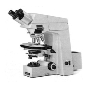
Zeiss JENA PLAN HD 9x12 User manual

-~
ARTISAN
®
~I
TECHNOLOGY
GROUP
Your definitive source
for
quality
pre-owned
equipment.
Artisan Technology
Group
Full-service,
independent
repair
center
with
experienced
engineers
and
technicians
on staff.
We
buy
your
excess,
underutilized,
and
idle
equipment
along
with
credit
for
buybacks
and
trade-ins
.
Custom
engineering
so
your
equipment
works
exactly as
you
specify.
•
Critical
and
expedited
services
•
Leasing
/
Rentals/
Demos
• In
stock/
Ready-to-ship
•
!TAR-certified
secure
asset
solutions
Expert
team
ITrust
guarantee
I
100%
satisfaction
All
tr
ademarks,
br
a
nd
names, a
nd
br
a
nd
s a
pp
earing here
in
are
th
e property of
th
e
ir
r
es
pecti
ve
ow
ner
s.
Find the Carl Zeiss Jena Plan at our website: Click HERE

Original text
Page 1
Contribute a better translation
Operation
instructions
JENA PLAN

Page 2
© Passing on and copying of this document, use or communication of
Contents is not permitted without express written authority. Violations
liable for damages. All rights created by patent grant or
Utility model registration.
This manual is not subject to change control.
Published by: Carl Zeiss Jena GmbH
Product range microscopes
Tatzendpromenade 1 a
O - 6900 Jena
Federal Republic of Germany
Number of
Instructions: B 0705-1
Publish date: 01/92
Digitized / reformatted: 07/2005Mi-VDD / Sandberg,

Page 3
B-0705-1 01/1992 (Digitized 07/2005) I
TABLE OF CONTENTS
1 DESCRIPTION Page
1.1 General, Information ............................................... .............................. 1-1
1.1.1 Name ................................................. ......................................... 1-1
1.1.2 Usage ................................................. .............................. 1-1
1.1.3 Module Overview ................................................. ............................ 1-1
1.1.3.1 Microscope equipment JENA PLAN ................................................ ......... 1-2
1.1.3.2 Additional equipment JENA PLAN ................................................ .............. 1-5
1.2 Specifications ................................................ .................................. 1-10
1.2.1 Dimensions and mass ............................................... ...................... 1-10
1.2.2 Environmental conditions ................................................. ............................. 1-10
1.2.2.1 Storage and transport (in packaging) ........................................... ... 1-10
1.2.2.2 Operating ................................................. .................................................. . 1-10
1.2.3 Operating Specifications ................................................ ...................... 1-10
1.2.4 Optical data ................................................ ...................................... 1-11
1.3 Description ................................................. ............................. 1-12
1.3.1 Mechanical Design ................................................ ............................ 1-12
1.3.2 Operation ................................................. ..................................... 1-14
1.3.2.1 General ................................................. ........................................... 1-14
1.3.2.2 Beam path ................................................. ......................................... 1-15
1.3.2.3 Function of the display, connection and control elements ....................... 1-16

Page 4
B-0705-1 01/1992 (Digitized 07/2005) II
2 OPERATION Page
2.1 Construction ................................................. .................................................. . 2-1
2.1.1 Unpacking ................................................. ............................................ 2-1
2.1.2 Setting up ................................................. .............................................. 2-3
2.1.3 Connecting ................................................. .......................................... 2-6
2.2 Operating ................................................. .................................................. . 2-7
2.2.1 Initial start ................................................. ............................... 2-7
2.2.2 Adjustments ................................................. ..................................... 2-7
2.2.2.1 Centering the lamp 12 V/100 W .......................................... ............. 2-7
2.2.2.2 Centering the cross table ............................................... ................... 2-9
2.2.2.3 Changing lenses and eyepieces ............................................. ....... 2-10
2.2.3 Illumination and contrast methods .............................................. ..... 2-11
2.2.3.1 Working with bright-field illumination (HF) ............................................ ....... 2-11
2.2.3.2 Working with dark-field illumination (DF) ............................................ .. 2-12
2.2.3.3 Working with oblique illumination .............................................. ........... 2-12
2.2.3.4 Working with polarization contrast ............................................... .......... 2-13
2.2.3.5 Working with differential interference contrast (DIK) ............................ 2-14
2.2.4 Measuring, counting and comparison method ........................................... .........2-15
2.2.4.1 Working with measuring plates ............................................... ........................ 2-15
2.2.4.2 Working with the monocular measuring tube P16x -10 ............................ 2-17
2.2.4.3 Working with the binocular measuring device ....................................... 2-17
2.2.4.4 Working with the electronic evaluation system RETARMET 2 ........ 2-18
2.2.4.5 Working with the Gefügevergleichsokular P10x .................................... 2-19
2.2.5 Photomicrograph ................................................. ...................................... 2-20
2.2.5.1 Large format camera ................................................. ................................ 2-23
2.2.5.2 Miniature camera ................................................. .................................... 2-23
2.2.5.3 Converting large format - small image .............................................. ........... 2-24
2.2.5.4 Universal device output ................................................ .................. 2-25
2.2.6 Other additional equipment ................................................ ................ 2-30
2.2.6.1 Demonstration use ................................................. ......................... 2-30
2.2.6.2 Slit diaphragms ................................................. ......................................... 2-31
2.2.6.3 Filter for epi-fluorescence excitation ............................................. .... 2-31
2.2.6.4 Cross table 20 x 20 mm ............................................. ............................. 2-32
2.2.6.5 Device microhardness testing mhp 100/45 -10 on .............................. 2-33
2.2.6.6 Lighting device 150 W Xe .............................................. ......... 2-34
2.2.6.7 Transmitted light CPR 6 V/25 W ........................................... ......... 2-34

Page 5
B-0705-1 01/1992 (Digitized 07/2005) III
3 Care, Maintenance, Service Page
3.1 Care ..................................................................................................... 3-1
3.2 Maintenance ................................................. ................................................. 3-2
3.2.1 Preventative maintenance ................................................ ........................... 3-2
3.2.2 Setting the Tubusbremse ............................................... ................... 3-2
3.2.3 Troubleshooting ................................................. ............................. 3-3
3.3 Service ................................................. .................................................. 3-4
ANNEX
- Manufacturer's certificate radio interference .............................................. A-1
- Abbreviations ................................................. ......................... A-2
- References ................................................. ............................... A-3
Page 6

B-0705-1 01/1992 (Digitized 07/2005) IV
IMAGE LIST
Figure 1-1 Microscope equipment JENA PLAN ................................................ ......... 1-2
Figure 1-2 Additional equipment JENA PLAN ................................................ .............. 1-5
Figure 1-3 Main assemblies JENA PLAN ................................................ ............... 1-12
Figure 1-4 Electric functional groups JENA PLAN ............................................ 1-14
Figure 1-5 Optical diagram JENA PLAN ................................................ ...................... 1-15
Figure 1-6 Functional elements JENA PLAN ................................................ ............. 1-21
Figure 2-1 Packaging JENA PLAN ................................................ ........ 2-1
Figure 2-2 Remove the dust caps ............................................... ......... 2-3
Figure 2-3 Loading the filter turret ............................................... ................. 2-3
Figure 2-4 Inserting the disk format ............................................... ..................... 2-3
Figure 2-5 Onset of binocular ............................................... ................. 2-4
Figure 2-6 Inserting the lenses ............................................... .......................... 2-4
Figure 2-7 Insertion of the cross table ............................................... .................... 2-4
Figure 2-8 Prepare the light ............................................... ............................. 2-5
Figure 2-9 Inserting / Replacing the Lamp ............................................. ............... 2-5
Figure 2-10 Installation and connection of control panels ......................................... 2-6
Figure 2-11 Connecting the mains voltage ............................................... .............. 2-6
Figure 2-12 Inserting the adjusting aid ............................................... ........................ 2-7
Figure 2-13 Preparing the lamp centering ............................................... ....... 2-8
Figure 2-14 Centering the lamp ............................................... ............................. 2-8
Figure 2-15 Centering the cross table ............................................... ................... 2-9
Figure 2-16 Changing lenses / eyepieces ............................................. .............. 2-10
Figure 2-17 Basic Settings ................................................. ............................... 2-11
Figure 2-18 Bright field illumination ................................................. .............................. 2-11
Figure 2-19 Inserting the slide DF .............................................. .................... 2-12
Figure 2-20 Working with oblique illumination .............................................. ........... 2-12
Figure 2-21 Insertion of the polarizer ............................................... ..................... 2-13
Figure 2-22 Inserting the analyzer ............................................... ...................... 2-13
Figure 2-23 Working with differential interference contrast (DIK) ............................ 2-14
Figure 2-24 Inserting the slide DIK .............................................. .................. 2-14
Figure 2-25 Inserting a Okularplatte ............................................... ................... 2-16
Figure 2-26 Attaching the measuring tube P16x -10 ............................................ ............. 2-17
Figure 2-27 Binocular measurement device ................................................ .................... 2-17
Figure 2-28 Prepare the binocular measuring device ............................................ 2-17
Figure 2-29 RETARMET 2 for length measurement .............................................. ......... 2-18
Page 7

B-0705-1 01/1992 (Digitized 07/2005) V
Figure 2-30 Gefügevergleichsokular P10x ................................................ ................ 2-19
Figure 2-31 Attaching the Gefügevergleichsokulars ............................................... . 2-19
Figure 2-32 Device setting photomicrograph ................................................ .......... 2-20
Figure 2-33 Control panel automatic exposure BA ............................................... ...... 2-21
Figure 2-34 Large format camera ................................................. ................................ 2-23
Figure 2-35 Miniature camera ................................................. .................................... 2-23
Figure 2-36 Converting large format ↔ Small image .............................................. ......... 2-24
Figure 2-37 Additional units for universal device output ................................ 2-25
Figure 2-38 Prepare the adjusting video ............................................. ............... 2-26
Figure 2-39 Dimension drawing ................................................. .............................................2-26
Figure 2-40 Prepare the T2 adaptation ............................................. .................... 2-27
Figure 2-41 Attaching the mf-AKS ............................................. ............................... 2-28
Figure 2-42 Connecting the mf-AKS ............................................. .......................... 2-28
Figure 2-43 Connecting the encoder mf-AKS DATEX ............................. 2-29
Figure 2-44 Attaching the demonstration use .............................................. 2-30
Figure 2-45 Working with slit diaphragms ............................................... ....................... 2-31
Figure 2-46 Inserting the fluorescence filter ............................................... ................ 2-31
Figure 2-47 Cross table 20 x 20 mm ............................................. ............................. 2-32
Figure 2-48 Components of the mhp 100/45 -10 aut ......................................... .................. 2-33
Figure 2-49 Attaching the mhp 100/45 -10 aut ......................................... ................ 2-33
Figure 2-50 Lighting device 150 W Xe .............................................. ......... 2-34
Figure 2-51 Preparation of the transmitted light equipment CPR 6 V/25 W ..............................2-34
Figure 3-1 Setting the Tubusbremse ............................................... ................... 3-2
NOTE
• The built-in text pictures wearing a frame number and a caption
for example, "2-8" means: In section 2, the image with the sequence number 8
The text discussed details are provided in the image with a reference stroke and local number (OZ).
In the current text "screw (2-8/3)" means the screw is in the image 8 of section 2
labeled with site number 3.
• Explanations of abbreviations are included in the appendix.
• This manual refers to the microscope equipment JENA PLAN HD 9x12
(See page 1-3) and their additional equipment.
When working with other unit types, please contact these instructions, mutatis mutandis.
Page 8

B-0705-1 01/1992 (Digitized 07/2005) VI
OVERALL VIEW
Page 9

B-0705-1 01/1992 (Digitized 07/2005) VII
PRODUCT LIABILITY
The incident-light microscope camera JENA PLAN including original accessories or additional equipment may
only be used for the microscopy method described in this manual.
For any other use, possibly also of individual modules or components may from
Manufacturers will not accept any liability. This also applies to all service or
Repairs that are not performed by authorized service personnel. Also
invalidates all Garantie-/Gewährleistungsansprüche also for the parts that are not directly
were affected by the repair.
The following warnings are of particular importance:
The microscope JENA PLAN was in accordance with IEC Publication 348-78,
Safety requirements for electronic measuring instruments, designed and tested and is in a
safe state has been delivered.
This manual contains information and warnings that the
Operator must be followed.
JENA PLAN is a latest scientific and technical knowledge
designed optical microscope for visual, micro photographic or video
Investigation of microscopic objects. The appliance is only for the intended
Use purpose. The device is not for unattended operation
determined!
The microscope has no particular protection against samples with
corrosive, toxic, radioactive or other adverse health effects.
The allowable sample weight (<5 kg) must not be exceeded.
It is to verify that the mains voltage at the back of the con-
corresponds to the value passed.
JENA PLAN is a device of protection class 1
The mains plug shall only be inserted in a socket outlet provided with a protective
Ground contact is provided. This protective measure is not a by using
Extension cord be rendered ineffective without a protective conductor. If the
The mains voltage by means of an auto-transformer, must not by this protective conductor
are interrupted. Any interruption of the protective conductor inside or outside the
Device or the removal of the protective earthing terminal brings danger to the
Device users and is therefore prohibited.
If the microscope is connected to the network, devices internal
Lead terminals dangerous voltages and the opening of covers or
the removal of parts (if it is not functional reasons) can possibly
expose hazardous live parts. The device is therefore disconnected from the mains,
before it is opened for adjustment, replacement, maintenance or repair.
If an adjustment, maintenance and repair of the under-voltage device
inevitably, this activity the which is to be performed by a qualified person in order
is aware of the hazard involved.
Existing openings should not be affected by covering their effect
be.
Page 10
This also applies to vent slots on the bottom. Ventilation slots and
an other openings must be no tools, objects and liquids in the
Device access.
B-0705-1 01/1992 (Digitized 07/2005) VIII
To cool down to room temperature For lamp replacement lamp can (cooling approximately15 min).
Vents and lamp housing have in operating temperatures and are
therefore not to touch. Was opened for lamp adjustment, the light, the
To avoid touching the lamp and lying in the vicinity parts strictly.
Make sure that only fuses of the required rated current and
the specified version will be used as a substitute. The use of
makeshift fuses and the short-circuiting of fuse holders are prohibited.
If it is possible that the protective measures are no longer effective, the device out must
Be taken down and secured against unintended operation.
The microscope is then assigned to the manufacturer or to a service with the
Send to workshop.
To avoid glare of the eyes is always a damping filter in the beam path to
leave. It is only to be removed from the beam path when the light intensity is too low
is.
When installing or removing cold, under high pressure xenon high pressure lamps in
and from the additional light Xe must shatter protection leather gloves with
Forearm tulips and a face shield may be used. The Xe lamp must after
Switching them off to cool to ambient temperature before they can be opened
(Cooling for at least 20 min).
It is on the proper disposal of used Xenon high pressure lamps
eighth!
It is forbidden to take the Xe lamp in the open state operation.
Device modifications due to technical
Progress are always reserved.
Page 11

B-0705-1 01/1992 (Digitized 07/2005) IX
Page 12
1 Description
1.1 General Information
1.1.1 Designation
Manufacturer description: epi-camera microscope reverse type

B-0705-1 01/1992 (Digitized 07/2005) 1 - 1
for routine JENA PLAN
Short name: JENA PLAN
Within the family of reflected light microscopes the JENA PLAN is classified as follows:
• upright type:
-JENATECH inspection
-JENAVERT
• reverse design:
-JENA PLAN
-JENAPHOT 2000
-NEOPHOT 32
1.1.2 Usage
The incident-light microscope camera JENA PLAN is a universal light microscope
reverse design with good image quality. In particular, it is suitable for visual,
micro photographic or video analysis of samples from the areas
Metallography, plastography, Ceramography and from the field of environmental protection.
ATTENTION The device must only for equipment described in this manual work and
Use cases are used. See also the Product Liability Statement
(S.VII).
1.1.3 Overview of Modules
The microscope is recommended in the following equipment:
• JENA PLAN with bright-field lenses and camera attachment 9 x 12 cm (H 9 x 12)
• JENA PLAN with HD lenses without built-in camera (HD)
• JENA PLAN with HD lenses and camera projection 24 x 36 mm (HD 24 x 36)
• JENA PLAN with HD lenses and camera attachment 9 x 12 cm (9 x 12 HD).
Page 13
1.1.3.1 microscope equipment JENA PLAN
4.2

B-0705-1 01/1992 (Digitized 07/2005) 1-2
Figure 1-1 microscope equipment JENA PLAN
Page 14

B-0705-1 01/1992 (Digitized 07/2005) 1-3
Page 15

B-0705-1 01/1992 (Digitized 07/2005) 1-4
•Part of the microscope equipment
NOTE For reasons of clarity, not all positions in Figure 1-1 are not illustrated.
Page 16
1.1.3.2

B-0705-1 01/1992 (Digitized 07/2005) 1-5
Page 17

B-0705-1 01/1992 (Digitized 07/2005) 1-6
Page 18

B-0705-1 01/1992 (Digitized 07/2005) 1-7
Page 19

B-0705-1 01/1992 (Digitized 07/2005) 1-8
Page 20
Table of contents
Other Zeiss Microscope manuals

Zeiss
Zeiss Smartzoom 5 User manual

Zeiss
Zeiss Lattice Lightsheet 7 User manual

Zeiss
Zeiss VivaTome User manual

Zeiss
Zeiss LSM 710 User manual

Zeiss
Zeiss Stemi 508 User manual

Zeiss
Zeiss LSM 880 User manual

Zeiss
Zeiss HBO 100 User manual

Zeiss
Zeiss Axioskop User manual

Zeiss
Zeiss LSM 800 User manual

Zeiss
Zeiss LSM800-6 User manual

Zeiss
Zeiss LSM 510 Inverted User manual

Zeiss
Zeiss Axioplan Universal microscope User manual

Zeiss
Zeiss Axiolab Pol User manual

Zeiss
Zeiss SV 6 User manual

Zeiss
Zeiss LSM 710 User manual

Zeiss
Zeiss Stemi 305 cam User manual

Zeiss
Zeiss Primo Star User manual

Zeiss
Zeiss S100/OPMI pico User manual

Zeiss
Zeiss Smartzoom 5 User manual

Zeiss
Zeiss Axioskop 2 FS plus User manual