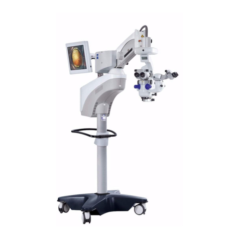
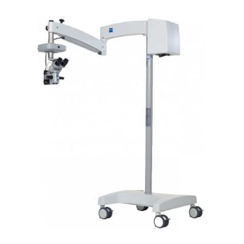
Zeiss OPMI 1 FC User manual

OPMI®
1
FC
Surgical
Microscope
]
Instructions
for
use
G
30-1003-e
]
1997-02-26

Regulations
and
standards
.
.
Notes
on installation
and
usage
.
Phototoxic
Retinal
Damage
in
Eye
Surgery
Warning
labels
and
notes
General
..
Safety
devices
OPMIS
1
FC
Surgical
Microscope
Binocular
tube
and
eyepieces
Installation
Attaching
the
microscope
Installing
the
binocular
tube,
the
eyepieces
and
the
09008
Connections
.
Re-equipping
the
microscope
Preparations
for
operation
Adjusting
the
balancing
system
Positioning
the
stand
E
Limitation
of
downward
movement
Friction
adjustments
Illumination
ㆍ
Adjusting
the
surgical
microscope

What
to
do
in
an
emergency
Maintenance,
further
information
................
24
Safe
working
order
..
24
Trouble-shooting
table
.
24
Exchanging
the
halogen
lamp
25
Care
of
the
microscope
26
Sterilization
.......
26
Magnifications
/
Fields
of
view
27
Moving
the
S21
Floor
Stand
28
Spare
parts
........
30
‘Accessories
30
Asepsis
..
30
Technical
data
に
oo
ev
uu
3
OPMIS
1
FC
Surgical
Microscope.
.
31
Important
for
safety
page
Satety
precautions
4
Satety
devices
10
‘Checklist.
n
21
What
to
do
in
an
emergency
22
Trouble-shooting
table
...
24
18301003
OPD!
FC
Suyca!
Morse
1097-0228

Safety
precautions
This
instrument
has
been
developed
and
tested
in
accordance
with
Carl
Zeiss
safety
standards
and
with
national
and
international
regulations.
A
high
degree
of
instrument
safety
is
thus
ensured.
It
is
recommended
in
these
regulations
that
the
manufacturer
explicitly
informs
the
user
about
the
safety
aspects
of
operating
the
instrument.
This
chapter
contains
a
summary
of
the
most
important
precautions
to
be
observed.
Further
safety
notes
are
also
contained
in
other
parts
of
this
user's
manual;
they
are
marked
with
a
warning
triangle
containing
an
exclamation
mark
as
shown
here.
Please
pay
special
attention
to
these
safety
notes.
Safety
is
only
ensured
when
this
instrument
is
op-
erated
properly.
Please
read
through
this
manual
carefully
before
turning
the
instrument
on.
Also
read
through
the
user's
manuals
of
the
other
equipment
used
with
this
instrument,
You
may
ob-
tain
further
information
from
our
service
organiza-
tion
or
authorized
representatives.
Regulations
and
standards
©
This
instrument
was
developed
in
accordance
with
the
following
regulations,
if
applicable:
-
ΕΝ
-
ЕС
-
UL
-
CSA
In
accordance
with
Directive
93/42/EEC,
Sup-
plement
Il,
Article
3,
the
quality
management
system
of
Carl
Zeiss
has
been
approved
by
TUV
Rheinland,
which
is a
notified
authority.
The
registration
number
is:
95 102
7601
ο
ο
ο
Nice
19974226
©
The
instrument
must
be
connected
to
an
‘emergency
backup
line
supply
in
accordance
with
the
regulations
or
guidelines
which
apply
in
your
country.
©
This
is
a
class
|
medical
instrument
as
defined
by
Directive
93/42/EEC.
*
The
declaration
on
CE
Conformity
contained
in
this
manual
is
only
valid
for
new
instruments
whose
delivery
package
includes
this
user's
manual.
This
declaration
is
invalid
for
old
in-
struments
which
do
not
feature
the
CE mark-
ing.
‧
Please
observe
alll
applicable
accident
preven-
tion
regulations.
Notes
on
installation
and
usage
General
©
Do
not
operate
the
equipment
contained
in
the
delivery
package
in:
-
explosion-risk
areas
—
the
presence
of
volatile
anesthetics
or
in-
flammable
solvents
such
as
alcohol,
benzin
or
similar
chemicals.
©
Do
not
station
or
use
this
instrument
in
damp
rooms.
Do
not
expose
the
instrument
to
water
splashes,
dripping
water
or
sprayed
water.
©
Immediately
unplug
any
equipment
that
gives
off
smoke,
sparks
or
strange
noises.
Do
not
use
the
equipment
until
our
service
represen-
tative
has
repaired
it.
©
Do
not
place
any
fluid-filed
containers
on
top
of
the
instrument.
Make
sure
that
no
fluids
can
seep
into
the
instrument.

ыы
ua
ta
l
l
l
ea
ως
了
|
ως
ha
tal
вы
ыы
μω
Do
not
force
cable
connections.
if
the
male
‘and
female
parts
do
not
readily
connect,
make
‘sure
that
they
are
appropriate
for
one
another.
K
any
of
the
connectors
are
damaged,
have
our
service
representative
repair
them.
If
desired,
the
unit
can
be
incorporated
into
po-
tential
equalization
measures.
Please
contact
our
service
representative.
Do
not
use
a
cellular
telephone
in
the
vicinity
of
the
equipment
because
the radio
interfer-
ence
can
cause
the
equipment
to
malfunction.
The
effects
of
radio
interference
on
medical
equipment
depend
on
a
number
of
various
fac-
tors
and
are
therefore
entirely
unforeseeable.
Modifications
and
repairs
on
this
instrument
and
on
instruments
used
with
this
instrument
may
only
be
performed
by
our
service
repre-
sentative
or
by
other
authorized
persons.
The
manufacturer
is
not
liable
for
damage
caused
by
unauthorized
persons
tampering
with
the
instrument;
such
tampering
will
also
forfeit
any
rights
to
claim
under
warranty.
Use
this
instrument
only
for
the
applications
described.
Only
use
this
instrument
with
the
accessories
contained
in
the
delivery
package.
Only
use
other
accessory
equipment
when
Carl
Zeiss
or
the
manufacturer
of
the
accessory
equipment
has
certified
that
its
usage
will
not
impair
the
safety
of
the
system.
Only
personnel
who
have
undergone
training
and
instruction
are
allowed
to
use
this
instru-
ment.
itis
the
responsibilty
of
the
customer
or
stitution
operating
the
equipment
to
train
and
instruct
all
staff
using
the
equipment.
Keep
the
user's
manuals
where
they
are
easily
accessible
at
all
times
for
the
persons
operat-
ing
the
instrument.
Never
look
at
the
sun
through
the
binocular
tube, the
objective,
or
an
eyepiece.
Do
not
pull
at
the
light
guide
cable,
at
the
pow-
er
cord
or at
other
cable
connections.
(3010096
OPS!
FO
Surg
Merca
1097.02.28
Safe
working
order
*
This
instrument
is
a
high-grade
technological
product.
In
order
to
ensure
optimum
perfor-
mance
and
safe
working
order
of
the
in-
strument,
we
recommend
that
our
service
re-
presentative
inspect
this
instrument
on
a
regu-
lar
basis.
If
a
failure
occurs
which
you
cannot
correct
us-
ing
the
trouble
shooting
table,
attach
a
sign
to
the
instrument
stating
it
is
out
of
order
and
‘contact our
service
representative.
Requirements
for
operation
Our
service
representative
will
install
the
instru-
ment.
Please
make
sure
that
the
following
require-
ments
for
operation
remain
fulfiled
in
the future:
=
All
mechanical
connections
(details
in
this
us-
er's
manual)
which
are
relevant
to
safety
are
properly
connected
and
screw
connections
tightened.
= All
cables
and
plugs
are
in
good
working
condition.
—
The
voltage
at
the
voltage
selector
on
the
sus-
pension
system
corresponds
with
the
rated
voltage
of
the
line
supply
on
site.
—
The
instrument
is
plugged
into
a
power
outlet
which
has
a
properly
connected
protective
earth
connection.
-
The power
cord
being
used
is
te
one
de-
signed
for
use
with
this
instrument.

|
Before
use
©
Make
sure
all
"Requirements
for
operation"
are
fulfilled.
©
Go
through
the
checklist.
©
Rerattach
or
close
any covers,
panels
or
caps
which
have been
opened
or
removed.
©
Pay
special
attention
to
warning
symbols
on
the
instrument
(triangular
warning
signs
with
‘exclamation
marks),
labels
and
any
parts
such
as
screws
or
surfaces
painted
red.
©
Do
not
cover
any
ventilation
grids or
siits.
During
use
+
The
long
extension
of
the
stand
base
must
al-
ways
point
in
the
direction
of
the
surgical
field.
©
|
Avoid
looking
directly
into
the
light
source,
e.g.
into
the
microscope
objective
or
into
a
fiber
light
guide.
©
if
a
light
guide
is
not
installed
in
one
of
the
light
guide
receptacies,
there
is
a
danger
of
fire
or
bum
injuries
when
the
illumination
is
on.
+
All
types
of
radiation
have
a
damaging
effect
on
biological
tissue.
This
also
applies
to
the
light
illuminating
the
surgical
field.
For
this
rea-
son,
reduce
the
brightness
and
the
duration
of
the
illumination
of
the
surgical
field
to
the
mini-
mum
required.
©
When
operating
on
the
eye,
always
use
pro-
tection
filter
GG
475
so
that
the
patient's
retina
is
not
exposed
to
unnecessary
(blue)
radiation.
(930400540
OMI
FC
Supa!
Meceeepe
19070228
After
use
Be
sure
to
turn
off
the
instrument
when
not
in
use.
Always
use
the
main power
switch
to
tum
it
off.
Re-equipping
the
microscope
Put the
suspension
arm
in
the top
position
be-
fore
changing
the
microscope
equipment
(mi-
croscope,
tube,
etc.).
When
finished,
the
bal-
ance
setting
of
the
suspension
system
must
be
re-adjusted.
The
weight
of
the
surgical
microscope
and
all
of
its
accessories
must
not
exceed
the
maxi-
mum
load
specified
for
the
suspension
system
being used.
Please
refer
to
the
user's
manual
of
your
suspension
system
for
the
maximum
load
allowed.
The
maximum
load
of
the
S21
Floor
Stand,
shown
in
figure
1, is
11
kg.

a
oe
A
O
a
ee
a
고
Phototoxic
Retinal
Damage
in
Eye
Sur-
gery
General
Several
papers
have
been
published
dealing
with
the
problems
of
phototoxicity during
eye
surgery.
A
comprehensive
review
of
these
publications
re-
veals
five
aspects
of
particular
concern:
—
Illumination
characteristics
(spectral
composi-
tion)
—
Intensity
of
illumination
=
Angle
of
illumination
=
Focus
of
the
light
source
=
Exposure
time
to
the
light
In
the
following,
comments
on
these
aspects
are
given
and
a
description
how
Carl
Zeiss,
as
a
man-
ufacturer,
makes
allowance
for
them
in
its
instru-
ments.
Illumination
characteristics
(spectral
composi-
tion)
Studies
on
exposure
of
the
eye
to
light
of
varying
spectral
composition
date
back
to
the
early
1950's.
These
studies
suggest
that
the
potential
hazard
of
phototoxic
damage
to
the
patient's
retina
can
be
reduced
by
blocking
out
the
blue
and
ultraviolet
light
below
a
wavelength
of
475
nm.
Carl
Zeiss
provides
a
GG
475
eye
protection
filter
for
surgical
microscopes
recommended
for
use
in
ophthalmic
surgery.
This
reduces
not
only
the
light
exposure
of
the
patient's
eye,
but
also
that
of
the
‘surgeon's.
(62010030
OPM?
FC
Sil
Morscapa
1997-0226,
|
It
should
be
noted
here
that
the
use
of
filters
will
of
necessity
cause
a
change
in
the
color
of
ilumina-
tion.
The
physician
may
need
to
become
familiar
with
the
resulting
changes
in
the
appearance
of
anatomical
structures.
Intensity
of
illumination
The
majority
of
researchers
suggest
that
the
sur-
geon
should
use
the
lowest
light
intensity
neces-
sary
to
guarantee
good
viewing
during
surgery.
Carl
Zeiss
has
addressed
this
concern
by
provid-
ing
a
device
for
continuously
varying
the
bright-
ness
of
the
light
source.
The
physician
is
thus
able
to
perfectly
adapt
the
light
intensity
at
the
patients
eye
to
the
conditions
existing
in
each
case. Zeiss
strongly
discourages
the
use
of
xenon
or
other
high-intensity
light
sources
in
ophthalmology.
Angle
of
illumination
A
number
of
publications
suggest
that
the
micro-
scope
should
be
tilted
to
reduce
the
exposure
of
the
macula
to
direct
illumination.
Carl
Zeiss
ophthalmic
surgical
microscopes
are
therefore
equipped
with
the
following:
=
Tilting
mechanism
for
microscope
body
=
Oblique
illumination
with
intensity
control

Focus
of
the
light
source
‘Studies
show
that
damages
are
likely
to
occur
if
the
filament
of
the
light
source
is
imaged
on
the
patient's
retina.
The
resulting
macular
edema
will
duplicate
the
pattern
of
the
illuminating
filament.
The
peak
intensity
of
the
filament
image
is
much
higher
than
the
peek
intensity
of
an
even
and
ex-
tended source
like
a
fiber
guide.
Carl
Zeiss
therefore
recommends
the
use
of
fiber
optic
illumination
for
axial,
coaxial
and oblique
illu-
mination.
This
provides
the
surgical
area
and
the
retina
with
even
and
diffuse
light.
Exposure
time
to
the
light
According
to
some
publications,
the
phakic
or
aphakic
eye
should
not
be
exposed
to
the
light
source
longer
than
a
few
minutes.
In all
surgical
cases,
the
retinal
exposure
time
depends
to
a
great
extent
on
the
surgical
technique,
the
effi-
ciency
of
the
surgeon
and
possible
case
complica-
tions.
It
is
therefore
recommended
in
ophthalmic
surgery
to
keep
the
light
intensity
as
low as
possi-
ble, or
to
use
a
device
which
prevents
light
from
entering
through
the
patient's
pupil.
Also,
the
sur-
rounding
light
sources
should
not
cause
additional
strain
to
the
eye.
Carl
Zeiss
has
provided
an
answer
to
this
problem
in
the
form
of
a
swing-in
retinal
protection
devi
for
insertion
into
the
beam
path
of
the
surgical
croscope.
This
device
ensures
total
eclipsing
of
the
pupil,
preventing
light
from
entering
through
it.
It
can
be
swung
out
when
a
red
reflex
is
required.
.09070090
opwe
FO
Surge
Moose
1997-0225,
In
conclusion
Carl
Zeiss
recommends:
—
Use
of
the
GG
475 eye
protection
filter
=
Reduction
of
the
illumination
of
the
surgical
ar-
ea
to
the
extent
required
for
the
patient’s
safe-
ty
and
for
microscopic
visualization
=
Tilting
of
the
microscope
body
as
required
—
Insertion
of
the
retinal
protection
device
—
Reduction
of
the
patient's
eye
to
light
expo-
sure from
surrounding
light
sources
These
measures
should
help
the
surgeon
to
re-
duce
the
likelihood
of
phototoxic
retinal
damage.
Warning
labels
and
notes
(figure
1)
Caution:
Observe
all
warning
labels
and
notes!
If
any
label
is
missing
on
your
instrument
or
has
become
illegible,
please
contact
us
or
our
autho-
rized
representative.
We
will
supply
the
missing
la-
bels.

Transportposition:
Moving
position:
Position
de
transport:
Posición
de
transporte:
max.
Belastung
max.
load
11
kg
see
instructions

General
The
OPMIS
1
FC
is
a
manually-operated,
multi-
purpose
surgical
microscope
designed
for
use
in
all
disciplines
as
a
=
surgical
microscope
=
examination
microscope
=
training
and
dissecting
microscope.
The
OPMI
1
FC
is
equipped
with
a
5-stage
mag-
nification
changer
which
is
operated
manually.
Fine-focussing
is
done
at
the
focus
knob
located
‘on
the
microscope
body.
The
focus
drive
has
range
of
50
mm.
To
change
the
viewing
angle,
you
can
tilt
the
mi-
croscope
in
stepless
motion.
The
friction
of
the
tit
motion
and
the
focussing
motion
can
be
adjusted
to
the
weight
of
the
microscope
equipment.
The
suspension
system
is
equipped
with
a
100
W
halogen
lamp.
The
light
is
conducted
to
the
micro-
scope
via
a
fiber
light
guide.
This
system
provides
for
coaxial
ilumination
of
the
field
of
view.
The
OPMIS
1FC
can
be
equipped
with
a
wide
range
of
accessories:
8“
or 0“
assistant's
microscope
-
|
various
coobservation
systems
-
photographic
and video
equipment
‘These
accessories
can
be
mounted
quickly
and
easily.
For
adjustment
of
the
depth
of
field,
we
recom-
mend
using
the
double
iris
diaphragm,
order
no.
3033
54.
0000.
ο
ο
ο...
This
user's
manual
describes
the
OPMI®
1
FC
to-
gether
with
other
units
and
accessories
(e.g.
the
821
Floor
Stand).
The
system
described
herein
re-
Presents
a
common
instrument
configuration
which
may
differ
from
your
system.
The
description
gen-
erally
applies
for
other
similar
configurations
2s
well.
Some
of
the
accessories
and
features
men-
tioned
may not
be
in
your
configuration:
The
scope
of
the
delivery
package
is
specified
in
the
delivery
papers.
Safety
devices
(figure
2)
1
Retinal
protection
fiter
GG
475
When
operating
on
the
eye,
always
use
pro-
tection
filter
GG
475
so
that
the
patient's
retina
is
not
exposed
to
unnecessary
(blue)
radiation.
Thermal
circuit
break
The
thermal
circuit
breaker
switches
off
the
halogen
lamp
in
the
lamp
module
when
it
over-
heats.
If
this
happens,
you
must
correct
the
cause
of
the
overheating.
For
example, drapes
might
be
covering
the
ventilation
slits.
Press
the
thermal
circuit
breaker
back
in
after
the
halogen lamps have
cooled
down.
Adjustment
screw
for
limitation
of
downward
м
The
safety
slider
is
used
to
limit
the
minimum
vertical
working
distance
to
the
field
of
sur-
gery.
This
setting
must
be
adjusted
before
sur-
gery.

nn
-
ео
11
4
ntial
egualization
connection
6
Lock
knobs
This
connection
can
be
used
to
incorporate
Press
these
knobs
in
to
lock
the
stand
in its
the
unit
in
potential
equalization
measures.
position
on
the
floor.
To
release
the
knobs,
s
papes
press
in
the
toe-plates
located
underneath.
Back-up
lamp
module
If
one
of
the
fiber
illuminations
fail,
pull
out the
7
Lock
screws
defective
lamp
module
and
insert
the
back-up
In
addition
to
lock
knobs
(6),
tighten
these
lamp
module.
Exchanging
the
halogen
lamp
is
screws
to
lock
the
stand in
its
position
on
the
described
on
page
25.
floor.
99010020
ΟΡΜΟΊ
ΠΟ
Sunjel
Meroscop
197.0028,

OPMI®
1
FC
Surgical
Microscope
(figure
3)
1
Securing
screw
This
securing
screw
retains
the
microscope
in
the
reception
bore
of
the
stand and
secures
it
from
falling
out.
Be
sure
to
screw
in
this
screw
firmly
(using
a
suitable
tool)
as
far
as
it
will
go.
2
Rotation
shaft
Before
inserting
the
rotation
shaft
of
the
micro-
scope
into
the
reception
bore
of
the
suspen-
sion
system
or
the
tilt
coupling,
lubricate
the
shaft
lightly
with
grease
F30
(cat
no.
0092
214).
Light
quide
clip
Securing
screw
After
installing
the
binocular
tube
or
another
unitin
the
receptacle
of
the
microscope,
tight-
en
this
screw
firmly
as
far
as
it
will
go.
5
Cover
cap
You
can
remove
this
cap
and
install
a
handle
for
guiding
the
microscope.
6
Friction
adjustment
knob
for
tilt
motion
The
tit
position
of
the
microscope
can
be ad-
justed
around
the
tilt
axis.
Use
this
knob
to
ad-
just
the
friction
of
the
tilt
motion.
Turn
the
knob
clockwise
to
tighten
the
friction
and
counter-
clockwise
to
loosen
the
friction.
Gsor00se
OPS!
FO
Sua!
Merscope
19970226
10
1
12
13
Focusing
knobs
(located
on
both
sides)
Adjust
the
friction
of
the
focusing
drive
by
tum-
ing
the
two
knobs
in
opposite
directions.
S-stage
magnification
changer
Five different
magnifications
can
be
selected.
The
number
indicated
at
the
black
line
shows
magnification
factor
y
of
the
magnification
changer:
¥=0.4;
y=0.6;
y=
1.0;
y=
1.6
y=2.5x.
You
can
calculate
the
magnification
of
the
en-
tire
system
and
the
diameter
of
the
field
of
view
as
described
on
page
27.
Potential
equalization
connection
This
connection
can
be
used
to
incorporate
the
unit
in
potential
equalization
measures.
Light
quide
receptacle
Dust
cover
Remove
this
cover
before
installing
the
binocu-
lar
tube
or
a
different
unit.
Cover
cap
for
filter
slider
A
filter
slider
can
be
installed
here
after
remov-
ing
the
cap.
Screwholes
for
attaching
dovetail
mount
A
dovetail
mount
(cat.
no.
30
33
60-
9903)
for
accessory
equipment
can
be
installed
on
the
bottom
of
the
microscope.


Binocular
tube and
eyepieces
(igure
4)
1
Catch
lever
for
diopter
adjustment
The
eyepieces
are
equipped
with
ametropia
compensation
between
-8
to
+8
D.
To
adjust
the
eyepiece,
press
in
the
catch
lever
and
turn
the
eyepiece
in
the
+
or
-
direction.
The
set-
ting
cannot
be
inadvertently
changed
after
the
catch
lever
has
snapped
back
in.
2
PD
adjustment
knob
Adjust
the
interpupillary
distance
with
this
knob.
When
adjusted
correctly,
the
image
is
sible
as
one
image
through
both
eyepieces.
3
Screw
ring
When
attaching
the
eyepieces,
tighten
this ring
firmly.
4
Diopter
scale
The
refractive
power
is
shown
on
the
diopter
scale.
5
Eyecup
When
adjusting
the
eyepieces,
set
the
eyecups
so
that
the
entire
field
of
view
can
be
seen.
(901005
OPM1
FO
Supa
Moscone
1607-0228
14

Installation
Note:
The
principle
described
in
this
chapter
also
applies
for
al
other
suspension
systems.
Attaching
the
microscope
(figure
5)
15
Caution:
The
weight
of
the
microscope
and
all
the ac-
cessories
must
not
exceed
maximum
11
kg
when
using
the
$21
Floor
Stand.
+
Tum
the
balance
adjustment
screw
(1)
clock-
wise
until
the
weight
compensation
scale
reads
11
kg.
When
doing
this,
move
the
sus-
pension
arm
a
bit
up
or
down
to
the
position
where
screw
(1)
turns
easily.
©
Loosen
securing
screws
(3)
and
(6)
a
few
tums.
‧
Lubricate
the
microscope
rotation
shaft
(4)
with
grease
F30
(cat.
no.
0093
214).
+
insert
the
microscope
rotation
shaft
(4)
into
the
reception
bore
of
the
suspension
arm.
Tighten
securing
screw
(2)
using
a
suitable
tool
(e.g.
a
pin
key).
Tighten
securing
screw
(3)
firmly.
The
secur-
ing
screw
(8)
must
engage
groove
(6).
This
is
ensured
when
securing
screw
(3)
is
flush
with
the
surface
of
the
suspension
arm.
(9010094
OPM!
FO
Sunjel
Meroscope
1007.0220
Caution:
Before
using
the
instrument
and
after
re-
equipping
it,
always
ensure
that
securing
‘screws
(2)
and
(8)
are
tightened
firmly!

Installing
the
binocular
tube,
the
eye-
pieces
and
the
objective
(figure
6)
*
Loosen
securing
screw
(5)
a
few
turns.
*
Remove
cover
(1)
and
store
it.
©
Place
binocular
tube
(4)
onto
the
surgical
croscope
and
tighten
securing
screw
(6)
firmly.
Note:
Other
components
may
be
installed
between
the
microscope
and
the
tube.
These
components
are
secured
in
the
same
manner
using
securing
screw
(6).
©
Screw
the
eyepieces
(2)
onto
the
eyepiece
mounts
and
tighten
knurled
rings
(3)
firmly.
16
Note:
If
a
documentation
device
is
used,
an
eyepiece
with
a
reticle
can
be
used
as
a
focusing
aid.
In-
stallation
of
the
reticles
can
only be
done
in
the
factory
or
by
our
service
representative.
Always
use
the
eyepiece
equipped
with
the
reticle
on
the
‘same
side
of
the
binocular tube
as
the
documenta-
tion
equipment
is
installed.
‧
Screw
the
objective
(6)
into
the
microscope
body
and
tighten
firmly.
Caution:
Before
using
the
instrument
and
after
re-
equipping
it,
always
make
sure
the
following
are
securely
mounted:
=
_
binocular
tube
(4)
Make
sure
the
following
are
tightened
firmly:
-
knurled
rings
(3)
securing
screw
(5)
objective
(6)
(880-100
mat
FO
Surge
Meroscoge
19970226
TA
AAN
AO
SO
O
PR
js
PR
PO
pe
p
mn

Connections
(figures
7,
8
and
9)
©
Check
the
voltage
setting
at
(3).
Notes:
-
The
instrument
is
set
at
the
factory for
the
voltage
of
the
destination
country.
The
setting
indicated
by
(3)
must
be
the
same
as
the
avail-
able
line
voltage.
If
not,
our
service
technician
will
have
to
re-wire
the
instrument.
-
Tum
the
unit
off
at
the
power
switch
(2)
before
plugging
in or
unplugging
the
power
cord.
*
|
Plug
the
power
cord
(4)
into
a
wall
outlet.
Only
plug
the
power
cord into
a
power
outlet
which
is
equipped
with
a
properly
connected
ground
contact.
+
Insert
the
light
gui
of
the
microscope
and
into
light
guide
recepta-
cles
(1)
and
(5),
and
then
press
the
light
guide
into
clips
(6).
There
must
be
enough
slack
in
the
light
guide
so
that
it
is
not
stretched
when
the
microscope
is
tilted
or
rotated.
17
(3010094
OPA!
FC
Suns!
Morocco
1987-0028,

Re-equipping
the
microscope
(figures
10
and
11)
©
Turn
the
balance
adjustment
screw
(1)
clock-
wise
until
the
weight
compensation
scale
reads
11
kg.
When
doing
this,
move
the
sus-
pension arm
a
bit
up
or
down
to
the
position
where
screw
(1)
turns
easily.
10
18
Remove
the
microscope
accessories
in
re-
verse
order
as
described
on
pages
16
to
17.
Re-equip
the
microscope
as
described
on
pages
15
to
17.
Caution:
Hold
on
to
the
microscope
tightly
when
loosen-
ing
securing
screws
(3)
and
(7).
83016088
OPMET
FO
Sugcel
Momscope
10070226
ns

Preparations
for
operation
Adjusting
the
balancing
system
(figures
10
and
11)
*
Lift the
microscope
a
bit
with
your
hand
until
you
find
a
position
where
the
balance
adjust-
‘ment
screw
(1)
can
be
easily
tumed.
‧
Adjust
balance
adjustment
screw
(1)
to
where
the
microscope
no
longer
moves
up
or
down
when
you
let
it
loose.
‧
Check
the
balance
adjustment
in
various
posi-
tions
and
finely
adjust.
When
properly
bal-
anced,
the
microscope
should
remain
in
any
position
it
is
put
into.
The
effort
required
to
move
it
up
and
down
should
be
the
same.
Positioning
the
stand
See
also
"moving
the stand”,
page
28.
Caution:
The
long
extension
of
the
stand
base must
al-
ways
point
in
the
direction
of
the
surgical
field.
©
Press
down
the
floor
lock
knobs
(pos.
8,
page
29)
so
that
the
stand
cannot
be
rolled
away.
*
Screw
in
the
lock
screws
(pos.
9,
page
29).
11
9
№
(04040080
OP!
FC
Sul
More
10970226
19
Limitation
of
downward
movement
The
downward
movement
of
the
suspension
arm
can
be
limited
so
that
the
microscope
cannot
be
accidentally
lowered
to
where
there
is
a
risk
to
the
patient.
©
Adjust
knob
(2)
so
that
the
microscope
cannot
be
lowered
beyond
a
minimum
safety
distance
to
the
patient.
Check
the
stop
setting by
lowering
the
surgical
microscope
to
the
stop.
Friction
adjustments
©
Adjust
the
friction
of
the
horizontal
movement
‘of
the
suspension
system
and
the
rotation
of
the
microscope
using
knobs
(4)
and
(10).
©
Adjust
the
friction
of
the
tilt
motion
at
knob
(5).
Tighten
the
friction
by
turning
clockwise.
*
Tum
the
focusing
knobs
(8)
in
opposite
direc-
tions
to
adjust
the
friction
of
the
focus
drive.
©
Adjust
the
friction
of
vertical
movement
at
knob
(9).
Wumination
©
Switch
on
and
adjust
the
brightness
at
knob
(6).

Adjusting
the
surgical
microscope
20
Bring
the
surgical
microscope
into
starting
position
within
the
focusing
range.
Set the
minimum
magnification
on
the
surgical
microscope.
Bring
the
surgical
microscope
into
working
position.
‘Adjust
interpupillary
distance
on
the
binocular
tube.
Set
diopter
scales
on
eyepieces.
Note
that
instrument
myopia
may
occur.
у
у
Emmetropes
set the
diopter
scale
to
Ametropes
(who
do
not
know
their
refractive
powers)
0
diopter
(D)
у
Eyeglass
wearers
(who
perform surgery
wearing
Set
both
eyepieces
to
+8
D.
their
glasses)
set
the
diopter
scale
to
0
diopter
(D)
у
у
Ametropes
(who
know
their
refractive
Eyepieces
without
reticles:
Eyepieces
with
reticles:
powers
and
perform
surgery
у у
without
wearing
their
glasses)
set
the
diopter
scale
ring
to
their
refractive
powers.
Remove
binocular
tube
and
eye-
pieces
from
the
microscope
body
and
point
them
at
a
distant
ob-
ject’,
Le.
use
them
like
a
pair
of
binoculars.
The
image
of
the
ob-
jectis
sillunsharp
Tum
diopter
scale
ring
on
eye-
piece
slowly
clockwise
until
the
reticle
is
imaged
sharply.
Stop
turning
the
ring,
у
y
Tum
diopter
scale
ring
of
one
eye-
piece
slowly
clockwise
until
the
image
of
the
object
is
sharp.
Stop
tuming
the
ring.
И
necessary,
re-
eat
this
procedure
three
times
and
take
the
average
of
the
read-
ings
found.
Adjust
the
second
eye-
piece
in
the
same
manner.
Focus
the
surgical
microscope
on
the
object.
The
reticle
and
the
ob-
ject
must
be
sharp
at
the
same
time.
у
у
Replace
tube
and
eyepieces
on
microscope
body
and
tighten
se-
‘curing
screw
firmly.
‘Adjust
the
second
eyepiece
in
the
same
manner
until
the
object
is
у
seen
sharply.
field
changes.
‘Adjust
eyecups
in
such
a
way
that
the
ful
field
ol
view
can
be
seen.
Set
maximum
magnification
on
the
microscope
and
focus
on
object.
Set
working
magnification
required.
When
the
magnification
is
changed,
the
focal
plane
is
retained,
but
the
depth
of
Note:
If
several
surgeons
use
the
instrument,
itis
advisable
to
draw
up
a
table
with
the
individual
refractive
powers
of
‘each
of
the
surgeons
and
to
keep
it
in
a
handy
location
near
the
instrument.
7
||
Caution:
Never
point
at
the
sun.
ee
Table of contents
Other Zeiss Microscope manuals

Zeiss
Zeiss OPMI CS User manual

Zeiss
Zeiss Axiocam 105 color User manual

Zeiss
Zeiss EXTARO 300 User manual

Zeiss
Zeiss Primo Star User manual

Zeiss
Zeiss Axiovert 200 User manual

Zeiss
Zeiss Stemi 305 User manual

Zeiss
Zeiss opmi lumera 700 Installation guide

Zeiss
Zeiss VISU 200 User manual

Zeiss
Zeiss Axiolab 5 User manual

Zeiss
Zeiss OPMI 1 FR pro Instruction manual

Zeiss
Zeiss Primovert User manual

Zeiss
Zeiss Smartzoom 5 User manual

Zeiss
Zeiss Axioskop User manual
Zeiss
Zeiss LSM 700 User manual

Zeiss
Zeiss JENA PLAN HD 9x12 User manual

Zeiss
Zeiss AxioExaminer FTP-2100 User manual

Zeiss
Zeiss JENAVAL User manual

Zeiss
Zeiss Axiostar plus User manual

Zeiss
Zeiss Axiolab 5 User manual

Zeiss
Zeiss Axio Scope.A1 User manual